Body component maintenance and replacement
Precautions of electric technician who use Medical Electronic Equipment
Inspection of key points before the maintenance
Precautions of auxiliary restraint system "airbag" and "seat belt pretension"
Precautions of removing the 12V battery
Body component maintenance and replacement
Safety Precaution
Precautions of electric technician who use Medical Electronic Equipment
Warning:
● Strong magnetic components have been assembled on this vehicle.
● Technicians shouldn't operate electronic pacemaker or other medical electronic devices in this vehicle, or the functions of medical devices may be affected by strong magnetic components.
Precautions for normal charging
Warning:
●
If a technician uses a medical electric device
such as an implantable cardiac pacemaker or a
heart pacemaker/defibrillator, the effects of the devices must be checked
before starting the charge operation.
●
If a technician using a medical electric device
such as implantable cardiac
pacemaker or an implantable heart pacemaker defibrillator .he must not enter
the vehicle compartment (including luggage room) during normal charge
operation.
Communication equipment operation precautions
● If the technician uses medical electronic devices such as cardiac pacemaker, cardioverter or defibrillator and other medical electronic equipment, please keep enough distance with the communication devices.
● The electromagnetic wave of the remote intelligent terminal may affect the function of the medical device such as cardiac pacemaker, cardioverter, defibrillator and other medical electronic devices.
● If the technician uses the medical device such as cardiac pacemaker, multiplexer, defibrillator and other medical electronic equipment, the electromagnetic wave of the remote intelligent terminal may affect the function of the device. The possible effect of the remote intelligent terminal on the medical electronic devices must be checked by the manufactures of the medical electronic devices .
Inspection of key points before the maintenance
The high-voltage system may automatically operate. Please confirm the remote air conditioning and fixed-time charging haven’t been set before the maintenance.
Attention:
If remote air-conditioning or fixed-time charging is set, the high voltage system will run automatically even the switch is off.
Precautions of auxiliary restraint system "airbag" and "seat belt pretension"
The
Supplemental Restraint System such as “AIR BAG” and “SEAT BELT PRE-TENSIONER”,
used along
with a front seat belt, helps to reduce the risk or severity of injury to the
driver and front passenger for certain types of collision. This system includes
seat belt switch inputs and dual front air bags. Information necessary to
service the system safely is included in the “SRS AIR BAG” and “SEAT BELT” of
this Service Manual.
Warning:
Always observe the following items for preventing accidental activation:
● To avoid rendering the SRS inoperative, which could increase the risk of personal injury or death in the event of a collision that would result in air bag inflation, all maintenance must be performed by an authorized JAC dealer.
●
Improper maintenance, including incorrect
removal and installation of the SRS, can lead to personal
injury caused by unintentional activation of the system. For removal of Spiral
Cable and Air Bag Module, see “SRS AIR BAG”.
● Do not use any electrical test devices to test any circuit of the auxiliary restraint system unless these tests are in the instructions described in the service manual. The wire harness and connectors of the auxiliary restraint system should adopt to yellow or orange color.
Precautions when using power tools(pneumatic or electric) and hammer
●
When working near the Air Bag Diagnosis Sensor Unit or other Air
Bag System sensors with the power switch ON, never use air or electric power
tools or strike near the sensor(s) with a hammer. Heavy vibration could
activate the sensor(s) and deploy the air bag(s), possibly causing serious
injury.
● When using power tools or a hammer, turn the key in the "LOCK" position, unplug the cathode of 12V lead-acid battery and wait at least 1 minute for maintenance.
Precautions of removing the 12V battery
When removing the 12V battery, turn the power switch to “ON”, and then to “OFF”.
Note:
● The automatic 12V battery charge function may start even when the power switch is in “LOCK”state.
● The automatic 12V battery charge control does not start within approximately one hour when the power switch is turned ON/OFF.
● Before the repairing which no need the power: rotate the key to LOCK gear and disconnect the 12V battery negative.
● After disconnect the 12V battery negative, the memory of radio and other control devices will be cleared.
● Replace new oil seal, gasket,gasket ring,O-type ring,lock washer,cotter pins,self-locking nuts and other parts.
● Place the removed parts in order and according to the positions as they are assembled .
● If necessary, use approved binders, sealants or equivalent products.
● For safe and efficient repair work, you should use hand tools, power tools (disassembly only) and special tools.
● Before repairing the vehicle:
Cover the fender, interior and carpet with a suitable cover. Be careful do not scratch the paintwork with keys, buttons or something like this.
Body component maintenance and replacement
Overview
● This section is used to provide guidance to the technicians with higher skills and experience in the maintenance of collision vehicles, and will use the modern service tools and equipment Those who do not have the vehicle body repair skills do not attempt to use the methods in this section to repair the vehicle.
● Encourage technicians to read the body repair manual (basic version) to guarantee the original function and quality of the vehicle The body repair manual (basic version) contains additional information, caution and warning that are not included in this manual. The technician shall refer to the two operating manuals to confirm the proper maintenance methods.
● Please note that this manual is a worldwide version, and there may be some procedures that are not applicable to some countries and regions.
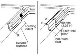
The front pillar connection points can be anywhere in the shaded part of the picture. According to the structure of the body, the optimum connection point is A.
Confirm the shearing position and record the distance from the locking mark. According to the distance records to shear the repair parts. Cut out the outer panel of front pillar at the 60mm upper the inner panel of front pillar .
In order to facilitate the shearing of front pillar outer panel, please prepare shear fixture. At the same time, it will also make maintenance parts can be accurately shear in the junction.
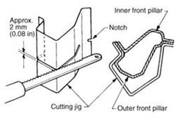
Examples of searing operations with fixture are as follows.
1. Mark shear line A: shear position of front pillar outer plate B: shear position of front column inner plate;
2.Align the shear line and notch of the fixture to clamp the front column;
3.Cut the front pillar outer plate(A position) along the groove of the fixture.
4.Remove the fixture and cut out the rest part.
5.Cut the front pillar inner plate(B position) with the same method.

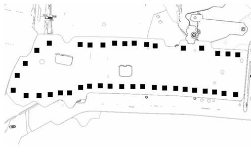
Replacement of outboard longitudinal beam (right and left symmetrically)
The solder joint as below:


Replacement of outboard longitudinal beam (right and left symmetrically)
The solder joint as below:
![]()
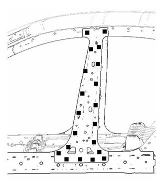
Replacement of outer panel of rear wall
The solder joint as below:


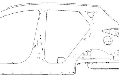
Replacement of the rear part of the side wall outer panel(right and left symmetry)
The solder joint as below:


![]()
Replacement of the threshold part of the side wall outer panel(right and left symmetry)
The solder joint as below:


Replacement of the B pillar of side wall(right and left symmetry)
The solder joint as below:
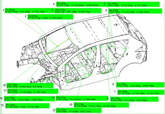
Vehicle body size check
Vehicle body data
In the body maintenance process, in order to guarantee the running performance of the car and the better service for you, the repair personnel should check the size of body-in-white accordance to the following size.
|
Data measured points |
Position information |
Numerical value(mm) |
|
1 |
The distance from the middle of the top cover to the middle of the upper outer plate of the ventilated cover plate. |
764 |
|
2 |
The distance from the middle of the top cover to the bottom dead center of front windshield. |
829 |
|
3 |
The distance from the A pillar to B pillar at R angle above the bottom dead center of front door frame. |
1007.8 |
|
4 |
The length of the he bottom dead center of B pillar front door frame |
883.5 |
|
5 |
The distance from the B pillar to V pillar at R angle above the bottom dead center of rear door frame. |
813.5 |
|
6 |
The oblique diagonal length from front top to rear bottom of the rear door frame. |
949.3 |
|
7 |
The height of rear door frame |
960.2 |
|
8 |
The oblique diagonal length from front bottom to rear top of the rear door frame. |
974.5 |
|
9 |
The width of the bottom dead center of rear door threshold |
336.4 |
|
10 |
Front door frame height |
952.1 |
|
11 |
The oblique diagonal length from front top to rear bottom of the front door frame. |
945.5 |
|
12 |
The width of the bottom dead center of front door threshold |
728.3 |
|
13 |
The length of the he bottom dead center of A pillar front door frame |
630 |
|
14 |
The oblique diagonal length from front top to rear bottom of the front door frame. |
1316.8 |
|
15 |
Distance from the middle of the upper outer plate of the ventilated cover to the upper end of the front windshield |
806.4 |
|
16 |
The gap distance of R angle below the windshield’s bottom dead center of the right and left side wall outer panel. |
1344.3 |
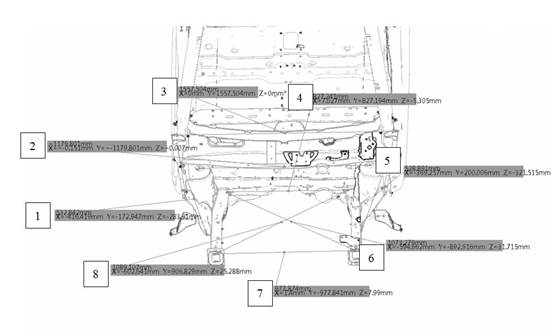
Engine bay data
In the body maintenance process, in order to guarantee the running performance of the car and the better service for you, the repair personnel should check the size of body-in-white accordance to the following size.
|
Data measured points |
Position information |
Numerical value(mm) |
|
1 |
The length of right front suspension side beam |
532.8 |
|
2 |
The hole center gap of left and right front shock absorber mounting plate |
1179.8 |
|
3 |
The maximum width of the connection position of left and right side wall with engine bay |
1557.5 |
|
4 |
The maximum length of overlap of the front crossbeam and engine bay |
827.2 |
|
5 |
The length of left front suspension side beam |
528.9 |
|
6 |
The distance from the front end of left engine bay front stringer to the diagonal front wall crossbeam |
1073.3 |
|
7 |
The hole center gap of the front panel of the left and right engine bay front stringer |
977.9 |
|
8 |
The distance from the front end of right engine bay front stringer to the diagonal front wall crossbeam |
1089.1 |
Beam data
In the body maintenance process, in order to guarantee the running performance of the car and the better service for you, the repair personnel should check the size of body-in-white accordance to the following size.

|
Data measured points |
Position information |
Numerical value(mm) |
|
1 |
The inner wall gap of the left and right stringer of rear floor |
914.0 |
|
2 |
The hole gap of left and right mounting plate at the side rear of the battery |
984.3 |
|
3 |
The gap of the left and right mounting holes of the rear suspension |
1130.0 |
|
4 |
The rear part inner wall gap of the left and right stringer behind the floor |
1061.7 |
|
5 |
The hole gap of the rear part of the engine bay left and right stringer |
895.0 |
|
6 |
Interval of right front assembling holder holes and secondary frame |
922.0 |