Precautions for normal charging
High-voltage preventive measure
High-voltage cable and safety sign
Handling of high voltage terminals
Regulation for a person wearing medical electronic device
Forbidden accompanying article during work
Place “Repairing High-voltage Parts, No Touch!” warning sign 3
Precaution for removing 12V battery
Precaution for supplemental restraint system "airbag" and "safety belt pretension"
Malfunction of rear window defrosting
Malfunction of outside rearview mirror glass
Safety precaution
Precautions for normal charging
Warning:
● If an engineer uses medical electronic devices including heart pacemaker, cardioverter, defibrillator, the device can be only be used after its function being checked and confirmed before charging.
● During normal charge operation, an engineer who uses medical electronic devices including heart pacemaker, cardioverter, defibrillator cannot enter passenger compartment (including trunk).
High-voltage preventive measure
Warning:
● The electric vehicle has a high-voltage battery. If the operation on the vehicle and high-voltage parts is incorrect, there are risks of leakage of electricity, electric shock, or similar accidents. Thus, it is mandatory to follow correct procedures to check and maintain.
● Before disconnecting repair switch, please put the key on “LOCK” position or unplug the key.
● Disconnect repair switch before checking or maintaining high-voltage system. It is forbidden to close repair switch during the process of checking and maintenance. Before starting the operation on high-voltage system, be sure to wear insulated protection equipment, including gloves, shoes, and glasses.
● When a technician is operating high-voltage system, please ensure no one touching the vehicle. When there is no maintenance operation, please take insulated protection on the high-voltage sections to prevent anyone touching.
● When repair switch disconnects, it is forbidden that the key is at “ON” position or switched to “START” position.
High-voltage cable and safety sign
The color of high-voltage cable is orange and there are safety signs on the power battery assembly and other high-voltage parts. Do not touch these cables and parts.
Handling of high voltage terminals
When the connector of high-voltage cable is plugged out, please use insulated adhesive tape to bind up immediately.
Regulation for a person wearing medical electronic device
The vehicle has strong magnetic parts. If an engineer uses medical electronic device, such as electronic pacemaker, its function may be affected by strong magnetic parts. Thus, these people cannot carry out repair work.
Forbidden accompanying article during work
The vehicle has strong magnetic parts. Thus, during work it is forbidden to take metal articles which may cause short circuit or magnetic articles such us various bank cards which may be damaged.
Place “Repairing High-voltage Parts, No Touch!” warning sign
Before repairing high-voltage parts, please place “Repairing High-voltage Parts, No Touch” warning sign on the prominent position of the repaired vehicle to remind other people.
Precaution for removing 12V battery
Before removing 12V battery, turn the key to “ON” position, and then turn to “LOCK” position
Reminder:
● Though the key is at “LOCK” position, auto-recharge function of 12V battery may activate.
● After the key turns from “ON” to “LOCK”, auto-recharge function of 12V battery will not activate.
Precaution for supplemental restraint system "airbag" and "safety belt pretension"
Supplemental restraint system “airbag” and “safety belt pretension” is used together with front seat safety belts, which can reduce the damage to the driver and front passenger during collision. Supplemental restraint system consists of safety belt, driver airbag, and front passenger airbag. The detailed information of supplemental restraint system is included in the chapters of airbag system and seat safety belt.
Warning:
In order to avoid accidents, please abide by the following content:
● To avoid the failure of supplemental restraint system and considering that the risk of physical injuries will increase during collision if the system fails, all the service must be executed by JAC authorized dealer.
● Non-normative maintenance of supplemental restraint system including non-normative removal and installation may result in accidental trigger of the system and cause physical injuries. Regarding the method of removing airbag module, please refer to Airbag System chapter.
● Except for the operations in the service manual, please do not use electrical test device to test any circuit of supplemental restraint system. The color of harness and connector of supplemental restraint system is yellow or orange
Precaution for using power tool (pneumatic or electric) and hammer
● When power switch is at “ON” position and approach airbag diagnosis sensor or other sensors of airbag system, please do not use power tools or hammer on the sensor part area. Violent vibration may trigger these sensors and airbag to cause serious injuries.
● When using power tools or hammer, put the key at “LOCK” position, unplug the negative pole of 12V lead-acid battery, wait at least one minute, and then start maintenance.
Preparation work
Lubricant and coolant
|
Name |
Usage |
Remark |
|
Refrigerant R-134a |
Refrigeration cycle |
|
|
Compressor lubricant RL68H |
Compressor lubricant |
|
Special tool
|
Name Tool |
Picture |
Tool Name |
Picture |
|
Digital multimeter |
|
High strength invisible light |
|
|
Removal pincher |
|
Triple table |
|
|
Halogen leakage detector |
|
Color tracer syringe |
|
|
Dye tracer R134a |
|
Microthermometer |
|
|
Positive flow controlling valve |
|
Axle sealing protection equipment |
|
|
Refillable recycling tank of 50pounds |
|
Pressure test adapter |
|
|
Lip shape seal removal tool for air conditioning system |
|
O- ring seal removal tool |
|
|
Valve core removal and installation tool |
|
O-ring seal installation tool |
|
|
Spring card plier |
|
Spring card plier |
|
|
Refrigerant recycling, regeneration, filling system |
|
Passive testing amp |
|
|
Heating gun |
|
Insulated gloves |
|
|
Insulated shoes |
|
Aspirator bump |
|


|
Serial number |
Component name |
Function |
|
1 |
BCM |
Receive defrosting instruction, control defrosting relay in the low voltage terminal box, and execute defrosting timing control. |
|
2 |
Touch panel(including rear defrosting button)
|
Send defrosting instruction to air conditioner controller through CAN communication, and then the indicator light is on. |
|
3 |
Outside rearview mirror glass heater |
To heat the glass through resistance wiring to prevent the rearview mirror from fog or frost. |
|
4 |
Rear window glass heater |
To heat the glass through resistance wiring to prevent the window glass from fog or frost. |
|
5 |
Defrosting connector |
|
|
6 |
Low voltage terminal box |
The defrosting relay in the low voltage terminal box is controlled by BCM. |

Defogger device mainly consists of rear defogging button, A/C controller, BCM, low voltage junction box, rear fogging heater, outside rearview mirror heater.
● A/C controller transmits rear window defogger switch signal to BCM.
● After BCM dealing, it controls defogging relay in low voltage junction box to be activated.
● After the relay is pulled in, the rear defrost heater and the exterior mirror heater start heating.
● When defogging function is on, defogging relay in low voltage junction box receives signal and feedback to A/C controller, A/C controller controls rear defogging indicating light to be on.
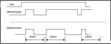
● The BCM starts timing when the rear defrosting lamp lights. After twenty minutes, it controls to disconnect the defrosting relay in the low voltage terminal box. The defrosting stops working and rear defrosting lamp is put out.
● When the rear defrosting lamp is lit, close defrosting function manually within twenty minutes. If opening it again, the BCM starts timing.


|
Connector number |
G14 |
|
Connector name |
Rear defrost heating wire |
|
Connector type |
ST710506-3 |
Left front rearview mirror
|
Connector number |
D02 |
|
Connector name |
Left front rearview mirror |
|
Connector type |
68508-0811[Molex](black) |
|
Terminal number |
Wire color |
Signal name |
|
6 |
LW |
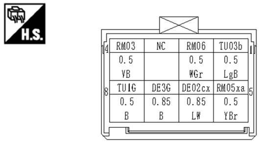
DE02cx Defrosting Power Supply for Rear View Mirror |
|
7 |
B |
DE3G rearview mirror defrosting and grounding |
Right front rearview mirror
|
Connector number |
D11 |
|
Connector name |
Right front rearview mirror |
|
Connector type |
68508-0811[Molex](black) |

|
Terminal number |
Wire color |
Signal name |
|
6 |
LW |
DE02bx Defrosting Power Supply for Rear View Mirror |
|
7 |
B |
DE2G rearview mirror defrosting and grounding |
Air conditioning controllerconnector
|
Connector number |
M13 |
|
Connector name |
A/C panel |
|
Connector type |
AMP1376113-1 |
|
Terminal No. |
Wire color |
Signal name |
|
A25 |
BrV |
BB07 rear defrost request |
|
A26 |
WB |
DE02a rear defrost feedback |
|
Connector number |
M08 |
|
Connector name |
Body control module C2 |
|
Connector type |
284972-1(black) |

|
Terminal No. |
Wire color |
Signal name |
|
38 |
BrV |
BB07 |
BCM模块C2
|
Connector number |
M09 |
|
Connector name |
Body control module C2 |
|
Connector type |
316371-1(white) |
|
Terminal number |
Wire color |
Signal name |
|
29 |
Lg |
DE03 |
Malfunction of rear window defrosting
1 Check the defrosting button on the touch panel
Does it work smoothly?
If yes>>Refer to second
If no>>Repair or replace the touch panel
2 Check the defrosting relay
If yes>>Refer to the third
If no>>Repair or replace the defrosting relay
3 Check rear window glass heater
Does it work smoothly?
If yes>>Refer to the fourth
If no>>Refer to chapter of “Inspection and maintenance for rear window glass heater”
4 Operate again and confirm result
Does it work smoothly?
If yes>> Finish
If no>>Refer to the first.
Malfunction of outside rearview mirror glass
1 Check the defrosting button on the touch panel
Does it work smoothly?
If yes>>Refer to the second
If no>>Repair or replace the touch panel
2 Check the defrosting relay
If yes>>Refer to the third
If no>>Repair or replace the defrosting relay
3 Check the outside rearview mirror glass heater
Does it work smoothly?
If no>>Refer to the fourth
If no>>Repair or replace outside rearview mirror glass heater
4 Operate again and confirm result
Does it work smoothly?
If yes>>Finish
If no>>Refer to the first
Rear window glass heater
1 Use the direct voltage of the digital multimeter.
2 Make cycling test on middle voltage of each resistance fuse. The normal voltage is 6V.
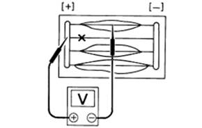
3 If the resistance fuse is burned, the multimter shows voltage of 12V or 0V.

4 To locate the burning point, move digital multimeter from left to right along the resistance fuse. When the digital multimeter pen approaches the burning point, the measured value will beat.
Conductive paint, ruler, pen, heating gun, alcohol, cotton cloth.
1 Use a cotton cloth pained with alcohol to wipe the damaged resistance wire and its surrounding area.
2 Use the pen nib to dip conductive paint. (The conductive paint should be shaken evenly before it is used ).
3 Put a ruler on a glass along the damaged resistance wire, slightly coat the damaged position with conductive paint by a pen nib and cover the intact resistance wire about 5mm respectively by both sides of the burning point.
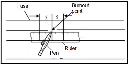
4 After maintenance is complete and conductive paint is solidified( about ten minutes), use a multimeter to check the damage repair effect.
Reminder:
When multimeter is testing, it is forbidden to touch the conductive paint repair position with hands or a tool.

![]()
5 When the test result is normal, use a heating gun to dry the repaired point. Keep the outlet of heating gun with the repaired point for more than 3cm and lasts about twenty minutes. If there is no heating gun available, you can choose to dry it by air which may last about twenty four hours.
