Safety Precaution
the electrical technicians who use medical electronic devicesprecautions
Warning:
● Strong magnetic components have been assembled on this vehicle
● Technicians shouldn't operate electronic pacemaker or other medical electronic devices in this vehicle, or the functions of medical devices may be affected by strong magnetic components.
Precautions for normal charging
Warning:
●
If a technician uses a medical electric device
such as an implantable cardiac pacemaker or an
implantable heart pacemaker defibrillator, the possible effects on the devices
must be checked before starting the charge operation.
●
If a technician using a medical electric device
such as implantable cardiac
pacemaker or an implantable heart pacemaker defibrillator .he must not enter
the vehicle compartment (including luggage room) during normal charge
operation.
Communication equipment operation precautions
1、 If the technician uses medical electronic devices such as cardiac pacemaker, cardioverter, defibrillator and other medical electronic equipment, please keep enough distance with the communication devices.
2、 The electromagnetic wave of the remote intelligent terminal may affect the function of the medical device such as cardiac pacemaker, cardioverter, defibrillator and other medical electronic devices.
3、 If the technician uses the medical device such as cardiac pacemaker, multiplexer, defibrillator and other medical electronic equipment, the electromagnetic wave of the remote intelligent terminal may affect the function of the device. The possible effect of the remote intelligent terminal on the medical electronic devices must be checked by the manufactures of the medical electronic devices .
Inspection of key points before the maintenance
The high-voltage system may automatically operate. Please confirm the remote air conditioning and fixed-time charging haven’t been set before the maintenance.
Attention:
If remote air-conditioning or fixed-time charging is set, the high voltage system will run automatically even the switch is off.
Precautions of auxiliary restraint system "airbag" and "seat belt pretension"
The
Supplemental Restraint System such as “AIR BAG” and “SEAT BELT PRE-TENSIONER”,
used along
with a front seat belt, helps to reduce the risk or severity of injury to the
driver and front passenger for certain types of collision. This system includes
seat belt switch inputs and dual stage front air bag modules. Information
necessary to service the system safely is included in the “SRS AIR BAG” and
“SEAT BELT” of this Service Manual.
Warning:
Always observe the following items for preventing accidental activation.
1 To avoid rendering the SRS inoperative, which could increase the risk of personal injury or death in the event of a collision that would result in air bag inflation, all maintenance must be performed by an authorized JAC dealer.
2
Improper maintenance, including incorrect
removal and installation of the SRS, can lead to personal
injury caused by unintentional activation of the system. For removal of Spiral
Cable and Air Bag Module, see “SRS AIR BAG”.
3 Do not use any electrical test devices to test any circuit of the auxiliary restraint system unless these tests are in the instructions described in the service manual. The wire harness and connectors of the auxiliary restraint system should adopt to yellow or orange color.
PRECAUTIONS WHEN USING POWER TOOLS (AIR OR ELECTRIC) AND HAMMERS
●
When working near the Air Bag Diagnosis Sensor Unit or other Air
Bag System sensors with the power switch ON, never use air or electric power
tools or strike near the sensor(s) with a hammer. Heavy vibration could
activate the sensor(s) and deploy the air bag(s), possibly causing serious
injury.
● When using power tools or a hammer, turn the key in the "LOCK" position, unplug the cathode of 12V lead-acid battery and wait at least 1 minute for maintenance.
Precautions of removing the 12V battery
When removing the 12V battery, turn the power switch to “ON”, and then to “OFF”.
Note:
1 The automatic 12V battery charge control may start even when the power switch is in OFF state.
2 The automatic 12V battery charge control does not start within approximately one hour when the power switch is turned ON/OFF.
● Before the repairing which no need the power: rotate the key to LOCK gear and disconnect the 12V battery negative.
● After disconnect the 12V battery negative, the memory of radio and other control devices will be cleared.
● Replace new oil seal, gasket,gasket ring,O ring,lock washer,cotter pins,self-locking nuts and other parts.
● Place the removed parts in order and according to the positions as they are assembled .
● If necessary, use approved binders, sealants or equivalent products.
● For safe and efficient repair work, you should use hand tools, power tools (disassembly only) and special tools.
● Before repairing the vehicle:
Cover the fender, interior and carpet with a suitable cover. Be careful do not scratch the paintwork with keys, buttons or something like this.
1、Tail door structure
Tail door structure decomposition
![]()
![]()
![]()


![]()
![]()
![]()
![]()
1、 tail door hinge 2、tail door air spring pole 3、tail door air spring pole bracket 4、tail door lock buckle 5、tail door lock body 6、tail door fixing dumper block 7、tail door adjustable dumper block 8、tail door rubber strip 9、tail door metal plate assembly
1、Tail door lock device

 |
 |
||||||||||


 |
2、Tail door locating mechanism


 |

3、Tail door hinge device


 |
|||||||||


2、 Front cabin cover structure 
Front cabin cover structure decomposition
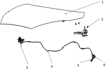
1、front cabin cover assembly 2、front cabin cover hinge 3、front cabin lock 4、front cabin drawbench 5、 front cabin cover open handle 6、front cabin cover open handle base assembly
1、Front cabin cover lock device


 |
|||
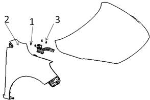
2、Front cabin cover hinge device

 |
3、charging port cover structure
● Prevent damage or scratch while disassembling or assembling parts
● In the disassembly of some larger components, ensure at least two people should operate in case of parts fall-off.
● When installing plastic parts, make sure the screws are installed in the mounting holes first,and then carefully tighten the screws.
● The charging cover relates to electrical components.Please put the key in the “LOCK before installing it.
1.Left electric actuator 2.charging port cover assembly 3.lock actuator of the cover 4.the left cover mounting bracket 5.the right cover mounting bracket 6.right electric actuator 7.11293-0616F71 hex bolt and flat spring washer assembly 8.12493-0412F71 M type sunk screw 9.11293-0620F62 hex bolt and flat spring washer assembly 10.12493-0512F38 M type sunk screw 11.charging port cover actuator clip connector
2.Adjustment and replacement of charging port cover assembly
Adjustment
of charging port cover:
●
Take
down front bumper, Refer to “front bumper ![]()
![]()
assembly replacement”.
●
Use
cross screwdriver to disassemble the ![]()
![]()
charging port cover fixing screws;
● Adjust the charging port cover to the appropriate
position, and ensure the cooperation with the front bumper.
Gap uniform:
● Fasten screws with the cross screwdriver.
●
Tightening torque: (7±2)N.m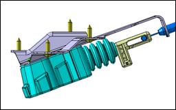
●
Install
front bumper, Refer to “front bumper 
assembly replacement”.
Attention:
● The charging port cover must be closed during
the installation;
● Remove the front bumper assembly and then pull this embossment to open the cover.
Replacement of charging port cover:
Disassembly: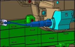
● Disassemble front bumper, Refer to “front
bumper replacement”.
Charging
port cover;![]()
● Turn the charging port cover lock actuator
clockwise and pull it out,
Place and preserve the cover actuator well after Disassembling the actuator
All the two side actuators need to be disassembled;
● Use cross screwdriver to disassemble the charging port cover fixing screws;
● Disassemble the charging port cover,refer to “Replacement of charging port cover”.
Assembly:
Follow the opposite sequence of the disassembly procedures.
Replacement of charging port lock actuator:
Disassembly:
●
Disassemble
front bumper, Refer to “front 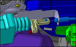
bumper replacement”.
And open charging port cover;
●
Turn the charging
port cover lock actuator clockwise 
![]()
and pull it out,
Place and preserve the cover actuator well after
Disassembling the actuator
All the two side actuators need to be disassembled;
● Remove the drawbench connector from the slot.
And take down the cylinder pin head from the slot.
Assembly:
Follow the opposite sequence of the disassembly procedures.
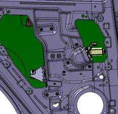
Replacement
of charging port cover electric actuator assembly: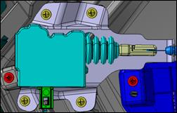
![]()
![]()
Disassembly:
● Disassemble front bumper, Refer to “front
bumper replacement”.
And open charging port cover;
●
Remove
the drawbench connector from the slot.![]()
![]()
And take down the cylinder pin head;
● Disconnect the connector of electric actuator.
● Use cross screwdriver to disassemble the four fixing screws of electric actuator.
Assembly:
Follow the opposite sequence of the disassembly procedures.
Attention:
● After the installation is completed, start the vehicle and press the charging port cover starting switch, and confirm that the actuator normally operates and open the charging port cover;
● The electric actuators differentiates the left and right sides, Pay attention to confirm that when installing.
● Confirm the drawbench is clamped into the slot completely when clamping the drawbench,in case of falling off late at work.
Replacement of charging port cover mounting bracket:
Disassembly:
●
Take
down front bumper, Refer to “front bumper 

![]()
assembly replacement”;
● Disassemble the bracket installed on the front
module with socket spanner
.
Assembly:
Follow the opposite sequence of the disassembly procedures.
Attention:
● When mounting the bracket, notice that the left side of the support lower end has a drawbench, and it should be careful not to press it.
4、Door structure
Door decomposition
Attention:
■The doors assembly methods are the same.
■When disassembling and assembling the door assembly, take good guard against the door and body scratch.
■After the door assembly is complete,it must to adjust to ensure the door open and close normally,The head of the hinge assembly bolt is also repainted(car body color).
■Inspect whether the hinge rotating part exists poor lubrication or not. Apply lubrication grease if necessary.
■Because of the heavy weight of door parts,The disassembly process requires a lot of cooperation with multiplayer.
Replacement of front door stopper:
1) disassembly
①Remove the fixing bolt connecting the body and the stopper with a 12mm socket spanner.
■tightening torque: 16.7~25.5 N•m
② Remove 2 fixing bolts connecting the door and the stopper with a 10mm socket spanner.
■ Tightening torque:7.8~11.8 N•m
 |
1) Assembly
Follow the opposite sequence of the disassembly procedures.
Replacement of front side door hinge assembly
1) disassembly
① Disassemble door stopper, Refer to “door stopper replacement”;
② Remove the fixing bolt connecting the door and the hinge with a 12mm socket spanner.
■ Tightening torque:29~35 N•m
 |
Attention:
■Disassembly should be done in several times. Do not loosen all parts in one time.
■Please disassemble from lower part to upper part.
③ unplug the rubber sleeve of door harness, then unplug the door’s electric connector.
④ lift down vehicle door with assistance of other people.
2) assembly
Follow the opposite sequence of the disassembly sequence.
Attention:
■ tightening should be done in several times during the installation. Do not tighten all bolts well in one time.
Replacement of front door hinge
1) disassembly
① Remove the front side door assembly Refer to “Replacement of front side door assembly”
② Remove the fixing bolt connecting the body and the hinge with a 12mm socket spanner.
■ Tightening torque:29~35 N•m

■ Assembly
Follow the opposite sequence of the disassembly procedures.
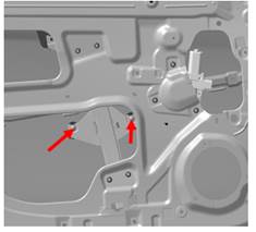
Replacement of front door waterproof membrane:
1) disassembly
① Disassemble door inner trim panel.
② Disassemble wire harness fixing buckle.
③ separate waterproof membrane and take it down.
2) assembly
Follow the opposite sequence of the disassembly procedures.
Attention:
■Do not touch the surface of the adhesive to reduce the effect of the reattachment weakening.
■Be careful when taking down the waterproof membrane, so as not to damage the waterproof membrane.
 |
Replacement of front door lock assembly:
1) Disassembly
① Disassemble front door inner trim panel.
② disassemble water-proof membrane
③ Disassemble the front door window guide rail
④ disconnect lock connector.
⑤ disassemble the fixing bolt of lock assembly.
⑥ disconnect the connection between door outward rod and lock.
⑦ take out lock assembly(tightening torque 8±1N.m).
2) assembly
Follow the opposite sequence of the disassembly sequence.
Attention:
■the parts must be installed on the original position during installation.
■ after assembly, check whether door’s opening and closing are normal, and the locking should be firm If not, please adjust or re-assemble the lock
 Replacement of front door lock
buckle
Replacement of front door lock
buckle
1) disassembly
① mark the position of current lock buckle
② disassemble fixing bolt of lock buckle (tightening torque 15.5±2N.m).
③ disassemble lock buckle
2) assembly
Follow the opposite sequence of the disassembly sequence.
Adjustment of front door lock buckle
① loosen the buckle’s screw
② move the buckle to the needed direction. Ensure the buckle is in the middle of door lock.
③ tighten the fixing bolt of buckle
④ close door and check whether side difference and clearance meet the demand.
Note:
replacements of components on left and right front door
are the same.
Replacement of inner weather-strip of front side door
1) disassembly
① Disassemble door inner trim panel. Refer to “replacement of front side door inner trim panel”.
② pull out one end of the weather-strip,take it down slowly.
Attention:
■ Do not exert too much force when disassembling , which may cause parts’ deformation;
2) assembly
① Make the front side door inner weather-strip align to the B column, keep the gap 1~2mm, install the rear end first, and then slowly install the weather-strip well.
Replacement of outer weather-strip of front door window
1) disassembly
① Descend the door glass to the lower end.
② unscrew the fixing screws of outer weather-strip of front door
 |
③ Disassemble outer weather-strip of front door
Attention:
■ Do not exert too much force when disassembling , which may cause parts’ deformation;
■Check the weather-strip in vision after disassembly,if there is deformation found,please replace it.
2) assembly
① Make the front side door outer weather-strip align to the B column frame, and then slowly install the weather-strip well from one end.
 |
② fasten the fixing screws of outer weather-strip of front side door,tightening torque:3~5N.m.
Replacement of front door window
1) disassembly
① Disassemble door inner trim panel. Refer to “replacement of front door inner trim panel”.
② disassemble water-proof membrane Refer to “Replacement of front door waterproof membrane”.
③ disassemble inner weather-strip of front side door. Refer to “Replacement of inner weather-strip of front side door”
④ install the window regulator switch back,lift the window to the appropriate location,
be easy to disassemble the fixing screw for front door window.
⑤ Disassemble the fixing screw for front door window.
⑥ unscrew the fixing bolt of the front door window glass guide rail
⑦ take down the door window glass.
2) assembly
① install the window regulator switch back,lift the window to the middle location,be easy to install the glass in the regulator.
② put the window glass in the door,lift the glass to the top.
③ install the fixing screw,fasten the glass guide rail fixing bolt,tightening torque:9±2N.m.
④ install inner weather-strip of front side door Refer to “inner weather-strip of front side door”
⑤ install waterproof membrane. Refer to “Replacement of front door waterproof membrane”.
⑥ Install the front door inner trim panel. Refer to “replacement of front door inner trim panel”.
Replacement of front door window glass regulator
1) disassembly
① Disassemble door inner trim panel. Refer to “replacement of front door inner trim panel”.
② disassemble water-proof membrane Refer to “Replacement of front door waterproof membrane”.
③ disassemble inner weather-strip of front side door. Refer to “inner weather-strip of front side door”
④
Disassemble window glass。 Refer to”Replacement of front
door window glass”
⑤ disassemble the fixing nuts of glass bracket.
⑥ disassemble the fixing nuts of glass regulator
motor.
⑦ Disconnect the harness connector of the
glass regulator motor.
⑧ Take out the glass regulator.
2) assembly
① connect the harness connector of glass regulator, put in glass assembly.
① Install the fixing nuts of front door window glass. Tightening torque: 9 ± 2N.m
③ Install the fixing nuts of front door window regulator motor. Tightening torque: (9±2)N.m
③ Install door glass. Refer to”Replacement of front door window glass”
⑤ install inner weather-strip of front side door Refer to “Replacement of inner weather-strip of front side door”
⑥ install waterproof membrane. Refer to “Replacement of front door waterproof membrane”.
⑦ Install the front door inner trim panel. Refer to “replacement of front door inner trim panel”.
Replacement of front door window glass groove
1) disassembly
① Disassemble door inner trim panel. Refer to “replacement of front door inner trim panel”.
② disassemble water-proof membrane Refer to “Replacement of front door waterproof membrane”.
③ disassemble inner weather-strip of front side door. Refer to “inner weather-strip of front side door”
④ Disassemble outer weather-strip of front door window. Refer to “Replacement of outer weather-strip of front door window”
⑤ Disassemble window glass Refer to”Replacement of front door window glass”
⑥ Disassemble the front door guide rail
 |
⑦ Disassemble front door guide rail,quarter window,groove.
⑧ Disassemble front door window glass groove.
2) assembly
① After preloading the front door guide rail,quarter window and glass regulator,install them on the door.
② Install outer weather-strip of front door window. Tightening torque: (3~5)N.m Refer to “outer weather-strip of front door window”.
③ Install the glass regulator of front side door Refer to “Replacement of front door window glass regulator”. Tightening torque: (7~11)N.m
③ Install door glass. Refer to”Replacement of front door window glass”
⑤ install inner weather-strip of front side door Refer to “Replacement of inner weather-strip of front side door”
⑥ install waterproof membrane. Refer to “Replacement of front door waterproof membrane”.
⑦ Install the door inner trim panel. Refer to “replacement of front door inner trim panel”.
Replacement of front door window glass lower guide rail
1) disassembly
① Disassemble door inner trim panel. Refer to “replacement of front door inner trim panel”.
② disassemble water-proof membrane Refer to “Replacement of front door waterproof membrane”.
③ disassemble inner weather-strip of front side door. Refer to “inner weather-strip of front side door”
④ Disassemble outer weather-strip of front door window. Refer to “Replacement of outer weather-strip of front door window”
⑥ Disassemble window glass Refer to”Replacement of front door window glass”
⑦ Pull out the lower guide rail groove.
⑧ loosen the fixing bolt of lower guide rail,take down the guide rail

2) assembly
① install the guide rail,tighten the fixing bolt,tightening torque is (6~10)N.m
② install front door window glass regulator groove,install the two connecting feet first
③ Install the glass regulator of front side door Refer to “Replacement of front door window glass regulator”. Tightening torque: (7~11)N.m
③ Install door glass. Refer to”Replacement of front door window glass”
⑤ Install outer weather-strip of front door window. Tightening torque: (3~5)N.m Refer to “outer weather-strip of front door window”.
⑥ install inner weather-strip of front side door Refer to “Replacement of inner weather-strip of front side door”
⑦ install waterproof membrane. Refer to “Replacement of front door waterproof membrane”.
⑧ Install the front door inner trim panel. Refer to “replacement of front door inner trim panel”.
Replacement of rear door stopper
1) disassembly
①Remove the fixing bolt connecting the body and the stopper with a 12mm socket spanner.
■tightening torque: 16.7~25.5 N•m
② Remove 2 fixing bolts connecting the door and the stopper with a 10mm socket spanner.
■ Tightening torque:7.8~11.8 N•m
2) assembly
Follow the opposite sequence of the disassembly procedures.
Replacement of rear side door hinge assembly
1) disassembly
① Disassemble door stopper, Refer to “door stopper replacement”;
② Remove the fixing bolt connecting the door and the hinge with a 12mm socket spanner.
■Tightening
torque:29~35 N•m
Attention:
■Disassembly should be done in several times. Do not loosen all parts in one time.
■Please disassemble from lower part to upper part.
③ unplug the rubber sleeve of door harness, then unplug the door’s electric connector.
④ lift down vehicle door with assistance of other people.
2) assembly
Follow the opposite sequence of the disassembly sequence.
Attention:
■ tightening should be done in several times during the installation. Do not tighten all bolts well in one time.
Replacement of rear door hinge
1) disassembly
① Remove the front side door assembly Refer to “Replacement of front side door assembly”
② Remove the fixing bolt connecting the body and the hinge with a 12mm socket spanner.
■ Tightening torque:29~35 N•m
■ Assembly
Follow the opposite sequence of the disassembly procedures.
Replacement of rear door waterproof membrane:
1) disassembly
① Disassemble rear door inner trim panel.
② Disassemble wire harness fixing buckle.
③ separate waterproof membrane and take it down.
2) assembly
Follow the opposite sequence of the disassembly procedures.
Attention:
■When assembling the waterproof membrane, the waterproof membrane should not be allowed to cover the mounting hole of the door trim panel.
■Do not touch the surface of the adhesive to reduce the effect of the reattachment weakening.
Replacement of rear door lock assembly
1) disassembly
① Disassemble rear door inner trim panel.
②disassemble water-proof membrane
③ Pull out the connector
④ Pull out the lower guide rail groove.
⑤ disassemble glass guide rail
⑥ disassemble the fixing bolt of lock assembly.
⑦ disconnect the connection between door outward rod and lock.
⑧ pull out lock body assembly
2) assembly
Follow the opposite sequence of the disassembly procedures.
Note:
Hint: replacement of components on left and right rear door are the same. Please lift the glass to the highest point before disassembling.
Replacement of inner weather-strip of rear side door
1) disassembly
① Disassemble door inner trim panel. Refer to “replacement of rear front side door inner trim panel”.
②
pull out one end of the weather-strip,take it down slowly.
Attention:
■ Do not exert too much force when disassembling , which may cause parts’ deformation;
2) assembly
① Make the rear side door inner weather-strip align to the B column, keep the gap 1~2mm, install the front end first, and then slowly install the weather-strip well.
Replacement of outer weather-strip of rear door window
1) disassembly
① Descend the door glass to the lower end.
② unscrew the two fixing screws of outer weather-strip of door
③ Disassemble outer weather-strip of rear door
Attention:
■ Do not exert too much force when disassembling , which may cause parts’ deformation;
2) assembly
①
Make the front side door outer weather-strip align to the B column frame, and
then slowly install the weather-strip well from one end.
② fasten the fixing screws of outer weather-strip of rear side door,tightening torque:3~5N.m.
Replacement of rear door window
1) disassembly
① Disassemble door inner trim panel. Refer to “replacement of rear front door inner trim panel”.
② disassemble water-proof membrane Refer to “Replacement of rear door waterproof membrane”.
③ Disassemble outer and inner weather-strip of rear side door Refer to “Replacement of inner and outer weather-strip of rear side door”
④ install the window regulator switch back,lift the window to the appropriate location,be easy to disassemble the fixing screw of rear door window glass.
⑤ Disassemble the fixing screw of rear door window.

⑥ Disassemble the fixing screw of rear door window glass lower guide rail.
⑦ take down the door window glass.
2) assembly procedures:
① install the window regulator switch back,lift the window to the appropriate location,be easy to install the fixing screw of door window glass.
② put the window glass in the door,align to the mounting hole.
③ install the fixing screw of door window glass,tightening torque:(7~11)N.m.
① install lower fixing bolt of the rear guide rail,tightening torque is (6~10)N.m
⑤ install inner weather-strip of rear side door Refer to “Replacement of inner weather-strip of rear side door”
⑥ install waterproof membrane. Refer to “Replacement of rear door waterproof membrane”.
⑦ Install the front door inner trim panel. Refer to “replacement of rear front door inner trim panel”.
Replacement of rear door window glass regulator
1) disassembly
① Disassemble door inner trim panel. Refer to “replacement of rear front door inner trim panel”.
② disassemble water-proof membrane Refer to “Replacement of rear door waterproof membrane”.
③ disassemble inner and outer weather-strip of rear side door. Refer to “inner and outer weather-strip of rear side door”
④ Disassemble window glass Refer to”Replacement of rear door window glass”
⑤ Disconnect the harness connector of the glass regulator motor.
⑥ disassemble the fixing nuts of glass bracket.
⑦ disassemble the fixing nuts of glass regulator motor.
⑧ Take out the glass regulator.
![]()
![]()
![]()
![]()
![]()
![]()
![]()
2) assembly
① put glass regulator in,install fixing nuts of rear door window glass bracket. Tightening torque: (7~11)N.m
② Install the fixing nuts of rear door window regulator motor. Tightening torque: (7~11)N.m
Install rear door window glass. Refer to”Replacement of rear door window glass”
④ connect the harness connector of rear door window glass regulator.
⑤ install waterproof membrane. Refer to “Replacement of rear door waterproof membrane”.
⑥ install inner and outer weather-strip of rear side door Refer to “Replacement of inner and outer weather-strip of rear side door”
⑦ Install the front door inner trim panel. Refer to “replacement of rear front door inner trim panel”.
Replacement of rear door window glass groove
1) disassembly
① Disassemble door inner trim panel. Refer to “replacement of rear front door inner trim panel”.
② disassemble water-proof membrane Refer to “Replacement of rear door waterproof membrane”.
③ disassemble inner weather-strip of rear side door. Refer to “Replacement of inner weather-strip of rear side door”
④ Disassemble window glass Refer to”Replacement of rear door window glass”
⑤ Disassemble outer weather-strip of rear door window. Refer to “Replacement of outer weather-strip of rear door window”
⑥ Disassemble rear door window glass groove.
 |
2) assembly
① install rear door window glass regulator groove,install the two connecting feet first
② Install door widow glass. Refer to”Replacement of rear door window glass”
③ install inner weather-strip of rear side door. Refer to “Replacement of inner weather-strip of rear side door”
④ Install outer weather-strip of front door window. Tightening torque: (3~5)N.m Refer to “outer weather-strip of rear door window”
⑤ install waterproof membrane. Refer to “Replacement of rear door waterproof membrane”.
⑥ Install the front door inner trim panel. Refer to “replacement of rear front door inner trim panel”.
Replacement of rear door window glass lower guide rail
1) disassembly
① Disassemble door inner trim panel. Refer to “replacement of rear front door inner trim panel”.
② disassemble water-proof membrane Refer to “Replacement of rear door waterproof membrane”.
③
install glass regulator back,lift the glass to the top.
④ Pull down the lower guide rail glass
groove.
⑤ loosen the two fixing bolts of lower
guide rail,take down the guide rail
2) assembly
① Install lower guide rail,fasten the upper fixing bolt,don’t fasten the lower fixing bolt temporarily. Tightening torque: (6~10)N.m
② install rear door window glass regulator groove,install the two connecting feet first
③ Install door window glass. Refer to”Replacement of rear door window glass”
④ fasten the lower fixing bolt of guide rail. Tightening torque: (6~10)N.m
⑤ install inner weather-strip of rear side door Refer to “Replacement of inner weather-strip of rear side door”
⑥ Install outer weather-strip of front door window. Tightening torque: (3~5)N.m Refer to “outer weather-strip of rear door window”
⑦ install waterproof membrane. Refer to “Replacement of rear door waterproof membrane”.
⑧ Install the front door inner trim panel. Refer to “replacement of rear front door inner trim panel”.
Replacement of door electric window anti-pinch controller
1) Disassembly procedures
① Disassemble the auxiliary dashboard,refer to “auxiliary dashboard”.
② disconnect the connector between window anti-pinch controller and the wire harness.
③ loosen the four fixing bolts of window anti-pinch controller,take down the controller.
![]()
![]()
![]()
![]()
2) Disassembly procedures
① put in window anti-pinch controller,fasten the four mounting bolts,tightening torque(7~11)N.m.
② connect the two connectors of window anti-pinch controller.
③ Install the auxiliary dashboard.