Electrical Instrument-
Safety Precaution....................................................................................................................................... 3
Precaution for supplemental restraint system "airbag" and "safety belt pretension"............... 3
Introduction
Please abide by the following precaution measures, to ensure carrying out maintenance service safely and correctly.
Precaution for engineer using medical electronics
Warning:
● The vehicle has strong magnetic parts.
● If an engineer uses medical electronic device, such as electronic pacemaker, it is forbidden for him to operate on the vehicle. Otherwise, the function of the electronic device may be affected by the strong magnetic parts.
Precaution for normal charge
Warning:
● If an engineer uses medical electronic devices including heart pacemaker, cardioverter, defibrillator, the device can be only be used after its function being checked and confirmed before starting normal operations.
● During normal charge operation, the medical electronic device may be affected by electromagnetic wave. An engineer who uses medical electronic devices including heart pacemaker, cardioverter, defibrillator cannot enter passenger compartment (including trunk).
Precaution for communication device operation
l If an engineer uses medical electronic devices including heart pacemaker, cardioverter, defibrillator, please keep enough distance with communication device.
l The function of medical electronic devices including heart pacemaker, cardioverter, defibrillator may be affected by the electromagnetic wave of remote intelligent terminal.
l If an engineer uses medical electronic devices including heart pacemaker, cardioverter, defibrillator, the electromagnetic wave of remote intelligent terminal may affect its function. It is mandatory to request the medical electronic device manufacturer to check and confirm the possible effect on medical electronic device when using remote intelligent terminal.
Critical point check before maintenance
As high-voltage system may automatically activate, please confirm not setting remote air conditioning or timed charging before maintenance.
Caution:
If setting remote conditioning or timed charging, high-voltage system may also automatically start working even though the switch is OFF.
Precaution for supplemental restraint system "airbag" and "safety belt pretension"
Supplemental restraint system “airbag” and “safety belt pretension” is used together with front seat safety belts, which can reduce the damage to the driver and front passenger during collision. Supplemental restraint system consists of safety belt, driver airbag, and front passenger airbag. The detailed information of supplemental restraint system is included in the chapters of airbag system and seat safety belt.
Warning:
In order to avoid accidents, please abide by the following content:
l To avoid the failure of supplemental restraint system and considering that the risk of physical injuries will increase during collision if the system fails, all the service must be executed by JAC authorized dealer.
l Non-normative maintenance of supplemental restraint system including non-normative removal and installation may result in accidental trigger of the system and cause physical injuries. Regarding the method of removing airbag module, please refer to Airbag System chapter.
l Except for the operations in the service manual, please do not use electrical test device to test any circuit of supplemental restraint system. The color of harness and connector of supplemental restraint system is yellow or orange.
Precaution for using power tool (pneumatic or electric) and hammer
l When power switch is at “ON” position and approach airbag diagnosis sensor or other sensors of airbag system, please do not use power tools or hammer on the sensor part area. Violent vibration may trigger these sensors and airbag to cause serious injuries.
l When using power tools or hammer, put the key at “LOCK” position, unplug the negative pole of 12V lead-acid battery, wait at least one minute, and then start maintenance.
Precaution for removing 12V battery
Before removing 12V battery, turn the key to “ON” position, and then turn to “LOCK” position.
Reminder:
l Though the key is at “LOCK” position, auto-recharge function of 12V battery may activate.
l After the key turns from “ON” to “LOCK”, auto-recharge function of 12V battery will not activate.
General tool
|
Tool name |
Description |
|
Power tool
|
Loosen bolt |

Electrical Instrument-
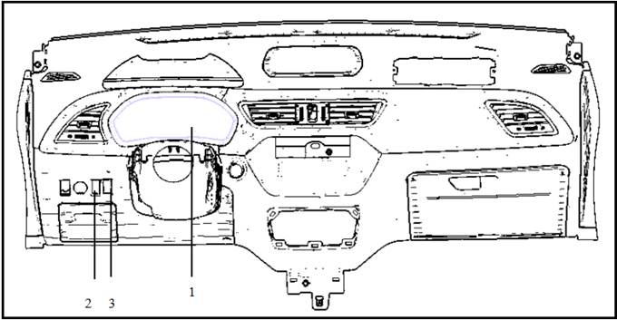
Part position
|
SN |
Part name |
Description |
|
1 |
Electrical Instrument- |
Refer to “Electrical instrument system-constituent component” |
|
2 |
Light control switch |
Refer to “Electrical instrument system-control switch” |
|
3 |
TRIP switch |
Refer to “Electrical instrument system-control switch” |
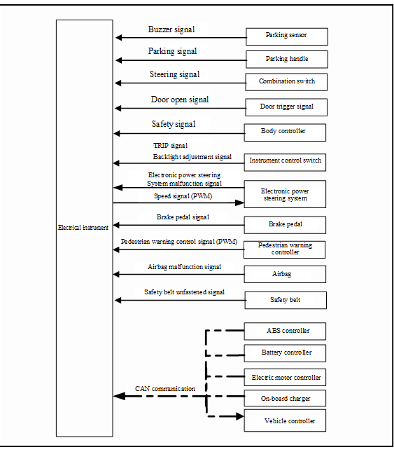
Electrical instrument controls following items through each controller CAN signal, switch signal and sensor signal.
l Vehicle speed meter
l Battery meter
l Battery available capacity meter
l Battery temperature meter
l Power meter
l Odometer
l Indicator lamp
l Warning lamp
l Instrument illumination control
l Information display
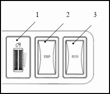
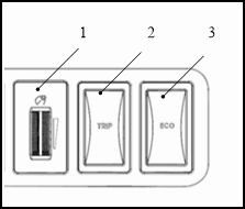
Instrument control switch
Instrument control switch is located at the left side of switch group on cluster and controls following functions.
|
SN |
Switch name |
Description |
|
1 |
Backlight adjustment knob |
Adjust instrument backlight. |
|
2 |
TRIP switch |
Reset electrical instrument tripmeter. |
|
3 |
ECO switch |
ECO mode selection switch. |
l Send following signals to electrical instrument
- Backlight adjustment knob signal
- TRIP reset switch signal
- ECO trigger switch
Electrical instrument introduction

Electrical instrument input signal (CAN communication)
|
Signal source |
Signal name |
|
ABS controller |
|
|
Vehicle controller |
Electric motor malfunction warning lamp signal |
|
Battery malfunction warning lamp signal |
|
|
System malfunction warning lamp signal |
|
|
Limit power indicator lamp signal |
|
|
High voltage cut-off indicator lamp signal |
|
|
READY indicator lamp signal |
|
|
Average electricity consumption signal |
|
|
Energy flow signal |
|
|
Remainder range signal |
|
|
Battery capacity signal |
|
|
Battery temperature signal |
|
|
Battery available capacity signal |
|
|
Electric motor power signal |
|
|
Gear information signal |
|
|
ECO gear signal |
|
|
Charging wire connection indicator lamp signal |
|
|
Charging status indicator lamp signal |
|
|
Electric motor controller |
Tachograph signal |
Electrical instrument output signal (CAN communication)
|
Vehicle controller/remote intelligent terminal |
Total mileage |
Electrical instrument output signal
|
Receive signal component |
Signal name |
|
Speed signal |
|
|
Acoustical signal |
Door open warning signal |
|
Vehicle running warning signal |
|
|
Safety belt unfastened signal |
|
|
Critical CAN signal lost alarm |
Description
Electrical Instrument-
l Electrical instrument collects signals from control unit, switch and sensor, and controls following functions.
- Travel mileage display
- Warning lamp
- Indicator lamp
- Electrical instrument backlight control
- Electrical instrument effect function
- Information display
l Electrical instrument has buzzer function and can send alarm sound.
Electrical instrument function list
|
System |
Description |
|
|
Measuring meter |
Battery temperature meter |
Display power battery temperature. |
|
Battery meter |
Display power battery remainder capacity. |
|
|
Battery available capacity meter |
Display power battery available capacity. |
|
|
Electric motor power meter |
Display following power situation. l Current electric motor power l Maximum electric motor output power l Maximum energy recovery power |
|
|
Speedometer |
Display current speed. |
|
|
Instrument illumination control |
Instrument illumination control function |
Control display backlight. |
|
Indicator lamp |
Instrument control indicator lamp function |
Control instrument indicator lamp display. |
|
READY function |
READY indicator lamp |
When the vehicle is in travelling status, READY indicator lamp is always ON. |
|
Information display |
Total mileage display |
Display total mileage. |
|
TRIP mileage display |
Display trip mileage. |
|
|
Gear display |
Display gear (including ECO gear). |
|
|
Average energy consumption |
Display average energy consumption. |
|
|
Energy flow display |
Display energy flow direction and status. |
|
|
Door open display |
Display when any door opens. |
|
|
Statement reminder |
Vehicle-in-danger, vehicle pull-over, trouble lamp, leave immediately |
Display when the vehicle is under potential safety risk. |
|
Limit power mode |
Display when vehicle enters limit power status. |
|
|
Display when vehicle needs to be pulled over. |
||
|
Battery temperature extremely low |
Display when power battery temperature is extremely low. |
|
|
Go to 4S showroom for maintenance! |
Display when vehicle need maintenance. |
|
|
Charging wire connecting! |
Display when the key is at ON position and charging wire is being connected. |
|
|
Turn back to N gear, then READY. |
Display when the key is turned to “START” at D or N gear. |
|
|
Press brake pedal |
Display before shifting gear. |
|
|
Release hand brake |
Display when it is necessary to release hand brake. |
|

Electrical instrument electrical schematic diagram
Electrical instrument failure-safety
“Failure-safety” mode list
When malfunction occurs in CAN communication between electrical instrument and other controllers, trouble shooting will be activated.
|
Strategy |
||
|
Do not display. |
||
|
Battery temperature meter |
||
|
Battery meter |
||
|
Battery available capacity meter |
||
|
Electric motor power meter |
||
|
Liquid crystal display |
Gear |
Display “N” gear. |
|
TRIP mileage |
Record lost during this vehicle operation. |
|
|
Total mileage |
||
|
Energy flow |
Display vehicle parking interface. |
|
|
Average energy consumption |
Do not display. |
|
|
Warning lamp/indicator lamp |
ABS malfunction warning lamp signal |
Indicator lamp goes out. |
|
Electric motor malfunction warning lamp signal |
||
|
Battery malfunction warning lamp signal |
||
|
System malfunction warning lamp signal |
||
|
Front fog lamp |
Limit power indicator lamp signal |
|
|
High voltage cut-off indicator lamp signal |
||
|
READY indicator lamp signal READY |
||
|
Charging wire connection indicator lamp signal |
||
|
Charging status indicator lamp signal |
||
 Description
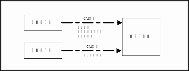
l Electrical instrument receives electric motor controller rotation speed signal and calculates into speed signal. Vehicle speed value is displayed on instrument.
l Electrical instrument sends calculated speed signal value to electronic power steering system controller, which adjusts steering power according to speed signal value.
Signal path
|
Signal name |
Signal path |
|
Electric motor controller (rotation speed signal)→Electrical instrument (speed signal)→Electronic power steering system controller |
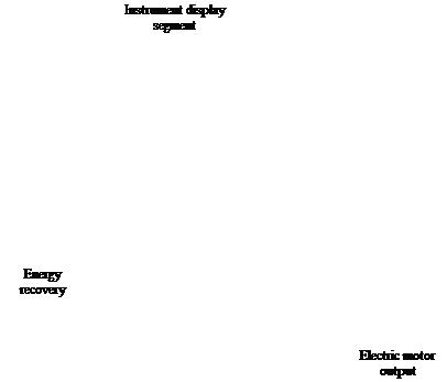
Power meter system description
System schematic diagram


Description
l Power level can be displayed on electrical instrument power meter
- Current electric motor power
- Electric motor maximum output power
- Maximum energy recovery power
l Electric motor controller transmits electric motor rotation speed and torque data to vehicle controller through CAN communication. Vehicle controller calculates electric motor power value.
l Vehicle controller transmits electric motor power to electrical instrument for display.
- Current electric motor power signal value
- Electric motor maximum output power signal value
- Maximum energy recovery power signal value
l Based on CAN signal received from vehicle controller, power value is displayed on instrument power meter.
Signal path
|
Signal name |
Signal path |
|
Current electric motor power signal value |
Electric motor controller (Electric motor rotation speed and torque signal)→Vehicle controller (Electric motor output power signal)→Electrical instrument |
|
Electric motor maximum output power signal value |
|
|
Maximum energy recovery power signal value |
Electrical instrument power meter function list
|
|
Function |
Description |
Signal name |
|
1 |
Black round dot displays current electric motor power and energy recovery power. |
Electric motor power signal |
|
|
2 |
Maximum electric motor output power |
||
|
3 |
Display maximum electric motor output power. |
Fixed value |
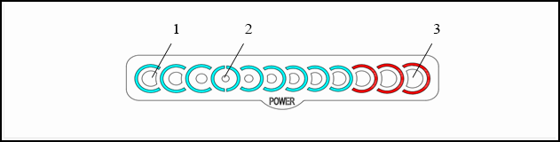
Display bar parameter comparison table
Electrical instrument power meter display/go-out segment

Power meter display segment number and power value table
|
Display segment number |
Power(kw) |
- |
|
|
9 |
Electric motor output power |
72 |
P9 |
|
8 |
64 |
P8 |
|
|
7 |
56 |
P7 |
|
|
6 |
48 |
P6 |
|
|
5 |
40 |
P5 |
|
|
4 |
32 |
P4 |
|
|
3 |
24 |
P3 |
|
|
2 |
16 |
P2 |
|
|
1 |
8 |
P1 |
|
|
0 |
- |
0 |
0 |
|
1 |
Energy recovery |
6 |
P-1 |
|
2 |
12 |
P-2 |
|
|
3 |
18 |
P-3 |
|
|
4 |
24 |
P-4 |
|
System schematic diagram
Battery temperature signal Battery temperature signal Vehicle controller CAN communication Electrical instrument CAN communication Electric motor controller
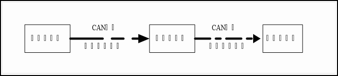
Description
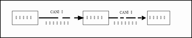
● Battery controller transmits battery temperature signal to vehicle controller through CAN communication. After dealing with the signal, vehicle controller transmits battery temperature signal to electrical instrument through CAN signal. Electrical instrument displays battery temperature information on battery temperature meter.
● Electrical instrument displays battery temperature information on battery temperature meter.
Signal path
|
Signal name |
Signal path |
|
Battery temperature signal |
Battery controller (battery temperature signal)→Vehicle controller→Electrical instrument |
Display bar parameter comparison table
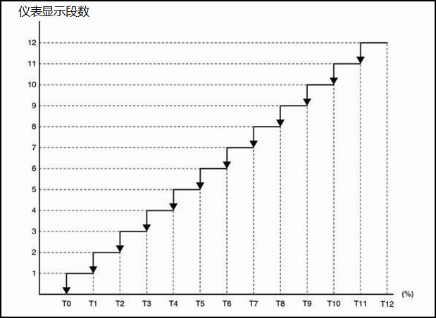
Power battery temperature meter display/go-out segment
![]()
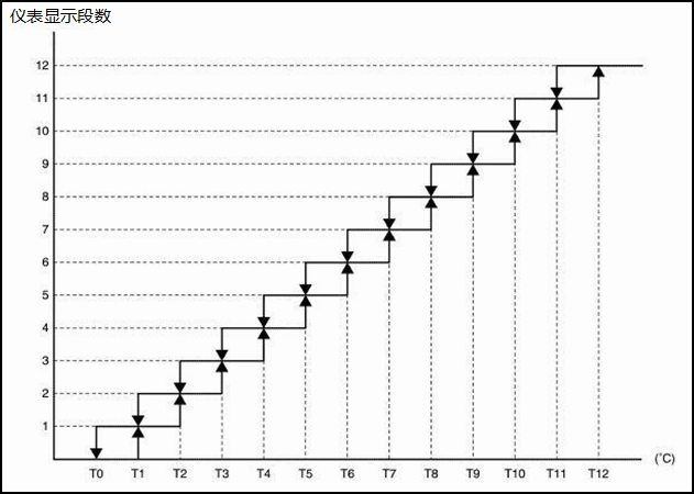
Relation between battery temperature meter display segment and battery temperature
|
Display segment |
Temperature(°C) |
- |
|
12 |
60 |
T12 |
|
11 |
57.5 |
T11 |
|
10 |
55 |
T10 |
|
9 |
52.5 |
T9 |
|
8 |
50 |
T8 |
|
7 |
36.8 |
T7 |
|
6 |
23.5 |
T6 |
|
5 |
10.3 |
T5 |
|
4 |
-3 |
T4 |
|
3 |
-6 |
T3 |
|
2 |
-9 |
T2 |
|
1 |
-12 |
T1 |
|
0 |
-15 |
T0 |
Reminder:
Battery temperature displayed on battery temperature meter varies according to power battery available capacity.
Power battery available capacity meter
Power battery available capacity meter system description
CAN communication Battery health state signal Battery health state signal Battery controller Electrical instrument CAN communication Vehicle controller
Description
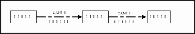
● Battery controller transmits battery available capacity signal to vehicle controller through CAN communication. After dealing with the signal, vehicle controller transmits battery available capacity signal to electrical instrument through CAN signal. Electrical instrument displays battery temperature information on battery temperature meter.
● Electrical instrument displays battery available capacity information on battery available capacity meter.
Reminder:
When power battery decays, its energy decreases.
Signal path
|
Signal name |
Signal path |
|
Battery controller (battery available capacity signal)→Vehicle controller→Electrical instrument |
Display bar parameter comparison table
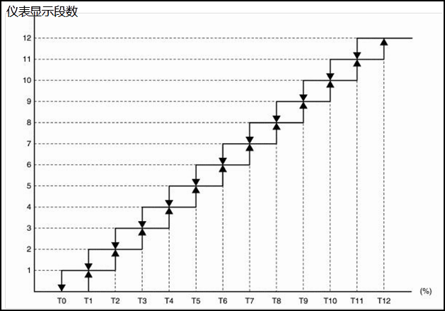
Battery available capacity meter display
![]()
Relation between battery available capacity meter display and battery available capacity:
|
Display segment |
Battery available capacity (%) |
- |
|
12 |
Over 85 |
T12 |
|
11 |
85 |
T11 |
|
10 |
78.75 |
T10 |
|
9 |
72.5 |
T9 |
|
8 |
66.25 |
T8 |
|
7 |
60 |
T7 |
|
6 |
53.75 |
T6 |
|
5 |
47.5 |
T5 |
|
4 |
41.25 |
T4 |
|
3 |
35 |
T3 |
|
2 |
28.75 |
T2 |
|
1 |
22.5 |
T1 |
|
0 |
16.25 |
T0 |
Power battery capacity meter system description
System schematic diagram
Battery level signal Battery level signal CAN communication Electrical instrument CAN communication Battery controller Vehicle controller
● Battery controller transmits battery capacity signal to vehicle controller through CAN communication. After dealing with the signal, vehicle controller transmits battery capacity signal to electrical instrument through CAN signal. Electrical instrument displays battery capacity information on battery capacity meter.
● Power battery capacity value is displayed on battery capacity meter.
Reminder:
l Power battery available capacity is displayed in percentage of full battery capacity.
l When power battery temperature changes, power battery volume may change. Thus, power battery available capacity may change.
Signal path
|
Signal name |
Signal path |
|
Battery capacity signal |
Battery controller (battery capacity signal)→Vehicle controller→Electrical instrument |
Display bar parameter comparison table
Battery meter display
![]()
Relation between battery meter display segment and battery capacity:
|
Display segment |
Battery capacity(%) |
- |
|
12 |
96 |
T12 |
|
11 |
88 |
T11 |
|
10 |
80 |
T10 |
|
9 |
72 |
T9 |
|
8 |
64 |
T8 |
|
7 |
56 |
T7 |
|
6 |
48 |
T6 |
|
5 |
40 |
T5 |
|
4 |
32 |
T4 |
|
3 |
24 |
T3 |
|
2 |
16 |
T2 |
|
1 |
8 |
T1 |
|
0 |
0 |
T0 |
Indicator lamp and warning lamp
Indicator lamp and warning lamp system description
System schematic diagram
Electrical instrument input signal (CAN communication)
|
Transmitting component |
Signal name |
|
ABS controller |
ABS malfunction warning lamp signal |
|
Vehicle controller |
Electric motor malfunction warning lamp signal |
|
Battery malfunction warning lamp signal |
|
|
System malfunction warning lamp signal |
|
|
Limit power indicator lamp signal |
|
|
High voltage cut-off indicator lamp signal |
|
|
READY indicator lamp signal |
|
|
Charging wire connection indicator lamp signal |
|
|
Charging status indicator lamp signal |
Electrical instrument output signal (CAN communication)
|
Receiving component |
Signal name |
|
Vehicle controller |
Total mileage signal |
Description
The illumination and go-off of red indicator lamp and yellow indicator lamp are displayed on electrical instrument.
The red indicator lamp displayed on electrical instrument is listed as following:
- Trunk indicator lamp
- Door open indicator lamp
- Safety belt warning lamp
- Airbag warning lamp
- Electronic power steering indicator lamp
- Hand brake indicator lamp
- Electric motor malfunction warning lamp
- Battery malfunction warning lamp
- System malfunction warning lamp
- Charging wire connection indicator lamp
The yellow indicator lamp displayed on electrical instrument is listed as following:
- Rear fog lamp indicator lamp
- Front fog lamp indicator lamp
- VSP indicator lamp VSP
- ABS malfunction warning lamp
- Limit power indicator lamp
- High voltage cut-off indicator lamp
- Charging status indicator lamp
Electrical instrument illumination control
Electrical instrument system description
System schematic diagram
 Description
Control instrument illumination based on following signals
- Position lamp switch
- Backlight lamp adjustment signal
Based on following conditions, electrical illumination can be divided into night mode and day mode.
|
Condition |
Instrument illumination |
||
|
Instrument illumination switch |
Position lamp switch |
||
|
Low beam lever |
Outside: bright* |
Day mode |
|
|
Inside: dark* |
Night mode |
||
|
OFF |
Day mode* |
Day mode |
|
The operation of light control knob can adjust display brightness of electrical instrument.
|
Signal name |
Signal path |
|
Instrument illumination switch signal |
Instrument illumination switch (illumination signal)→Electrical instrument |
Electrical instrument display effect function
Electrical instrument display effect function system description
System schematic diagram
 Description
Boot display effect
When turning key to “ON” position, the start of electrical instrument has following effect:
● Battery available capacity meter
Electrical instrument “ON” position display effect
Electric instrument control logic at ON gear as following:
|
Control content |
Control logic |
|
Power meter |
Display effect shows as following sequence: 1 Display bar becomes bright step by step, until whole line bright 2 Display bar goes off step by step, until whole line goes off 3 Display fully goes off. Display respective value according the current received data. |
|
Battery available capacity meter |
|
|
Battery meter |
|
|
Battery temperature meter |
Reminder:
If the key is turned from “ON” position to “LOCK” position or “ACC” position during starting up, display effect will stop accordingly.
Information display system description
System schematic diagram
Electric motor rotation speed signal Energy flow
signal Average energy consumption signal Gear signal CAN communication Electrical instrument Vehicle controller Electric motor controller CAN communication
![]()
Electrical instrument input signal (CAN communication)
|
Signal source |
Signal name |
|
Gear information signal |
|
|
Average energy consumption signal |
|
|
Energy flow signal |
|
|
Electric motor controller |
Electric motor rotation speed signal |
Description
Liquid crystal display on electrical instrument displays vehicle information.
Display information signal comes from vehicle controller and electric motor controller.
Based on received signal, electrical instrument liquid crystal display shows following information:
- Gear display
- Average consumption display
- TRIP mileage display
- Total mileage display
Information display screen is divided into A, B, C sections. Each section shows different content according to the necessity of display content. There is also section combination.
|
Display section |
Display content |
|
|
A |
Speed display |
|
|
B |
Energy flow display |
|
|
Warning tip display |
||
|
C |
Gear |
|
|
TRIP mileage |
||
|
Total mileage |
||
|
A+B |
Door open display |
|
|
B+C |
Charging information display |

Charging time display
Based on following signal, electrical instrument displays charging time.
|
Vehicle controller (reminder charging time signal) |
Tip reminder
Electrical instrument produces break-off, and shows respective warning, reminder and maintenance tips according to relevant component or switch signal.
When break-off condition is satisfied, generally displayed information will be shifted to warning information.
|
Displayed tip |
|
|
Mode type |
Display limit power mode warning |
|
Status type |
Display power battery temperature extreme high warning |
|
Display power battery temperature extreme low warning |
|
|
Display charging completed warning |
|
|
Display charging wire connection warning |
|
|
Display release hand brake warning |
|
|
Display press brake pedal warning |
|
|
Display door open warning |
|
|
Warning type |
Display go to 4S showroom for maintenance warning |
|
Display gear shift warning |
|
|
Display driver warning |
|
|
Display vehicle malfunction and pullover warning |
Limit power mode warning
When power battery level is low or the vehicle is under limit power mode, limit power mode is displayed.
Electrical instrument displays or does not display “limit power mode” according to following signal.
|
Signal name |
Signal path |
|
Limit power mode signal |
Vehicle controller (CAN signal)→Electrical instrument |
Power battery temperature extreme high warning
When power battery temperature is extremely high, “battery temperature extreme high” is displayed.
|
Signal name |
Signal path |
|
Vehicle controller (CAN signal)→Electrical instrument |
Power battery temperature extreme low warning
When power battery temperature is extremely low, “battery temperature extreme low” is displayed.
|
Signal name |
Signal path |
|
Power battery temperature extreme low signal |
Vehicle controller (CAN signal)→Electrical instrument |
Charging completed warning
When power battery charging is completed, “charging is completed” is displayed.
|
Signal name |
Signal path |
|
Vehicle controller (CAN signal)→Electrical instrument |
Charging wire connection warning
When power battery charging wire is connected, please start the vehicle and turn the key to “ON” position. “Charging wire is connected” is displayed.
|
Signal name |
Signal path |
|
Power battery charging wire connection signal |
Vehicle controller (CAN signal)→Electrical instrument |
When it is necessary to remind customer to release hand brake, “Release hand brake” is displayed.
|
Signal name |
Signal path |
|
Release hand brake warning signal |
Vehicle controller (CAN signal)→Electrical instrument |
When it is necessary to remind customer to press brake pedal, “Press brake pedal” is displayed.
|
Signal name |
Signal path |
|
Press brake pedal warning signal |
Vehicle controller (CAN signal)→Electrical instrument |
When any door opens or trunk opens, door open image is displayed.
|
Signal name |
Signal path |
|
Door open signal |
Door contact switch→Electrical instrument |
Go to 4S showroom for maintenance warning
When the vehicle needs go to JAC distributor for maintenance, “Go to 4S showroom for maintenance” is displayed.
|
Signal name |
Signal path |
|
Maintenance warning signal |
Vehicle controller (CAN signal) |
When the vehicle needs travelling and gear shift lever is not at “N” position, “Turn back to “N” position and then “READY” is displayed.
|
Signal name |
Signal path |
|
Gear shift warning signal |
Vehicle controller (CAN signal) |
When the vehicle is under potential safety risk and it is necessary to remind the driver, “Vehicle-in-danger, vehicle pull-over, trouble lamp, leave immediately” or “Vehicle failure, vehicle pull-over” is displayed.
|
Signal name |
Signal path |
|
Driver warning signal |
Operation
|
SN |
Switch name |
Operation |
Description |
|
1 |
Illumination control |
Finger press |
Pull roller upward or downward to adjust instrument backlight. |
|
2 |
TRIP |
Press TRIP switch for 3 seconds to reset TRIP mileage. |
|
|
3 |
ECO |
At “D’ gear, press ECO switch. Gear shows “ECO”, and the vehicle enters economy mode. |
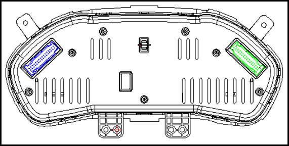
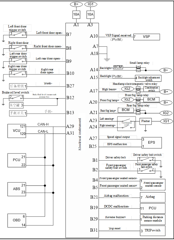
Connector layout

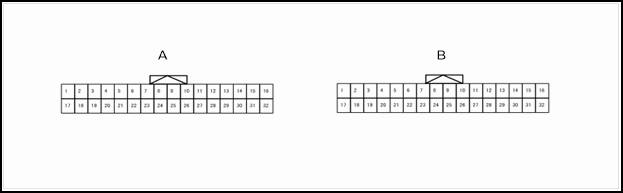
Instrument connector terminal definition
|
Pin number |
Description |
Condition |
Value |
||
|
+ |
- |
Signal name |
Input/output |
||
|
A1 |
GND |
Constant power supply |
Input |
KEY ON |
12V battery voltage |
|
A3 |
GND |
Ignition electric source |
Input |
KEY ON |
12V battery voltage |
|
A7 |
GND |
GND |
Input |
KEY ON |
0V |
|
A10 |
GND |
Receive VSP signal |
Input |
KEY ON |
PWM signal |
|
A14 |
GND |
Position lamp |
Input |
KEY ON |
12V |
|
A14 |
GND |
Backlight lamp control signal |
Input |
KEY ON |
PWM signal |
|
A17 |
GND |
High beam 1 |
Input |
KEY ON |
0V |
|
A18 |
GND |
High beam 2 |
Input |
KEY ON |
12V |
|
A20 |
GND |
Front fog lamp indicator lamp |
Input |
KEY ON |
12V |
|
A21 |
GND |
Rear fog lamp indicator lamp |
Input |
KEY ON |
12V |
|
A23 |
GND |
Left steering indicator lamp |
Input |
KEY ON |
12V |
|
A24 |
GND |
Right steering indicator lamp |
Input |
KEY ON |
12V |
|
A27 |
GND |
Speed signal |
Output |
KEY ON |
PWM signal |
|
A29 |
GND |
CANL |
- |
KEY ON |
- |
|
A31 |
GND |
CANH |
- |
KEY ON |
- |
|
B1 |
GND |
Main safety belt indicator lamp |
Input |
KEY ON |
0V |
|
B2 |
GND |
Sub safety belt indicator lamp |
Input |
KEY ON |
0V |
|
B4 |
GND |
Pilot seat sensor + |
Input |
KEY ON |
0V |
|
B5 |
GND |
Pilot seat sensor - |
Input |
KEY ON |
PWM signal |
|
B7 |
GND |
Left front door open signal |
Input |
KEY ON |
0V |
|
B8 |
GND |
Right front door open signal |
Input |
KEY ON |
0V |
|
B9 |
GND |
Left rear door open signal |
Input |
KEY ON |
0V |
|
B8 |
GND |
Right rear door open signal |
Input |
KEY ON |
12V/悬空 |
|
B12 |
GND |
Low brake level |
Input |
KEY ON |
0V |
|
B13 |
GND |
Hand brake signal |
Input |
KEY ON |
0V |
|
B19 |
GND |
Charging and discharging indication |
Input |
KEY ON |
0V |
|
B21 |
GND |
Airbag warning lamp |
Input |
KEY ON |
0V |
|
B25 |
GND |
Low beam indicator lamp |
Input |
KEY ON |
0V |
|
B27 |
GND |
Trunk indicator lamp |
Input |
KEY ON |
0V |
|
B29 |
GND |
Reverse buzzer signal |
Input |
KEY ON |
PWM signal |
|
B31 |
GND |
TRIP reset signal |
Input |
KEY ON |
PWM signal |
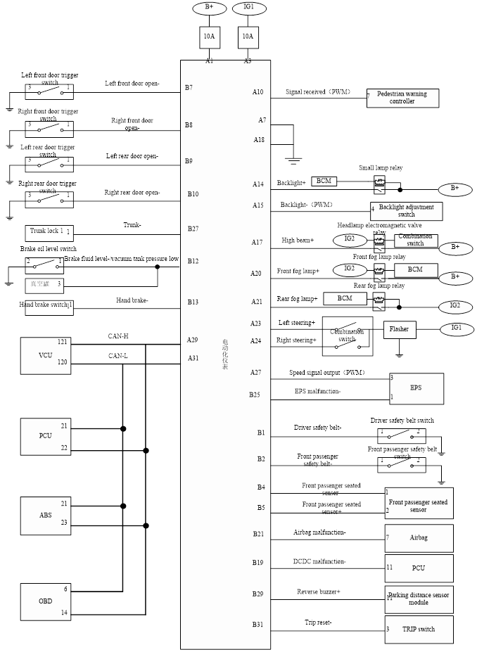
Electrical instrument electrical schematics
Electrical instrument electrical schematic diagram
Electrical Instrument-
1. Check fuse
Check whether following fuses are burned out.
|
Power supply |
Fuse number |
|
12V battery |
Self-contained fuse (outside fuse box) |
|
ON position signal |
IG1 fuse IG1 (outside fuse box) |
Check whether the result is normal?
Check electric potential difference between electric instrument harness terminal connector and ground wire.
|
Key position |
Magnitude of voltage |
|||
|
ICM |
||||
|
Terminal number |
||||
|
M26 |
1 |
LOCK |
12V battery voltage |
|
|
3 |
ON |
|||
Check whether the result is normal?
No >> Check the harness between electrical instrument and fuse.
3. Check grounding circuit
1. Turn the key to “LOCK” position or pull out the key.
2. Disconnect electrical instrument connector.
3. Check the connectivity between electric instrument harness terminal connector and ground wire.
|
ICM |
|||
|
Connector |
|||
|
M26 |
7 |
Ground |
|
Check whether the result is normal?
No >> Repair harness or connector.
Instrument control switch circuit
1.Check electrical instrument input signal
1. Turn the key to “ON” position.
2. Check the voltage between following terminals and electrical instrument.
|
Electrical Instrument- |
Condition |
Voltage |
||
|
Port number |
||||
|
M36 |
31 |
Ground地 |
Press “TRIP” switch. |
0V |
|
Except above situation. |
12V |
|||
|
M26 |
14 |
15 |
Rotate dimmer knob to maximum value. |
12V |
|
Rotate dimmer knob to maximum value |
0V |
|||
Check whether the result is normal?
2. Check instrument control switch circuit
1. Turn the key to “LOCK” position or pull out the key;
2. Disconnect instrument control switch connector and electrical instrument connector;
3. Check the connectivity between electric instrument harness terminal connector and instrument control switch harness terminal.
|
Multimeter positive pole |
Multimeter negative pole |
Connectivity |
||
|
ICM |
“TRIP” switch |
|||
|
Terminal number |
Connector |
Terminal number |
||
|
M36 |
31 |
M33 |
3 |
Conduction |
|
Multimeter positive pole |
Multimeter negative pole |
Connectivity |
||
|
ICM |
Dimming switch |
|||
|
Connector |
Terminal number |
Connector |
Terminal number |
|
|
M26 |
15 |
M32 |
4 |
Conduction |
|
Multimeter positive pole |
Multimeter negative pole |
Connectivity |
||
|
VCU |
“ECO” Switch |
|||
|
Connector |
Terminal number |
Connector |
Terminal number |
|
|
F21 |
40 |
M34 |
3 |
Conduction |
4. Check the connectivity between electric instrument harness terminal connector and instrument control switch harness terminal.
|
Multimeter positive pole |
Multimeter negative pole |
Connectivity |
|
|
ICM |
|||
|
Connector |
Terminal number |
||
|
M26 |
7 |
Ground |
Conduction |
Check whether the result is normal?
Yes >> Checking is finished.
No >> Repair harness or connector.
Electrical Instrument-
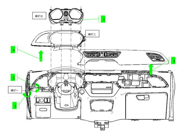
Demolition
1. Remove the left lower guard plate.
Lift up the guard plate through the dismantling hole of the left lower guard plate and remove the 1 screw inside.
2、Disassemble the lower guard plate
3、Remove the dashboard light strips
Lift the dashboard light strip and pull it out
4、Remove the instrument lower guard
Remove the fixing screw of the instrument panel and pull out the shield
5, remove the instrument cluster
Remove the four mounting screws from the meter, pull the meter out, and unplug the connector.
installation
Assemble in the reverse order of removal.
Control switch
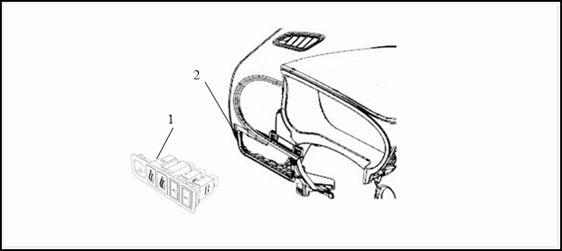
1 Control switch assembly 2 Dashboard
Removal
1 Remove control switch assembly;
2 Remove connector;
3 Remove control switch.。
Installation
Please follow the reversed sequence of removal to install.