Precautions of electric technician who use Medical Electronic Equipment
Inspection of key points before the maintenance
Precautions of auxiliary restraint system "airbag" and "seat belt pretension"
Precautions of removing the 12V battery
Safety Precaution
Precautions of electric technician who use Medical Electronic Equipment
Warning:
● Strong magnetic components have been assembled on this vehicle.
● Technicians shouldn't operate electronic pacemaker or other medical electronic devices in this vehicle, or the functions of medical devices may be affected by strong magnetic components.
Precautions for normal charging
Warning:
●
If a technician uses a medical electric device
such as an implantable cardiac pacemaker or a
heart pacemaker/defibrillator, the effects of the devices must be checked
before starting the charge operation.
●
If a technician using a medical electric device
such as implantable cardiac
pacemaker or an implantable heart pacemaker defibrillator .he must not enter
the vehicle compartment (including luggage room) during normal charge
operation.
Communication equipment operation precautions
● If the technician uses medical electronic devices such as cardiac pacemaker, cardioverter or defibrillator and other medical electronic equipment, please keep enough distance with the communication devices.
● The electromagnetic wave of the remote intelligent terminal may affect the function of the medical device such as cardiac pacemaker, cardioverter, defibrillator and other medical electronic devices.
● If the technician uses the medical device such as cardiac pacemaker, multiplexer, defibrillator and other medical electronic equipment, the electromagnetic wave of the remote intelligent terminal may affect the function of the device. The possible effect of the remote intelligent terminal on the medical electronic devices must be checked by the manufactures of the medical electronic devices .
Inspection of key points before the maintenance
The high-voltage system may automatically operate. Please confirm the remote air conditioning and fixed-time charging haven’t been set before the maintenance.
Attention:
If remote air-conditioning or fixed-time charging is set, the high voltage system will run automatically even the switch is off.
Precautions of auxiliary restraint system "airbag" and "seat belt pretension"
The
Supplemental Restraint System such as “AIR BAG” and “SEAT BELT PRE-TENSIONER”,
used along
with a front seat belt, helps to reduce the risk or severity of injury to the
driver and front passenger for certain types of collision. This system includes
seat belt switch inputs and dual front air bags. Information necessary to
service the system safely is included in the “SRS AIR BAG” and “SEAT BELT” of
this Service Manual.
Warning:
● To avoid rendering the SRS inoperative, which could increase the risk of personal injury or death in the event of a collision that would result in air bag inflation, all maintenance must be performed by an authorized JAC dealer.
●
Improper maintenance, including incorrect
removal and installation of the SRS, can lead to personal
injury caused by unintentional activation of the system. For removal of Spiral
Cable and Air Bag Module, see “SRS AIR BAG”.
● Do not use any electrical test devices to test any circuit of the auxiliary restraint system unless these tests are in the instructions described in the service manual. The wire harness and connectors of the auxiliary restraint system should adopt to yellow or orange color.
Precautions when using power tools(pneumatic or electric) and hammer
●
When working near the Air Bag Diagnosis Sensor Unit or other Air
Bag System sensors with the power switch ON, never use air or electric power
tools or strike near the sensor(s) with a hammer. Heavy vibration could
activate the sensor(s) and deploy the air bag(s), possibly causing serious
injury.
● When using power tools or a hammer, turn the key in the "LOCK" position, unplug the cathode of 12V lead-acid battery and wait at least 1 minute for maintenance.
Precautions of removing the 12V battery
When removing the 12V battery, turn the power switch to “ON”, and then to “OFF”.
Note:
● The automatic 12V battery charge function may start even when the power switch is in “LOCK”state.
● The automatic 12V battery charge control does not start within approximately one hour when the power switch is turned ON/OFF.
● Before the repairing which no need the power: rotate the key to LOCK gear and disconnect the 12V battery negative.
● After disconnect the 12V battery negative, the memory of radio and other control devices will be cleared.
● Replace new oil seal, gasket,gasket ring,O-type ring,lock washer,cotter pins,self-locking nuts and other parts.
● Place the removed parts in order and according to the positions as they are assembled .
● If necessary, use approved binders, sealants or equivalent products.
● For safe and efficient repair work, you should use hand tools, power tools (disassembly only) and special tools.
● Before repairing the vehicle:
Cover the fender, interior and carpet with a suitable cover. Be careful do not scratch the paintwork with keys, buttons or something like this.
Disassembly and Assembly
Interior rear view mirror
Disassembly
Disassemble rear view mirror from the base with slotted screwdriver.
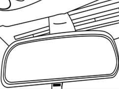
Installation
Press inner rear view mirror into the inner rear view mirror pedestal and confirm the installation is firm.
Install the inner rear view mirror base.
Precautions:
● The inner rear view mirror is attached to the rear view mirror base. The inner rear view mirror pedestal is glued to the windshield with Plastic polyethylene acetal adhesive. To install an independent inner rear view mirror pedestal or a new part, the following items are required:
● Loctite™ Instant Adhesive 312.
● (according to preparation of step 4 and 5 )Original inner rear view mirror pedestal or replace new inner rear view mirror pedestal.
● A wax marker pen or crayon.
● Isopropyl alcohol.
● Cleaning tissue
● Thin steel gauze or sandpaper (320 or 360)
● Measure the top dimensions from the top of windshield (1) to the inner rear view mirror pedestal(2). The size is 79 mm.
● Mark at a position outside of the windshield with a wax pen or crayon. Draw a large circle along the inner rear view mirror pedestal outside edge on the windshield outer surface (3).

 |
The sketch map of installation of the inner rear view mirror
● Use glass detergent of common type,clean the circle on the inner side of windshield with polishing paper towel or common part number. Scrub the area until it is completely clean and dry. After drying, clean the area with the tissue what stained with isopropyl alcohol to remove the traces of washing powder or detergent.
● Attention:
● If the original inner rear mirror pedestal is used again, all adhesive traces must be removed before reinstalling.
● Use a thin (320 or 360) steel gauze or sandpaper to polish the bonding surface of the new inner rear view mirror or factory mounted original inner rear view mirror pedestal.
● Wipe the polished inner rear mirror pedestal with a clean tissue stained with isopropyl alcohol. open-air dry it.
● Before install it onto the windshield, prepare the inner rear mirror pedestal according to the manufacturer's instructions.
● Place the inner rear view mirror correctly at the pre-marked position. The half rounded end pointing upward is not allowed. Press the inner rear view mirror pedestal against the windshield for 30 to 60 seconds, applying constant pressure on the windshield.
● After 5 minutes, remove all excess adhesive with tissue stained with isopropyl alcohol or window cleaner.
● Re-install the inner rear view mirror.
Exterior rear view mirror
Disassembly

![]()

● Disconnect the battery negative.
● Carefully pry the trim panel with a slotted screwdriver.
● Unscrew the 3 fixing bolts of rear view mirror.
● Disconnect the rear view mirror connector.
● Remove the rear view mirror assembly
Installation
Follow the opposite sequence of the disassembly to asseemble.