Post the Warning Label of "HIGH VOLTAGE COMPONENTS IN REPARING DO NOT TOUCH"..... 28
DIAGNOSTIC TOOL CHECKING SYSTEM FOR NEW ENEERGY VEHICLE........................................ 54
HOW TO USE THIS MANUAL
This volume explains “Removal Disassembly Installation Inspection and Adjustment” and “Trouble Diagnoses”.
|
|
Description |
|
DANGER |
Violation operation may cause a death or serious personal injury. Example Touching high voltage components without using the appropriate insulated protective equipment |
|
WARNING |
Violation operation may cause a death or serious personal injury. |
|
CAUTION |
Violation operation may cause a serious personal injury or damage of components. |
|
NOTE |
Provide helpful information |
|
OTHERS |
Provide helpful information |
|
Symbol |
Description |
|
|
Violation operation may cause an electric shock. |
|
|
Please wear insulated gloves when checking or performing service operation of high voltage components. |
|
|
Please wear insulated gloves when checking or performing service operation of high voltage components on lift-up vehicles. |
|
|
Always wear under the following circumstances During removal/installation or check operation of high voltage components or harness where spark might appear by short circuit. Service operation inside battery pack. |
|
|
Always use when performing high voltage components such as operation inside battery pack. |
 Electric
shock symbol
Electric
shock symbol  Insulated
gloves
Insulated
gloves  Insulated
safety shoes
Insulated
safety shoes  Safety
glasses
Safety
glasses  Insulated
tools
Insulated
tools The UNITS given in this manual are primarily expressed as the SI UNIT (International System of Unit).And with regard to tightening torque of bolts and nuts please refer to Standard Tightening Torque Table.
“Example ”
Range
Fixing bolts of power train and suspension 50-70 N·m
l The contents are listed on the first page of every chapter.
l The small illustrations show the important steps such as inspection use of special tools knacks of work and hidden or tricky steps which are not shown in the previous large illustrations.
l Assembly inspection and adjustment procedures for the complicated units are presented in a step-by-step format where necessary.
Relation between Illustrations and Descriptions
The following sample explains the relation between the part description part name and service procedures.

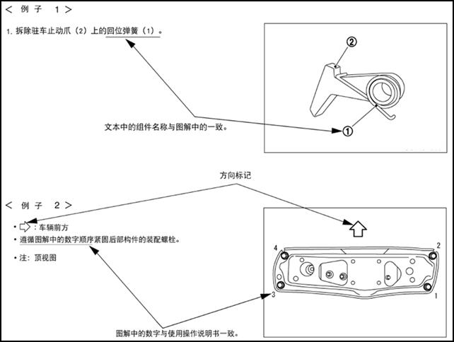
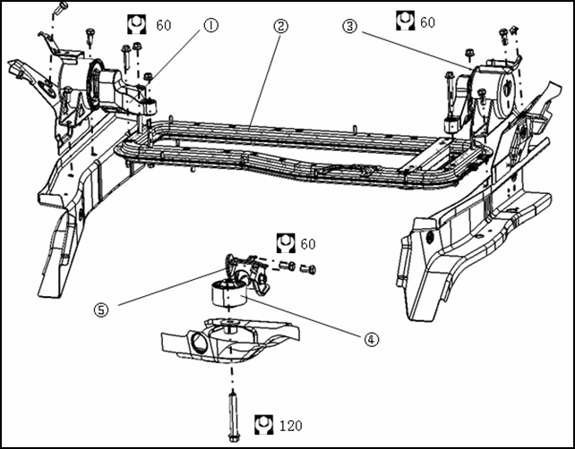
Components
The large illustrations are exploded views (see the following) and contain components standard parts tightening torques lubrication points assembly method and other information necessary to repairs.
Components shown in an illustration may be identified by a circled number.When this style of illustration is used the text description will follow the illustration.
|
1 left suspension cushion |
2 power train support beam |
3 right suspension cushion |
|
4 rear suspension bracket |
5 rear suspension cushion |
|
HOW TO FOLLOW TROUBLE DIAGNOSES
Trouble diagnoses indicate work procedures required to diagnose problems effectively.Observe the following instructions before diagnosing.
l Before performing trouble diagnoses read the “work flow” in each section.
l After repairs re-check that the problem has been completely eliminated.
l Refer to Components Parts and Harness Connector Location for the Systems described in each section for identification/location of components and harness connectors.
l When checking circuit continuity ignition switch should be OFF.
l Please refer to the Circuit Diagram for quick pinpoint check.If you need to check circuit continuity between harness connectors in more detail such as when a sub-harness is used refer to Wiring Diagram in each individual section and Harness Layout in “Grounding and Loop” section for identification of harness connectors.
l Before checking voltage at connectors check 12V battery voltage.
l After accomplishing the Diagnosis Procedures and Electrical Components Inspection check that all harness connectors are reconnected as they were.
How to Follow Test Steps in Trouble Diagnosis

1 Test group number and test group title
Test group number and test group title are shown in the upper portion of each test group.
2 Work and diagnosis procedure
Start to test according to procedures in every test group.
3 Questions and results
Questions and results are listed in each test group.
4 Action
Next test action is based on test results of each group.
HOW TO READ WIRING DIAGRAMS
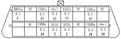
Connector SymbolsConnector symbols are shown from the terminal side and the harness side.See the following picture l Terminal side diagram shows the view from front of the connector and marked as TS.TS l Harness side diagram shows the view from rear of the connector and marked as HS.HS l Most of connector symbols in wiring diagram are shown from the terminal side. |
|
|
Male and female terminals Connector guides for male terminals are shown in black and female terminals in white in wiring diagrams. Example |
|
|
|
|


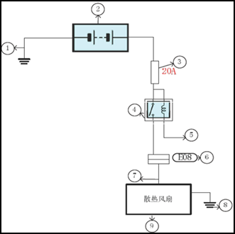
fan
Description
|
Number |
Item |
Description |
|
1 |
Battery ground |
Vehicle battery ground |
|
2 |
Battery |
12V battery 12V |
|
3 |
Fuse |
Fuse and its available current value |
|
4 |
Relay |
Internal controlling principle of relay |
|
5 |
Relay control |
Working condition of relay |
|
6 |
Connector number |
Alphabetic characters show to which harness the connector is placed Numbers show the connector number |
|
7 |
Power supply |
Show the power supply of appliance |
|
8 |
Ground |
Show the ground location of appliance |
|
9 |
Component |
Show the name of appliance |
|
Switch positions shown in wiring diagrams are when the vehicle is in the “normal” condition. A vehicle is in the “normal” condition when l Key is in “LOCK”. l Doors hood and trunk are closed. l Pedals are not stepped. l Parking brake is released. |
Normally
closed Normally
open |

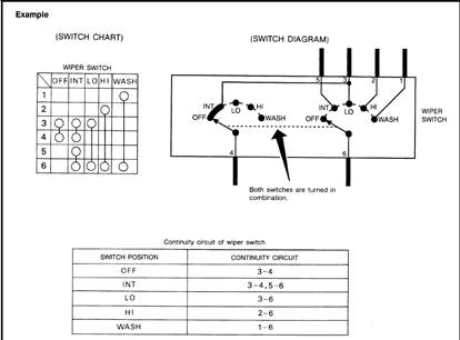
The continuity of multiple switch is described in two ways as shown below.
l The switch chart is used in schematic diagrams.
l The switch diagram is used in wiring diagrams.
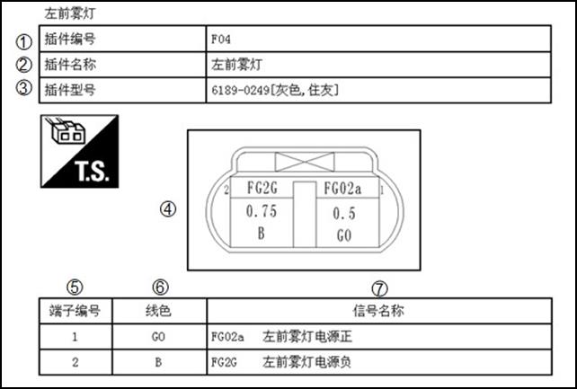
Terminal
No. Color
of Wire Signal
Name Negative
pole of left front fog light Left
front fog light Connector
No. Connector
Name Left
font fog light Connector
Type [grey
Sumitomo]
Description
|
Number |
Item |
Description |
|
1 |
Connector number |
Alphabetic characters show to which harness the connector is placed Numbers show the connector number |
|
2 |
Connector name |
Definition of connector name |
|
3 |
Connector type |
Connector property |
|
4 |
Connector |
Projection of connector outline |
|
5 |
Terminal number |
Information of connector terminal (see 1 and 2 in the picture) |
|
6 |
Wire color |
Wire color code |
|
B=black W = white R = red G = green L = blue Y = yellow LG light green = BG = beige BR = brown OR or O = orange P = pink PU or V (Violet) = purple GY or GR = grey |
||
|
When the wire color is striped the base color is give first followed by the stripe color example B\W= black with white stripe |
||
|
7 |
Signal name |
Show the physical meaning of signal |
Wrap of wiring
|
No. |
Symbol |
Meaning |
|
1 |
|
Wrap with black corrugated pipe |
|
2 |
|
Wrap with black clot tape |
|
3 |
|
Tightly wrap with black PVC tape |
|
4 |
|
Wrap with black cloth |
ABBREVIATIONS
|
Abbreviation |
Name |
|
A/C |
Air conditioner system |
|
AC |
Air conditioner controller |
|
BDU |
Battery cut-off unit |
|
CHR |
Off-board charger |
|
DTC |
Diagnostic trouble code |
|
DC/DC |
Direct current converter |
|
DEF |
Defrost |
|
E-Drive |
Electric- drive |
|
EC |
AC compressor controller |
|
HVAC |
Main device of air conditioner |
|
ICM |
Combination instrument |
|
LBC |
Battery controller |
|
OBD |
On board diagnositics |
|
PCU |
Motor controller |
|
T-BOX |
Remote intelligent terminal |
|
TM |
Reducer |
|
VIN |
Vehicle identification number |
|
VCU |
Vehicle control unit |
TIGHTENING TORQUE OF STANDARD BOLTS AND SCREWS
|
Size |
||||||
|
4.8(4) |
8.8(8) |
10.9(10) |
||||
|
Tightening torque (N.m) |
||||||
|
1 |
1~1.5 |
2~3 |
3~3.8 |
|
||
|
2 |
2~3 |
4~7 |
6~8 |
|
||
|
3 |
3~6 |
7~11 |
10~13 |
|
||
|
4 |
6~8 |
12~16 |
17~22 |
|
||
|
5 |
8~11 |
18~32 |
25~35 |
|
||
|
6 |
M8×1 |
6~12 |
20~34 |
27~38 |
|
|
|
7 |
17~22 |
36~55 |
50~63 |
|
||
|
8 |
M10×1.25 |
18~24 |
40~70 |
63~80 |
|
|
|
9 |
M10×1 |
20~25 |
42~72 |
65~88 |
|
|
|
10 |
30~39 |
62~78 |
87~109 |
|
||
|
11 |
M12×1.5 |
32~41 |
65~81 |
91~114 |
|
|
|
12 |
M12×1.25 |
34~42 |
68~85 |
95~119 |
|
|
|
13 |
M12×1 |
35~44 |
70~88 |
99~125 |
|
|
|
14 |
45~60 |
99~124 |
140~175 |
|
||
|
15 |
M14×1.5 |
53~67 |
107~134 |
150~188 |
|
|
|
16 |
M14×1.25 |
56~69 |
111~139 |
156~195 |
|
|
|
17 |
M14×1 |
58~72 |
115~144 |
162~202 |
|
|
Screw tightening torque table
|
Tightening torque (N.m) |
|||||
|
|
|||||
|
M4 |
1~1.5 |
1.5~2.5 |
|
||
|
M5 |
2~3 |
3.5~5.5 |
|
||
|
M6 |
3~4 |
6~9 |
|
||
|
M8 |
8~11 |
16~22 |
|
||
|
M10 |
13~22 |
25~30 |
|
||
Tightening Torque of Key Parts
|
No. |
Name |
Tightening torque (N•m) |
|
1 |
Fixing bolts of gear shifting operating mechanism |
30~35 |
|
2 |
Self-lock nut of drive shaft |
240~260 |
|
3 |
Fixing bolts between rear suspension cushion and sub-frame |
130±10 |
|
4 |
Connecting bolts between rear suspension bracket and reducer |
60±10 |
|
5 |
Connecting bolts between rear suspension bracket and its cushion |
100±10 |
|
6 |
Connecting bolts between left suspension cushion and left carling |
60±10 |
|
7 |
Connecting bolts(nuts) between left suspension bracket and power train beam |
55±5 |
|
8 |
Connecting bolts(nuts) between right suspension bracket and power train beam |
55±5 |
|
9 |
Connecting bolts between right suspension cushion and right carling |
60±10 |
|
10 |
Fixing bolts of electric accelerating pedal |
7~11 |
|
11 |
Fixing bolts between steering gear and sub-frame |
95~105 |
|
12 |
Connecting bolts between steering gear rod ball pin and steering knuckle |
40~50 |
|
13 |
Lock nut of inside bar length adjustment |
45~55 |
|
14 |
Connecting bolts between steering column and steering shaft with cardan joint |
30~35 |
|
15 |
Connecting bolts between steering shaft with cardan joint and steering gear |
30~35 |
|
16 |
Nut of steering disc and steering column |
42~52 |
|
17 |
Fixing nuts of brake pedal floor and vacuum booster |
20~25 |
|
18 |
Fixing bolts between brake pedal upper and instrument frame |
20~25 |
|
19 |
Connecting bolts of ABS hydraulic regulator and brake pipe connector ABS |
16~18 |
|
20 |
Assembly of brake pipes |
M6 bolt 10~15 M8 bolt 20~25 |
|
21 |
Fixing bolts of brake caliper |
65~75 |
|
22 |
Fixing bolts between brake handle and vehicle floor |
20~25 |
|
23 |
Fixing bolts/nuts between front column and steering knuckle / |
110~130 |
|
24 |
Fixing bolts(assembly in X direction) between lower suspension arm and sub-frame |
130~150 |
|
25 |
Fixing bolts between stabilizer and sub-frame |
60~72 |
|
26 |
Fixing nuts between stabilizer and stabilizer pull rod |
2~3 |
|
27 |
Fixing nuts between stabilizer pull rod and lower suspension arm |
2~3 |
|
28 |
Fixing nuts between lower suspension arm ball pin and steering knuckle |
60~72 |
|
29 |
Fixing nuts between front column and vehicle body |
50~70 |
|
30 |
Mounting bolts (front) between sub-frame and vehicle body |
110~130 |
|
31 |
Mounting bolts (middle) between sub-frame and vehicle body |
130~150 |
|
32 |
Mounting bolts (rear) between sub-frame and vehicle body |
60~72 |
|
33 |
Connecting bolts between rear hub and rear cross member |
60~72 |
|
34 |
Connecting bolts between rear cross member and vehicle body |
130~150 |
|
35 |
Connecting nuts between rear sliding column and vehicle body |
30~45 |
|
36 |
Connecting bolts between rear sliding column and rear cross member |
60~72 |
|
37 |
Buts of tire |
90~110 |
|
38 |
Fixing bolts of high voltage terminal box |
9~13 |
|
39 |
Fixing bolts of compressor |
30~40 |
|
40 |
Fixing bolts of expansion valve |
10~15 |
|
41 |
Fixing bolts of controller bracket |
25~30 |
|
42 |
Fixing bolts of controller |
25~30 |
|
43 |
Connecting bolts between motor and reducer |
45~50 |
|
44 |
Connecting lock nuts between motor reducer and cross member |
85~90 |
|
45 |
Mounting nuts between battery pack and mounting bracket Ⅰ |
60~80 |
|
46 |
Assembly of battery pack positioning pin |
18~21 |
|
47 |
Mounting bolts between battery pack and vehicle body (8) |
90~110 |
|
48 |
Mounting bolts between battery pack bracket Ⅱ and vehicle body |
40~50 |
|
49 |
Mounting bolts between battery pack bracket Ⅰ and bracket Ⅱ |
60~80 |
|
50 |
Mounting bolts between off-board charger and cross member |
15~20 |
|
51 |
Fixing bolts between charging socket and cable bonding terminal |
15~20 |
VEHICLE INFORMATION
IDENTIFICATION INFORMATION
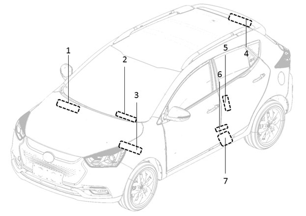
1 Vehicle identification label (front tire cover) VIN
2 Vehicle identification label (inside glove box) VIN
3 Vehicle identification label (air window) VIN
4 Vehicle identification label (lower part of right B column) VIN
5 Vehicle identification label (left front door frame) VIN
6 Tire pressure label (lower part ofleft B column)
7 Product label (lower part of front door)
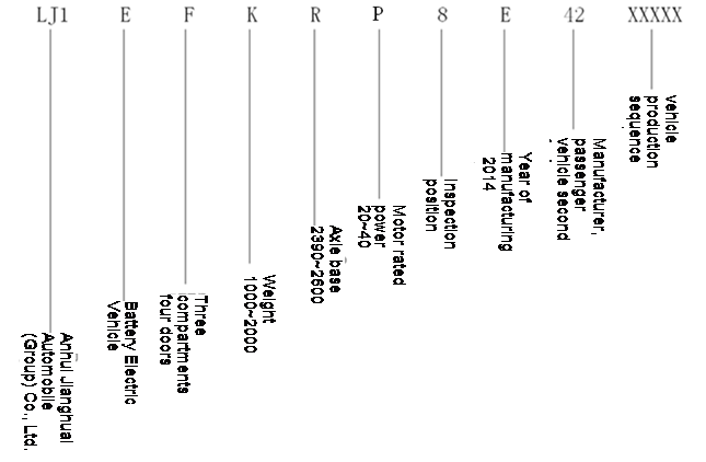
VEHICLE IDENTIFICATION NUMBER FORMATION (VIN)
Anhui Jianghuai Automobile Co.Ltd.; electric vehicle; four-door sedan; weight; wheelbase; rated power of motor; check digit; production year; manufacturing plant the second PV factory; vehicle serial number
IDENTIFICATION PLATE
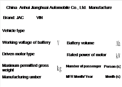
MOTOR SERIAL NUMBER
![]()
![]()
![]()
![]()

Dimensions
|
Items |
Parameters (mm) |
|
Overall length |
4135 |
|
Overall width |
1750 |
|
Overall height |
1560 |
|
Wheelbase |
2490 |
|
Front tread |
1515 |
|
Rear tread |
1500 |
Wheels & Tires
|
Wheels |
6.5J×16 |
|
Tires |
205/55R16 |
PRECAUTION
PRECAUTIONS
Please obey the following precautions to ensure safe and proper servicing.These precautions are not described in each individual section.
Precautions for Technicians Using Medical Electric
Warning
l Parts with strong magnet are used in this vehicle.
l Technicians using a medical electric device such as pacemaker must never perform operation on the vehicle as strong magnetic parts can affect the device function.
Normal Charge Precaution
Warning
l If technicians use a medical electric device such as an implantable cardiac pacemaker a cardioverter or defibrillator the device function must be checked before starting the charging.
l If technicians use a medical electric device such as an implantable cardiac pacemaker a cardioverter or defibrillator must not enter the vehicle compartment (including luggage room) during charging.
Precaution at telematics system operation
l If technicians use a medical electric device such as an implantable cardiac pacemaker a cardioverter or defibrillator please keep enough distance with telematics system.
l The electromagnetic wave of remote intelligent terminal might affect the function of medical electric devices such as an implantable cardiac pacemaker a cardioverter or defibrillator.
l If technicians use a medical electric device such as an implantable cardiac pacemaker a cardioverter or defibrillator the electromagnetic wave of remote intelligent terminal might affect the function.The possible effects on the devices must be checked with the device manufacturer before remote intelligent terminal using.
Key Point to be Checked Before Maintenance Work
The high voltage system may starts automatically.It is required to check that the timer air conditioner and timer charger are not set before maintenance work.
Note
If the timer air conditioner and timer charger are set the high voltage system starts automatically even when the power switch is OFF.
Precaution for Supplemental Restraint System (SRS) “AIR BAG” and “SEAT BELT PRE-TENSIONER”
The Supplemental Restraint System “AIR BAG” and “SEAT BELT PRE-TENSIONER” used along with a front seat belt helps to reduce the severity of injury to the driver and front passenger in collision.This system includes seat belts and air bags of driver and front passenger.For detailed information please see Chapter “AIR BAG” and “SEAT BELT”.
Warning
Always observe the following items for preventing accidental activation
l To avoid the SRS failure and collision accident after the failure which could cause personal injury or death all maintenance must be performed by an authorized JAC dealer.
l Improper maintenance including incorrect removal and installation can lead to personal injury caused by unintentional activation of the SRS.For removal of air bag module please see “AIR BAG SYSTEM”.
l Never use any electrical test equipment on any circuit related to the SRS unless instructions in this Service Manual.SRS wiring harness can be identified by yellow and /or orange harness
Precautions When Using Power Tools (Air or Electric) and Hammers
l When working near the Air Bag Diagnosis Sensor Unit or other Air Bag System sensors with the power switch on never use air ot electric power tools or strike near the sensors with a hammer.Heavy vibration could activate the sensor and deploy the air bag possibly causing serious injury.
l When using power tools or hammers always switch the power switch OFF disconnect the 12V plumbic acid battery and wait at least 1 minute before performing any service.
Precautions for Removing 12 V Battery 12V
Before remove the 12V battery switch the key to “ON” and then turn to “LOCK”.
Note
l The automatic charging of 12V battery could also be started even when the key is in “LOCK”.
l The automatic charging of 12V battery would not be started when the key is turned from “ON” to “LOCK”.
|
l Before jacking up the vehicle apply wheel chocks or other tire blocks to the wheels to prevent the vehicle from moving.After jacking up the vehicle support the vehicle weight with safety stands at the points designated for proper lifting before working on the vehicle.This operation should be done on a level surface. |
|
|
l When removing a heavy component such as battery pack or power train be careful not to lose your balance and drop them.Also do not allow them to strike adjacent parts especially the brake pipes and brake master pump. |


l Before the service work which do not need to use power put the key in “LOCK” and cut off the negative pole of 12V battery.
l After cutting off the negative pole of 12V battery the restored memory of radio and other control units will be erased.
l Dispose of drained oil or the solvent used for cleaning parts in an appropriate manner.
l Clean all disassembled parts in the designated liquid or solvent prior to inspection or assembly.
l Replace oil seals gaskets seal rings O-rings locking washers cotter pins self-locking nuts etc.with new ones.
l Replace inner and outer races of tapered roller bearings and needle bearings as a set.
l Arrange the disassembled parts in accordance with their assembled locations and sequence.
l After disconnecting vacuum or air hoses attach the tag to indicate the proper connection.
l Use only the fluids and lubrications specified in this manual.
l Use approved bonding agent sealants or their equivalents when required.
|
l Use hand tools power tools (disassembly only) and recommended special tools where specified for safe and efficient service repairs. |
|
|
l When repairing the fuel oil water vacuum or exhaust systems check all affected lines for leakage. |
|


Before servicing the vehicle
Protect fenders upholstery and carpeting with appropriate covers.Take caution that keys buttons or similar things do not scratch paint.
Hose Removal and Installation
|
l To prevent damage to rubber hose do not pry off rubber hose with tapered tool or screwdriver. |
|
|
l To reinstall the rubber hose securely check that hose insertion length and orientation of clamp is correct.(If tube is equipped with hose stopper insert rubber hose into tube until it butts up against hose stopper.)
|
|
|
|
|


Hose Clamping
|
l If old rubber hose is re-used, install hose clamp in its original position (at the indentation where the old clamp was). If there is a trace of tube bulging left on the old rubber hose, align rubber hose at that position. l Discard old clamps; replace with new ones. l
|
|


CAUTIONS AS TO HIGH VOLTAGE
Be sure to follow the procedure below and shut off the high voltage before performing inspection or servicing of the high voltage system.
|
1 Turn power switch OFF. 2 Disconnect 12V battery negative terminal. 3 Disconnect service plug following below procedure a、 Open the carpet cover above the service switch
|
|
|
b、 Remove the installation bolts of service cover and take the service plug cover off |
|
|
c、 Open the service plug second buckle |
|
|
d、 Turn the service plug handle according to the direction in picture and then remove the service plug. |
|


|
|
Danger touch high voltage components without using the appropriate protective equipment will cause electrocution. |
|
Warning
l Immediately protect high voltage connectors and terminals with insulating tape.
l Do not allow other people to operate the service plug.
4 Wait for a minimum of 10 minutes after the service plug is removed.
1 Check that 12V battery is disconnected.
2 Connect the service plug
3 Press the second buckle
4 Close the service plug cover and fix with bolts
5 Close the carpet cover on the position of service plug
|
|
Danger touch high voltage components without using the appropriate protective equipment will cause electrocution. |
|
Warning
l Immediately protect high voltage connectors and terminals with insulating tape.
l Do not allow other people to operate the service plug.
Warning
l Because electric vehicles contain a high voltage battery there is risk of electric shock electric leakage or similar accidents if the high voltage component and vehicle are handles incorrectly be sure to follow the correct work procedures when performing inspection and maintenance.
l Must turn the key to “LOCK” or pull it out before disconnecting service plug.
l Disconnect the service plug before inspection or maintenance of high voltage system and do not allow anyone close service plug during the inspection and maintenance.Be sure to wear insulating protective equipment consisting of glove shoes and glasses before beginning work on the high voltage system.
l Be sure that other people do not touch the vehicle when service man is operating high voltage system.When not working cover high voltage parts with an insulating cover sheet to prevent other people from contacting them.
l After disconnecting the service plug must not put the key in “ON” or turn to “START” gear.
High Voltage Harness and Safety Mark
The colors of all high voltage harness are orange.Safety mark is applied to the battery pack and other high voltage devices so do not touch these harness and components..
Handling of High Voltage Harness Terminals
Immediately insulate disconnected high voltage harness connectors with insulating tape.
Regulations on Workers with Medical Electronics
The vehicle contains parts that contain power magnets.If a technician who is wearing a pacemaker or other medical devices is close to these parts the medical device may be affected by the magnets.So such persons must not perform service work on the vehicle.
Prohibited Items to Carry During the Work
Because this vehicle uses components that contain power magnetism do not carry any metal products which may cause short circuits or any magnetic media (cash cards prepaid cards etc.) which may be damaged with you when working.
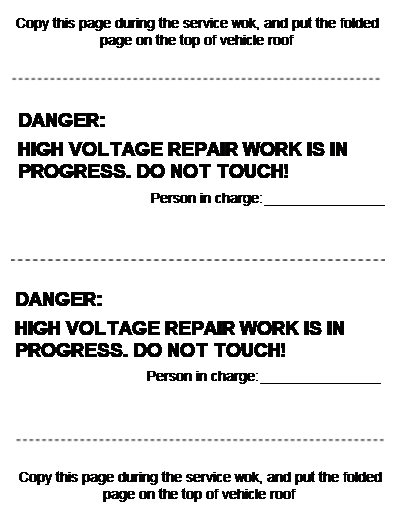
Post the Warning Label of "HIGH VOLTAGE COMPONENTS IN REPARING DO NOT TOUCH"
To call the attention of other workers indicate “High voltage work in progress.Do not touch!” on vehicles where work is being performed on the high voltage systems.
DANGER
HIGH VOLTAGE REPAIR WORK IS IN PROGRESS.DO NOT TOUCH!
Person in charge _________________
Copy this page during the service wok and put the folded page on the top of vehicle roof
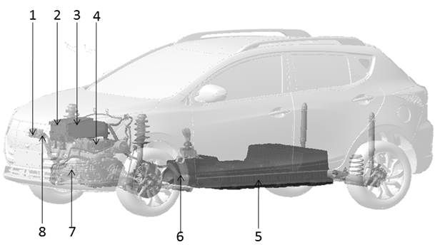
Layout of High Voltage Components
|
No. |
Position of Parts |
|
1 |
DC charging socket |
|
2 |
Drive control device |
|
3 |
High voltage distribution device |
|
4 |
On board charger |
|
5 |
Power cell assembly |
|
6 |
High voltage main cable assembly |
|
7 |
Drive motor assembly |
|
8 |
AC charging socket |
If there are parts in this sheet attached with high-voltage labels.at time when a part needs to be replaced or when a label had become peeled be sure to apply the new label in the same position and facing in the same direction.
Insulated Protective Wear and Insulating Tools
Perform an inspection before beginning work to ensure there is no abnormal problem of the protective devices.
This inspection is performed before and after use the worker need to check for deterioration and damage of these protective devices.
l Insulated gloves
Inspect the insulated gloves for scratches holes and tears.(Visual check and air leakage test)
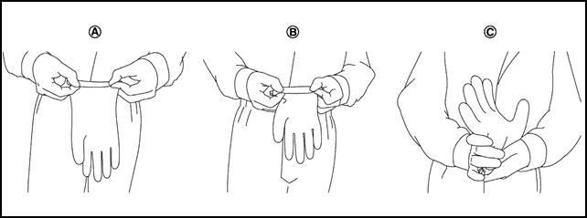
A. Hold glove and fold as shown in the figure
B. Fold three or four times preventing air from escaping from the glove
C. Squeeze glove to check that the glove has no holes
Insulated safety shoes
Inspect the insulated safety boots for holes scratch nails metal pieces wear or other damages.(
Insulating Tools
When performing work at locations where high voltage is applied use insulated tools.
Preparation items
|
Description |
Purpose |
|
|
Insulated gloves |
Can bear 1000V/300A 1000V/300A |
To protect people from high voltage electric shock |
|
Insulated shoes |
— |
|
|
Safety glasses |
— |
|
|
Wrenches |
— |
1. To remove 12V battery negative terminal bolts 12V 2. To remove mounting bolts of the service plug cover |
|
Heat proof solvent resistance protection gloves and shoes |
Heat proof solvent resistance protection tools |
To utilize when the battery electrolytic solution leaks |
|
Mat and cloth |
|
To absorb the battery electrolytic solution leakage |
|
Extinguisher |
Type ABC for electrical fire |
To extinguish a fire |
|
Megohmmeter |
To measure at least 500V |
To measure voltage on damaged harness and high-voltage parts |
|
Insulated tape |
For insulating protection |
To cover the damaged high-voltage harness to protect from electric shock |
How to Handle Damaged Vehicles in Specified Conditions
High voltage system shut-down procedure
The first step for a damaged vehicle is to shut down high voltage system.Any of the following procedures can shut down the high voltage system.
If the vehicle is heavily damaged for example the battery is deformed broken or cracked insulating protective wear must be used and otherwise you must not touch the high voltage harness.
|
|
l If the charging harness is connected with the vehicle remove it. |
|
|
l To prevent from serious injury or death caused by electric shock must cut off the high voltage before dispose the damaged vehicle.Must not touch high voltage harness or parts with bare hands. |
|
|
l When contact with high voltage parts or harness is unavoidable or when there is risk of such contact be sure to wear insulating protective gloves. |
Caution
l Before disconnecting the 12V battery negative terminal if necessary lower the windows unlock the doors and open the back door.Once the 12V battery is disconnected those operations will not be performed.

Warning
l Be sure the high voltage system is disconnected when the key is in “LOCK” or “ACC”.
l Be sure the remote air conditioner remote charging and timing charge are OFF.
l The high voltage full discharged takes 10 minutes.And please wait for 10 minutes to complete discharging the high voltage.While waiting do not do any operation.
l After removing the 12V battery negative terminal do not be close to air bag within 1 minute.Otherwise there is a possibility of air bag explosion due to short circuit or damage and it may cause serious injuries.
Indications the high voltage system is ON
l If the READY indicator is ON the high voltage system is active.READY
l If the air conditioning indicator is ON the high voltage system is active.
l If the charging indicator is ON the high voltage system is active.
Procedure 1 Turn the key to “LOCK”
1 Check the state of READY indicator if it is ON the high voltage system is active.READY
2 Be sure the READY indicator lamp is OFF.
3 Disconnect the 12V battery negative terminal.Insulate the battery negative terminal with insulated tape.
4 Wait 10 minutes to complete discharging the high voltage condenser after the power switch has been turned OFF.
5 Perform the first response action for emergencies.
Procedure B Remove the fuses.(If power switch cannot be turned OFF)
1 Open the electronics box hood in front compartment.
2 Remove self-hold fuse.
3 If it cannot identify the above fuses remove all fuses in the fuse box.
4 Disconnect the 12V battery negative terminal.Insulate the battery negative terminal with insulated tape.
5 Wait 10 minutes to complete discharging the high voltage condenser after the power switch has been turned OFF.
6 Perform the first response action for emergencies.
Warning
|
|
l Do not turn the power switch ON while fuses are being removed. |
|
|
l To avoid unintended installation and risk of electric shock the serviceman should carry the fuses on himself/herself and do insulating treatment to the fuse box. |
Procedure 3 Disconnect the service plug (when Procedure A and Procedure B are impossible and the use of insulating rubber gloves is possible)
Warning
|
|
l Do not remove the service plug without wearing protective equipment to prevent any serious injury or death by electric shock. |
1 Disconnect service plug
|
a、 Open the carpet cover above the service switch
|
|
|
b、 Remove the installation bolts of service cover and take the service plug cover off |
|
|
c、 Open the service plug second buckle |
|
|
d、 Turn the service plug handle according to the direction in picture and then remove the service plug. |
|
2 Wait 10 minutes to complete discharging the high voltage condenser after the power switch has been turned OFF.
3 Perform the first response action for emergencies.
Warning
If it is possible use large amount of water from a fire hydrant to extinguish the fire.Do not use a small amount of water because small amount of water will make toxic gas produced by a chemical reaction between battery electrolyte and water.
Warning
Any absorbent mats r cloths use to wipe electrolyte must be disposed of as industrial waste as required by federal law.
l In case of electrolyte solution leakage wear insulating protective devices and wipe with a dry cloth.
l The battery electrolyte solution is clear color and has a pungent smell.Do not touch the electrolyte.
l The battery electrolyte solution is flammable.In case of leakage please keep properly ventilation.
l In case electrolyte solution comes in contact with eyes rinse plenty of running water and see a doctor immediately.
The battery pack must be removed from the vehicle before it is scrapped.
Warning
Insulate the high voltage terminals of the removed battery with insulating tape.
Handling of a Vehicle with a Faulted Battery
For the handling of a vehicle when the battery is dead refer to “Truck Towing” chapter.
LIFTING OF VEHICLE
|
Tool name |
Description |
|
Board lifting jack attachment |
|
|
Safety stand attachment |
|


![]() Caution
Caution
l Every time the vehicle is lifted up maintain the complete vehicle curb condition.
l Since the vehicle’s center of gravity changes when removing main parts on the front side (engine transmission suspension etc.) support a jack up or equivalent tools point on the front or rear side of the vehicle..
l Be careful not to squeeze harness cables or pipelines.
Jack Safety Stand and 2-Pole Lift
Warning
l Park the vehicle on a level surface when using the jack.Check to avoid damaging pipes cables etc.under the vehicle.
l Never get under the vehicle while it is supported only by the jack.Always use safety stands when you have to get under the vehicle.
l Place wheel chocks at both front and back of the wheels on the ground.
l When lifting the vehicle open the lift arms as wide as possible and ensure that the front and rear of the vehicle are well balanced.
l When setting the lift arm never allow the arm to contact the brake pipes charging harness lower fence of battery.
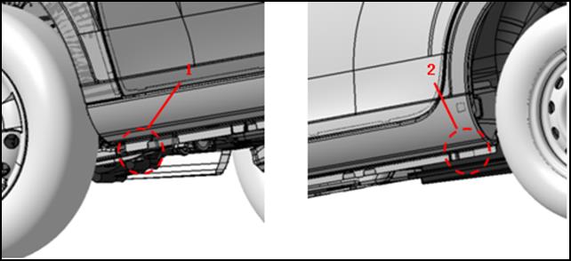
|
1 safety stand point and lift up point (front) |
2 safety stand point and lift up point (rear) |
Caution check the vehicle is empty when lifting.
TRUCK TOWINGl It is necessary to use proper towing equipment to avoid possible damage to the vehicle during towing operation. l When towing make sure that the axles steering system and powertrain are in working condition.If any unit is damaged a flatbed must be used. If you need to tow the vehicle please contact with JAC authorized dealer or professional towing service company.Improper towing methods may damage the vehicle. |
|

Three normal methods to tow the vehicle
l Flatbed — operator will load your vehicle on the truck.This is the best way to transport your vehicle.See picture (1).
l Carry the wheels — the method is to use two towing arms to insert the bottom of wheels (front) and carry them off the ground with other two tires still remained on the ground.See picture (2).
l Lifting — this method is to use metal cables with hook at the end and put the hook on frame or suspension to hang the front of vehicle off the ground by the cable.But this method is not available because it may seriously damage you vehicle or its suspension.See picture (3).
Vehicle Recovery ( Freeing a Stuck Vehicle)
Front
|
l Only use towing hook but no other parts.Otherwise the vehicle body will be damaged. l Only use the vehicle towing hook to free a vehicle stuck in sand snow mud etc.Never tow the vehicle for a long time. l When free a stuck vehicle the towing hook will bear a large force.So always pull the cable straight out from the front of the vehicle.Never pull on the hook at an angle. l Stand clear of a stuck vehicle. |
|

Warning
l Never spin your tires at high speed.This could cause them to explode and result in serious injury.Parts of your vehicle could also overheat and be damaged.
l Use wheel nut wrench to tightly assemble the dismountable towing hook.
Rear

SERVICE INFORMATION FOR CIRCUIT FAULTS
How to Effiently Diagnose Circuit Fault
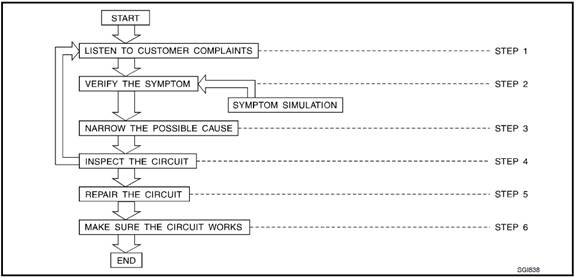
Work Flow
|
Step |
Description |
|
Step 1 |
Get detailed information about the conditions and the environment when the fault occurred The following are key pieces of information required to make a good analysis |
|
WHAT vehicle model engine vehicle controller battery management system and other systems (air conditioner). |
|
|
WHEN time date weather condition frequency. |
|
|
WHEN road conditions altitude and traffic situation. |
|
|
HOW system symptoms operating conditions (other components interactions). Service history and if any after market accessories have been installed. |
|
|
Step 2 |
Operate the system road test if necessary; Verify the parameter of the fault; If the problem cannot be duplicated refer to “Fault Simulation Tests”. |
|
Step 3 |
Collect the proper diagnosis materials together including l Power supply routing l System operation description l Applicable service manual sections l Check for any service bulletins Identify where to begin diagnosis based on your knowledge of the system operation and the customer comments. |
|
Step 4 |
Check the system for mechanical binding loose connectors or wiring damage. Determine which circuits and components are involved and diagnose using the power supply routing and harness layouts. |
|
Step 5 |
Repair or replace the faulted circuit or components. |
|
Step 6 |
Operate the system in all modes.Verify the system works properly under all conditions.Check you have not inadvertently created a new fault during your diagnosis or repair steps. |
Control Units and Electrical Parts
Precautions
l Never reverse battery terminals.
l Install only parts specified for a vehicle.
l Before replacing the control unit check the input and output functions of the components.
l Do not apply excessive force when disconnecting a connector.
l Do not drop or strike control unit.
|
l Be careful to prevent condensation in the control unit due to rapid temperature changes and do not let water or rain get on it.If water is found in the control unit dry it fully and then install it in the vehicle. |
|
|
l Be careful not to let oil get on the control unit connector. |
|
|
l Avoid cleaning the control unit with volatile oil. l Do not disassemble the control unit and do not remove the upper and lower covers. l when using a multimeter be careful not to let test probes get close to each other to prevent the power transistor in the control unit from changing battery voltage because of short circuiting. |
|


l When checking input and output signals of the control unit use the specified check adapter.
How to Check Connectors
l During circuit checks improper operation can cause connector damage or intermittent connection.
l The probe of a digital multimeter (DMM)may not correctly fit the connector cavity.To correctly probe the connector follow the procedures below using a T pin.For the best contact grasp the T pin using an alligator clip.
Measuring from Harness Side
|
Standard type (not waterproof type) connector should be measured from harness side with T pin.“T” l If the connector has a rear cover such as a ECM connector remove the rear cover before measuring the terminal. l Do not measure waterproof connector from harness side.Otherwise it may damage the seal ring in the connector. |
T pin Connector Alligator clip |

Measuring from Terminal Side
Female terminal
|
l There is a small notch above each female terminal and probe each terminal with the T pin through the notch.Do not insert unmatched terminals of male terminal. |
Sectional
view (female) T pin |
||||
|
l Some connectors do not have a notch above each terminal.To probe each terminal remove the connector retainer to make contact space for probing. |
Retainer |


Male terminal
|
l Carefully probe the contact surface of each terminal using a T pin.“T”
|
Sectional
view (male) T pin Male
terminal |

Caution
Never bend terminal.
How to Check Poor Contact of Terminal
l Poor contact of terminal may create intermittent signals in the circuit.
l If the intermittent open circuit occurs follow the procedure below to inspect for open wires and poor contact.
|
1 Prepare a male terminal and 10cm of wire.10CM Caution Use a male terminal which matches the female terminal. 2 Disconnect the suspected faulty connector and hold it terminal side up. |
Wire Male terminal |
||||
|
3 While holding the wire of the male terminal try to insert the male terminal into the female terminal. Caution Never force the male terminal into the female terminal with your hands. |
Do not apply force against the
terminal. |
||||
|
4 While moving the connector check whether the male terminal can be easily inserted or not. |
|
||||
|
l If the male terminal can be easily inserted into the female terminal replace the female terminal. |
Unqualified Qualified |


Waterproof Connector Inspection
If water waters the connector it can short interior circuits.This may be a common problem.
Check the flowing items to maintain the original waterproof characteristics.
Rubber Seal Inspection
|
l Most waterproof connectors are provided with a rubber seal between the male and female connectors.If the seal is missing the waterproof performance may not meet specifications. |
Rubber
seal Wire
seal Connector
housing |
||||||
|
l The rubber seal may come off when connectors are disconnected.Whenever connectors are reconnected make sure the rubber seal is properly installed on either side of male or female connector. |
|
||||||
|
Waterproof Plug Inspection l The waterproof plug must be installed on the crimping area of harness and terminal.Be sure that the waterproof plug is installed properly. |
|


Terminal Self-lock Inspection
l check if the terminal is locked by pulling wire at the end of connector.An unlocked terminal may create poor contact of harness.
Fault Simulation Test
Introduction
Sometimes the symptom is not present when the vehicle is brought in for service.So we have to re-create the conditions present at the time of the fault.Doing so may help avoid unnecessary fault diagnosis.The following section illustrates ways to simulate the conditions/ environment under an electrical fault.This section is divided into six following topics
l Vehicle vibration
l Heat sensitive
l Freezing
l Water intrusion
l Electrical load
l Cold or hot start up
Get a thorough description of the fault from the customer.It is important for simulating the conditions of the problem.
The problem may occur or become worse while driving on a rough rod or when engine A/C compressor is vibrating.In such a case you will want to check for a vibration related condition.Refer to the following illustration.
Determine which connectors and wiring harness would affect the electrical system you are inspecting.Gently shake each connector and harness while monitoring the system for whether the fault will occur again.This test may indicate a loose or poor electrical connection.
Connectors can be exposed to moisture.It is possible to get a thin film of corrosion on the connector terminals.A visual inspection may not reveal this without disconnecting the connector.If the problem occurs intermittently perhaps the problem is caused by corrosion.It is a good idea to disassemble inspect and clean the terminals on related connectors in the system.
Sensor & Relay
Gently shake the sensors and relays in the system you are inspecting.
This test may indicate a loose or poorly mounted sensor or relay.

There are several reasons a vehicle or motor vibration could cause an electrical complaint.Some of the things to check for are
l Connectors not fully seated.
l Wiring harness not long enough and is being stressed due to engine vibration or shaking.
l Wires laying across brackets or moving components.
l Loose dirty or corroded ground wires.
l Wires routed too close to hot components.
To inspect components under the hood start by verifying the integrity of ground connections.(Refer to “Ground Inspection” described later.) First check that the system is properly grounded.The check for loose connection by gently shaking the wiring or components as previously explained.Using the wiring diagrams inspect the wiring for continuity.()
An improperly routed or improperly clamped harness can become pinched during accessory installation.Vehicle vibration can damage a harness which is routed along a bracket or near a screw.
An unclamped or loose harness can cause wiring to be pinched by seat components such as slide guides during vehicle vibration.If the wiring runs under the seats inspect wire routing for possible damage or pinching.
|
Sometimes customers may have this problem during hot weather or after car has sat for a short time.In such cases you will want to check for a heat sensitive condition. |
Heating test Heat gun Do not heat above 60℃ (140°F) |

To determine if an electrical component is heat sensitive heat the component with a heat gun or equivalent.
Caution
Never heat components above 60°C(140°F).60°C(140°F)
If fault occurs while heating the unit either replace or properly insulate the component.
|
The customer may indicate the fault goes away after the car warms up (winter time).The cause could be related to water freezing somewhere in the wiring/ electrical system. |
Solenoid Water in connector Freezing test Short-circuit |

Two methods to check
The first is to arrange for the owner to leave the car overnight.Check it will get cold enough to demonstrate his complaint.Leave the car parked outside overnight.In the morning do a quick and thorough diagnosis of those electrical components which could be affected.
The second method is to put the suspect component into a freezer long enough for any water to freeze.Reinstall the part into the car and check for the reoccurrence of the fault.If it occurs repair or replace the component.
|
The fault may occur only during high humidity or in rainy/ snowy weather.In such cases the fault could be caused by water intrusion on an electrical part.This can be simulated by soaking the car or running it through a car wash. |
Water intrusion test |

Caution
Never spray water directly on any electrical components.
|
the fault may be electrical load sensitive.Perform diagnosis with all accessories (including A/C rear window defogger radio fog lamps) turned on. |
Rear window
defogger Light switch Electrical load test |

On some occasions an electrical fault may occur only when the car is started cold or it may occur when the car is restarted hot shortly after being turned off.In these cases you may have to keep the car overnight to make a proper diagnosis.
Circuit Inspection
Description
In general testing electrical circuits is an easy task if it is approached in a logical and organized method.First it is important to have all available information on the system to be tested.Also get a thorough understanding of system operation.Then you will be able to use the appropriate equipment and follow the correct test procedure.
You may have to simulate vehicle vibrations while electrical components.Gently shake the wiring harness or electrical components to do this.
|
Open |
A circuit is open hen there is no continuity through a section of the circuit. |
|
Short |
There are two types of shorts. |
|
Short Circuit When a circuit contacts another circuit and causes the normal resistance to change. |
|
|
Short to Ground When a circuit contacts a ground source and grounds the circuit. |
Note
Please refer to “How to Check Terminal Port” to probe or inspect terminal port.
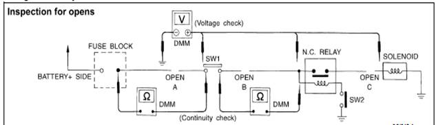
Testing for “Opens” in the Circuit
Before you begin to diagnose and test the system you should rough sketch a schematic of the system.This will help you to logically walk through the diagnosis process.Drawing the sketch will also reinforce your working knowledge of the system.
Continuity check method
The continuity check is used to find an open in the circuit.The digital multimeter (DMM) set on the resistance function will indicate an open circuit as over limit (no beep tone or no ohms symbol).Check to always start with the DMM at the highest resistance level.
To help in understanding the diagnosis of the open circuits please refer to the previous schematic.
l Disconnect the battery negative terminal.
l Start at one end of the circuit and inspect to the other end.(At the fuse block in this example)
l Contact one probe of the DMM to the fuse block terminal on the load side.
l Contact the other probe to the fuse block (power) side of SW1.Little or no resistance will indicate that portion of the circuit has good continuity.If there were an open in the circuit the DMM would indicate an over limit or infinite resistance condition.(point A)
l Connect the probes between SW1 and the relay.Little or no resistance will indicate that portion of the circuit has good continuity.If there were an open in the circuit the DMM would indicate an over-limit or infinite resistance condition.(point B)
l Connect the probes between the relay and the solenoid.Little or no resistance will indicate that portion of the circuit has good continuity.If there were an open in the circuit the DMM would indicate an over-limit or infinite resistance condition.(point C)
Any circuit can be diagnosed using the approach in the previous example.
Voltage Check Method
To help in understanding the diagnosis of open circuits please refer to the previous schematic.
In any powered circuit an open can be found by methodically checking the system for the presence of voltage.This is done by switching the DMM to the voltage function.
l Connect one probe of the DMM to a known good ground.
l Begin probing at one end of the circuit and inspect to the other end.
l With SW1 open probe at SW1 to check for voltage.SW1
Voltage the open is further down the circuit than SW1.
No voltage the open is between fuse block and SW1 (point A).
l Close SW1 and probe at relay.SW1
Voltage the open is further down the circuit than the relay.
No voltage the open is between SW1 and the relay (point B).
l Close the relay and probe at the solenoid.
Voltage the open is further down the circuit than the solenoid.
No voltage the open is between the solenoid and the relay (point C).
Any circuit can be diagnosed using the approach in the previous example.
Testing for “Shorts” in the Circuit
To simplify the discussion of shorts in the system please refer to the following schematic.

l Disconnect the battery negative terminal and remove the blown fuse.
l Disconnect all loads (SW1 open relay disconnected and solenoid disconnected) powered through the fuse.
l Connect one probe of the DMM to the load side of the fuse terminal.Connect the other probe to a known good ground.
l With SW1 open check for continuity.SW1
Continuity the short is between fuse terminal and SW1 (point A)
No continuity the short is further down the circuit than SW1.
l Close SW1 and disconnect the relay.Put probes at the load side of fuse terminal and a known good ground.Then check for continuity.
Continuity the short is between SW1 and the relay (point B)
No continuity the short is further down the circuit than the relay,
l Close SW1 and jump the relay contacts with jumper wire.Put probes at the load side of fuse terminal and a known good ground.Then check for continuity.
Continuity the short is between the relay and the solenoid (point C)
No continuity check solenoid back to the check.
l Remove the blown fuse and disconnect all loads (i.e.SW1 open relay disconnected and solenoid disconnected) powered through the fuse.
l Turn the power switch to the ON or START position.Verify battery voltage at the battery + side of the fuse terminal (one probe on the battery + terminal side of the side block and one probe on a known good ground).
l With SW1 open and the DMM probes across both fuse terminals check for voltage.SW1
Voltage the short is between fuse block and SW1 (point A)
No voltage the short is further down the circuit than SW1.
l With SW1 closed relay and solenoid disconnected and the DMM probes across both fuse terminals check for voltage.SW1
Voltage the short is between SW1 and the relay (point B).
No voltage the short is further down the circuit than the relay.
l With SW1 closed relay contacts jumped with fused jumper wire and then check for voltage.
Voltage the short is down the circuit of the relay or between the relay and the disconnected solenoid (point C).
No voltage back to the checking steps and check power of fuse block.
Ground connections are very important to the proper operation of electrical and electronic circuits.Ground connections are often exposed to moisture dirt and other corrosive elements.The corrosion (rust) can become an unwanted resistance.This unwanted resistance can change the way a circuit works.
Controlling signal circuits are very sensitive to proper grounding.A loose or corroded ground can drastically affect an controlling signal.A poor or corroded ground can easily affect the circuit.Even when the ground connection looks clean there can be a thin film of rust on the surface.
When inspecting a ground connection please follow these methods
l Remove the ground bolt or screw.
l Inspect all mating surfaces for tarnish dirt rust etc.
l Clean as required to assure good contact.
l Reinstall bolt or screw tightly.
l Inspect for “add-on” accessories which may be interfering with the ground circuit.“ ”
l If several wires are crimped into one ground plate check for proper crimps.Check all of the wires are clean fastened providing a good ground path and with no excess wire insulation.
For detailed ground distribution information refer to “Ground and Loop” section.

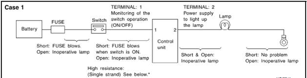
Voltage drop tests are often used to find components or circuits which have excessive resistance.A voltage drop in a circuit is caused by a resistance when the circuit is in operation.
Check the wire in the following picture.When measuring resistance with DMM contact by a single strand of wire will give reading of 0 ohms.This indicates a good circuit.But when the circuit operates this single strand of wire is not able to carry the current.The single strand will have a high resistance to the current.This will produce a slight voltage drop.
Unwanted resistance can be caused by many situations as follows
l Undersized wiring (i.e.single strand)
l Corrosion on switch contacts
l Loose wire connections or splices.
During the repair always use wire that is of the same or larger gauge.
Measuring Voltage Drop---Accumulating Method
l Connect the DMM across the connector or part of the circuit you want to check.The positive probe of the DMM should be closer to power and the negative probe closer to ground.
l Operate the circuit.
l The DMM will indicate how many volts of the circuit.
Note in the illustration that there is an excessive 4.1 volt drop between the battery and the bulb.

Measuring Voltage Drop --- Step by Step
The step-by-step method is most useful for checking excessive drops in low voltage systems.
Operation current of controlling system is very low.
The controlling system operations can be adversely affected by any variation in resistance in the system.Such resistance variation may be caused by poor connection improper installation improper wire gauge or corrosion.
The step-by-step voltage drop test can identify a component or wire with too much resistance.

System description when the switch is ON the control unit lights up the lamp.“ON”
|
Terminal No. |
Items |
Condition |
Value [V] |
In case of high resistance such as single strand [V] * |
|
1 |
Switch |
Switch ON |
Battery voltage |
Lower than battery voltage approx.8 (Example) |
|
Switch LOCK |
Approx.0 |
Approx.0 |
||
|
2 |
Lamp |
Switch ON |
Battery voltage |
Approx.0 (inoperative lamp) |
|
Switch LOCK |
Approx.0 |
Approx.0 |
The voltage value is based on the body ground.
*If high resistance exists in the switch side circuit (caused by a single strand) then terminal 1 could not detect battery voltage.Control unit could not detect the switch is ON or not even if the switch is already in ON.Therefore the control unit does not supply power to light up the lamp.
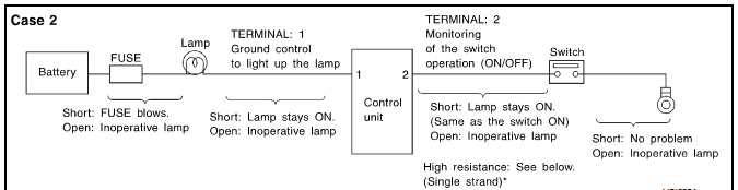
|
Terminal No. |
Items |
Condition |
Value [V] |
In case of high resistance such as single strand [V] * |
|
1 |
Lamp |
Switch ON ON |
Approx.0 |
Battery voltage (inoperative lamp) |
|
Switch LOCK |
Battery voltage |
Battery voltage |
||
|
2 |
Switch |
Switch ON |
Approx.0 |
Higher than 0 approx.4 Approx.4 (Example) |
|
Switch LOCK |
Approx.5 |
Approx.5 |
The voltage value is based on the body ground.
*If high resistance exists in the switch side circuit (caused by a single strand) then terminal 2 could not detect approx.0V battery voltage.Control unit could not detect the switch is ON or not even if the switch is already in ON.Therefore the control unit does not provide ground connection signal to light up the lamp.
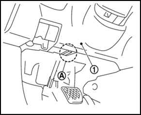
DIAGNOSTIC TOOL CHECKING SYSTEM FOR NEW ENEERGY VEHICLE
Description
l When the diagnostic tool is connected with the vehicle OBD (A) it will communicate with the control unit and do the diagnostic tests.OBD(A)
1:Left lower of instrument panel
l Refer to “Diagnosis Operation Manual of New Energy Vehicle” for more detailed information.