Precaution for Technicians Using Medical Electric
Key Part Check before Maintenance and Repair
Precautions for SRS "Air Bag" and "seat belt pre-tensioner
Precautions for removing 12V battery
Rearview Mirror Adjustment Switch
AUTOHOLD Switch(Such as Equipment)
Precaution for Technicians Using Medical Electric
Operation Prohibition
Warning:
Parts with strong magnet is used in this vehicle.
Technicians using a medical electric device such as pacemaker must never perform operation on the vehicle, as magnetic field can affect the device function by approaching to such parts.
Normal charge precaution
Warning:
If a technician uses a medical electric device such as an implantable cardiac pacemaker or an implantable cardioverter defibrillator, the possible effects on the devices must be checked with the device manufacturer before starting the charge operation.
As radiated electromagnetic wave generated by on board charger at normal charge operation may affect medical electric devices, a technician using a medical electric device such as implantable cardiac pacemaker or an implantable cardioverter defibrillator must not enter the vehicle compartment (including trunk) during normal charge operation.
Precaution at telematics system operation
If a technician uses implantable cardiac pacemaker or implantable cardioverter defibrillator (ICD), avoid the device implanted part from Communication device.
The electromagnetic wave of TCU might affect the function of the implantable cardiac pacemaker or the implantable cardioverter defibrillator (ICD), when using the service, etc.
If a technician uses other medical electric devices than implantable cardiac pacemaker or implantable cardioverter defibrillator (ICD), the electromagnetic wave of TCU might affect the function of the device. The possible effects on the devices must be checked with the device manufacturer before TCU use.
Key Part Check before Maintenance and Repair
Check the high-voltage system, and ensure the high-voltage system is powered off before starting the maintenance work, and disconnect the battery switch.
If the timer air conditioner or timer charge is set, the high voltage system starts automatically even when the power switch is in OFF state.
Precautions for SRS "Air Bag" and "seat belt pre-tensioner
Supplemental Restraint System (SRS) "Air Bag" and "seat belt pre-tensioner" are used on the front seat belts, which can help to reduce the dangers or serious injury of the driver and the front passenger in certain type of collisions. The relevant information of safe usage of the system are included in the SRS and Safety Belt Section of the Service Manual.
Warning:
In order to prevent accidents, please follow the below points:
Avoid the deactivation of SRS. Its failure will increase the personal injury caused by the airbag collision in the major collision accident. All the repairs must be done by the authorized dealer of JAC.
Improper repair, including wrong removal and installation of SRS system, will make the system unable to activate and cause personal injury. Regarding the spiral cable and airbag modules, please refer to "SRS AIR BAG".
Unless it is allowed in Service Manual, please do not use the electronic test equipment on the relevant circuit of SRS. The harness of SRS uses yellow or orange harness or harness connector, which can be easily recognized.
Precautions for using power tools (air or electric power) and hammers.
1) When the power switch is turned on, do not use the pneumatic or electric tools or hammer to hammer the surrounding areas of the airbag diagnostic sensor or airbag system sensors. Strong vibration may activate the sensors and unfold the air bag, which will cause serious injuries.
2) When using the pneumatic or electric tools or hammer, please switch off the power always, unplug the 12V lead-acid battery pile head, and wait at least 1 minute and then repair.
Precautions for removing 12V battery
Before removing the 12V battery, please turn the power switch to the ON position, then turn to the OFF position.
Tips:
When the power switch is on OFF position, the automatic charging control system of the battery may start.
When turning the power switch from ON position to OFF position, the automatic charging control system of the battery will not start.
Common Precautions
Before the serving, which is not need to use the power supply: turn the power switch to LOCK position, disconnect the 12V storage battery negative terminal.
After disconnecting 12V storage battery negative terminal, the storage memory of radio and other control devices will be deleted.
Place the removed components according to the assembly-oriented position and order.
If necessary, use authorized binder, sealant or equivalent product.
In order to repair the vehicle safely and efficiently, right use of hand tools, power tools(only for removal) and special tools is necessary.
Before Servicing:
Use suitable cover to cover the wheel fender, interior and carpet. Attention, do not use the key, fastener or the like to scratch the paintwork.
Instruction

Diagram of Combination Switch Assembly
1-Lamplight Control Switch 2-Self-Returning Switch 3-Wiper Control Switch
Lamplight Control Switch
The lamplight control switch controls the lamplight signal of left, right steering lamp, headlamp, front fog lamp, side turning lamp, overtaking lamp. As headlamp is under working mode, it also can realize two functions of turning high beam to low beam, turning low beam to high beam.
1) Steering Lamp
The steering signal operating lever has two upward (right steering) and two downward (left steering) positions. These positions are used to send out steering signals.
As steering signal needs to be sent out, push operating lever upward or downward to bottom. As steering is over, operating lever will return automatically. An arrow on the combination instrument will glitter, which displays the steering direction.
As lane changing signal needs to be sent out, push operating lever upward or downward to bottom and loosen it, as vehicle finishes changing lane, it will return automatically. As driver sends out steering or lane changing signal, if steering arrow flitters rapidly, which turns out to be that signal lamp has been damaged, other drivers can’t catch sight of steering signal. If some bulb has been damaged, please replace it to avoid traffic accidents. As driver sends out steering or lane changing signal, the steering arrow on instrument does not flitter, check the bulb for damage, then check fuse.
2) Headlamp/Dipped Headlamp Convertor
If headlamp needs to be turned from low beam to high beam, push steering signal/multifunctional operating lever forward. As high beam is connected, if you turn on ignition switch, combination instrument will display high beam signal.
If headlamp needs to be turned from high beam to low beam, push steering signal/multifunctional operating lever backward.
3) Overtaking Flash
This function can help driver make use of high beam headlamp to send out overtaking signal to front driver. As you make use of this function, pull steering signal/multifunctional operating lever backward until high beam is on, then loosen operating lever and make headlamp go out.
4) Front Fog Lamp
Turn front fog lamp switch to “ON” position, front fog lamp is on and front fog lamp signal displays on instrument. Only as front fog lamp switch stays “ON” position, driver can operate the rear fog lamp on sound control panel and rear fog lamp will be on.
Wiper Control Switch

1) Control working mode of wiper (washing, clearance, low speed, high speed).
As wiper stays on clearance gear, it has three modes to be selected: high, middle, low mode.
As ignition switch is connected, drive can operate front windshield wiper. Operate front windshield wiper by way of operating lever on the right side of steering column.
HI(High): Move operating lever to this position, wiper will scrape with high speed.
LO(Low): Move operating lever to this position, wiper will scrape stably with low speed.
INT(Intermittent): Move operating lever to this position, one cycle of scraping can be delayed.
Rotate middle section of wiper operating lever to LO direction, which can increase delay. Rotate wiper operating lever to HI direction, which can decrease delay. Only as operating lever stays on INT position, scraping speed can be adjusted.
2) Washing Liquid of Front Windshield
If you want to wash front windshield, as ignition switch has been connected, pull operating lever of washing liquid of front windshield wiper backward, washing liquid of front windshield wiper will be sprayed from front windshield nozzle.
3) Rear Wiper Switch
Rotate switch to ON position and start up rear wiper function.
Cautions:
When the weather is frozen, do not use the windscreen wiper if the front windshield has not been pre-heated. Otherwise the detergent will be frozen on the front windshield, which will obscure the driver’s vision.
As loosen operating lever, wiper will stop working, but it will still scrape for around three cycles, then it would stop scraping or recover to previous scraping speed.
Component Test
Check the conducting state for all the terminals of the wire connectors according to the following diagram. If the conducting state of all the wire connectors terminals is not in accordance with the following diagram, replace the switch.

 |
Replacement
Cautions:
Remove the battery negative terminal and wait for at least 3 minutes before removing the electrical appliance connectors, if not, the vehicle will be led to damage.
When removing and installing the component parts, please use rag to protect the component parts to be removed in case of damage.
Use the rag to wrap the crossed screwdriver blade when removing the metal clamps from the interiors.
Attention, do not damage the component parts.
When installing the body trim, ensure that the clamps are fixed tightly into the plate hole of the vehicle body, then press them into the plate hole carefully.
The removal and installation work on some large component parts can’t be finished by one person, therefore, in case of dropping, the work should be done by two persons.
Please do not apply a lot of pressure when installing and removing some interiors with the reason that they are able to be deformed.
1. Removal Step
1) Turn off the ignition switch, disconnect the storage battery negative terminal and wait for more than 3 minutes.
2) Remove the steering wheel.
3) Remove the upper and lower cover of the steering column cover.
4) Pull out the clock spring harness, remove the clock spring of the air bag.
5) Disconnect combination switch connector.

 |
6) Remove the two mounting bolts of the combination switch.

7) Pull out the combination switch assembly.


2. Installation Step
Install in the reverse order of removal.
Tightening torque of mounting bolts: 2 N·m
1. Operate the lamplight handle of the combination switch, test the working conditions for all the lamps and switches:
2. When the lamplight rotating handle is “OFF”, all the exterior illuminating lamps and the night illuminating lamps of the interior electrical appliance will turn off.
3. When the lamplight handle is in the small lamp position, the outline marker lamps, front and rear position lamps, license plate lamps, instrument illumination and all the night lamps of the interior electrical appliances will be on, if the vehicle is under driving state, the side marker lamps will be on in the meantime.
4. When the lamplight handle is in the small lamp position, press the front(rear) frog lamp switch, all the front(rear) frog lamp will be on.
5. When the lamplight handle is in the headlamp position, the headlamp lower beam will be on, while all the small lamps will keep lighted state, rotate the handle downward by 6 degrees, the high beam will be on instantaneously, the switch will automatically reset after releasing.
6. Rotate the lamplight handle forward(backward) by 15 degrees, all the right(left)steering lamps begin to flicker, while the right(left)steering indicator lamps on the instrument begin to flicker, rotate the handle to the original position, all the lamps stop flickering. Rotate the handle forward (backward)by 9 degrees, the right(left) steering lamps will flicker instantaneously, the handle will automatically reset after releasing.
7. Press the warning switch, all the steering lamps will flickers simultaneously, the left and right steering indicator lamps on the instrument will also flicker simultaneously.
8. Operate the windscreen wiper/washer of the combination switch, test the working conditions for the windscreen wiper, washer::
1) When the rotating handle is OFF, the windscreen wiper, washer will not work.
2) When the rotating handle is in the INT position ,the windscreen wiper rod will conduct the intermittent motion at regular intervals.
3) Rotate the interval time adjustment knob, keep the time variation between FAST and SLOW, the interval time of the windscreen wiper rod motion will be changed.
4) When the rotating handle is in the LO position, the windscreen wiper rod will continue to work at rather lower speed.
5) When the rotating handle is in the HI position, the windscreen wiper rod will continue to work at rather higher speed.
6) Press the washing button on the end of the handle when the windscreen wiper is working, rotate the right control handle on the combination switch to the inside of your body by 6.5°, the spray nozzle of the windscreen wiper will spray the detergents to the front windshield.
Overview
1. Power window system can lift or descend relevant window glasses through operating power window switch on each door trim panel.
2. The main switch on driver side door trim panel can help driver lift or descend window glasses on each passenger side, and lock each single switch on passenger side.
3. Only as ignition switch stays on “ON” position, power window system can receive battery voltage through circuit breaker in terminal box.
Component Instructions
Power Window Switch
Power window is controlled by power window switch on each front door trim panel. Power window switch on driver side can help driver control all power windows. All the windows on passenger side can receive battery and grounding power supply through power window switch circuit. As locking switch on passenger side power window switch stays on “locking” position, except power window switch on driver side, battery power supply of other door power window switch is disconnected.
Function Instructions
Operating Modes of Power Window: lift and descend manually, descend automatically(only applicable to power window switch on driver side).
Lift Manually: Press window lifting button and relevant window will be lifted, release lifting button, power window will stop lifting.
Lift Automatically: Press driver side window lifting button to top, window on driver side will be lifted to top or until power window lifting button is pressed again.
Descend Manually: Press window descending button, relevant window will be descended, release descending button, power window will stop descending.
Descend Automatically: Press driver side window descending button to bottom, window on driver side will be descended to bottom until power window descending button is pressed again.
As ignition switch is off, power window still can be operated, as the following conditions happen, power window can’t be operated:
1) Ignition switch is off for more than 30 seconds.
2) Any door is open.
3) Door has been locked from outside.
2. Power Window Locking
Power window locking switch can prohibit the operation of power window button on right front door, left rear door and right rear door.
Replacement
1. Removal
|
1) Use the cross screwdriver to take down the bolt in the middle of armrest panel 2) Use the slotted screwdriver to pry up the armrest panel. 3) Disconnect the harness connector on the power window control switch. 4) Use the cross screwdriver to remove the power window control switch. |
|

2. Installation
|
Install in the reverse order of removal. Cautions: Check whether all the keypad functions are normal or not after installation. If the keypads are not normal or out of work, install or replace them again. |
|

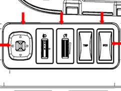
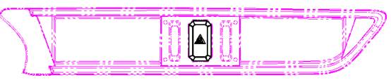
Rearview Mirror Adjustment Switch
Rearview mirror adjustment switch is used to adjust the angle of left, right rearview mirror based on driver’s needs. Turn the middle shifter of rearview mirror adjustment switch to left, right side, then left, right rearview mirror can be adjusted up, down, left and right.
1. Schematic Diagram of Component

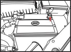
2. Removal and Installation Removal
Use the slotted screwdriver to pry up the left lower side panel.
Disconnect the harness connector on the rearview mirror adjustment switch.
Use the slotted screwdriver to remove the rearview mirror adjustment switch.

Inspection after Installation
![]()
Please check all the switch positions for breakover when the battery is out of work, if not, replace the switch.

![]()
Installation
Install in the reverse order of removal.
Cautions:
Check whether all the keypad functions are normal or not after installation.
If the keypads are not normal or out of work, install or replace them again.
Turning the middle shifting fork of the switch to both side will make the rearview mirror adjustment available. If it stays in the middle part of the switch, the rearview mirror adjustment will not work.
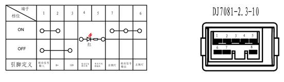
Pin Definition of Rearview Mirror Adjustment Switch:
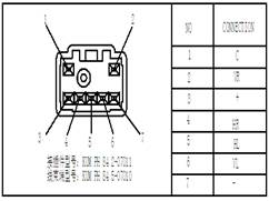
![]()
Breakover Diagram of Gears:
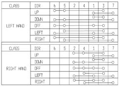
Please check all the switch positions for breakover when the switch adjustment is out of work, if not, replace the switch.
Headlamp adjustment switch can be adjusted by roller wheel from 0 gear to fifth gear, headlamp lamplight height can be adjusted from high to low.
1. Schematic Diagram of Component
2. Removal and Installation
Removal
Remove the driver left lower side bracket;

Pull out the headlamp adjustment switch connectors;
The headlamp adjustment switch is clamped on the left lower bracket, press the clamp block, pull out the switch.
Installation
Install in the reverse order of removal.
3. Connector Terminal Model:

4. Wiring Diagram:

Rotate switch button to adjust backlight luminance of vehicle interior electric
devices.
1. Schematic Diagram of Component

2. Removal and Installation
Removal
Remove
the driver left lower side bracket;
Pull out the dimmer switch connectors;
The dimmer switch is clamped on the left lower bracket, press the clamp block, pull out the switch.
Installation
Install in the reverse order of removal.
3. Connector Terminal Model:

4. Wiring Diagram:

 |
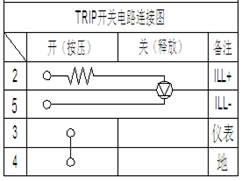
Switch Replacement
1. Removal
Remove the driver left lower side bracket;
② Pull out the TRIP switch connectors;
③ The TRIP switch is clamped on the left lower side guard plate, press the clamp block, pull out the switch.
Inspection after removal
Please check all the switch positions for breakover when the battery is out of work, if not, replace the switch.
2 Installation
Install in the reverse order of removal.
Switch Replacement
1 Removal
Remove the driver left lower side guard plate;
② Pull out the immediate charge switch connector;
③ Immediate charge switch is locked and connected on left downward side guard plate, press locked and connected block, take down switch.
Inspection after removal
Please check all the switch positions for breakover when the battery is out of work, if not, replace the switch.

2 Installation
Install in the reverse order of removal.
Switch replacement
1 Disassemble
① Disassemble the driver's left lower guard plate;
② Unplug the ECO switch connector;
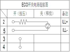
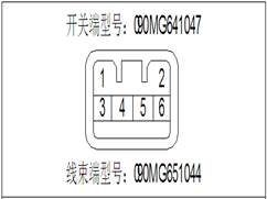
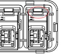
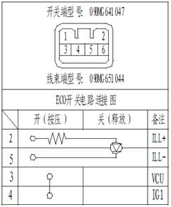
③ The ECO switch card is connected to the lower left guard plate, holding the card connector and taking off the switch.
Check after disassembly
When not working, please check whether the status of each gear is correct. If it is not conductive, replace the switch.
![]()
![]()
![]()
![]()
![]()
2 Installation
Install in reverse order of removal.
EPB Switch(Such as Equipment)
Removal: Take down switch panel, remove switch connector, use cross screwdriver to remove two mounting bolts, then EPB switch can be taken down.

Pin Definition of Switch and Principle of Circuits:


Installation: Install in the reverse order of removal.
AUTOHOLD Switch(Such as Equipment)
Removal: Take down switch panel, remove switch connector, press the plastic snaps between switch and bracket, take down AUTOHOLD switch.

Pin Definition of Switch and Principle of Circuits as shown in the following:
Installation: The bracket inserts switch into mounting hole, press it downward until snap flicks.
Switch Removal: After removing mode switch panel, remove switch connector, press the two snaps between mode switch and switch panel, then take down mode switch.

Definition of Switch Pin
Installation: Insert switch into switch mounting hole directly, press switch downward until snap flicks.
Parking aid switch
Switch Removal: After removing the mode switch panel, remove the switch connector and press the two latches between the parking assist switch and the switch panel to remove the parking assist switch.


![]()
![]()
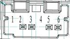
Switch pin definition
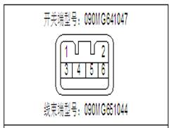
|
Wire harness mating connector model: KET MG651044 |
Pin definition |
Route diagram |
|
|
Pin number |
Pin definition |
|
|
|
1 |
Control loop |
||
|
2 |
ILL(+) |
||
|
3 |
IDN(+) |
||
|
4 |
Control loop |
||
|
5 |
IDN(-) |
||
|
6 |
ILL(-) |
||


Installation: Insert the switch directly into the mounting hole of the switch. Press the switch down until it snaps open.
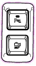
360° panoramic parking switch
Switch Removal: After removing the 360° panoramic parking switch panel, remove the switch connector and press the two card feet between the 360° panoramic parking switch and the switch panel to remove the 360° panoramic parking switch.

![]()
![]()
Switch pin definition

Installation: Insert the switch directly into the mounting hole of the switch. Press the switch down until it snaps open.
Caution lamp switch
Switch Removal: After removing the warning light switch panel, remove the switch connector and press the two clips between the warning light switch and the switch panel to remove the warning light switch.

![]()
![]()
Switch pin definition
![]()
![]()
![]()
![]()
![]()
![]()
![]()
![]()
Installation: Insert the switch directly into the mounting hole of the switch. Press the switch down until it snaps open.
1. Schematic Diagram of Component

2. Removal of Airbag Clock Spring
1) Disconnect the storage battery negative terminal and wait for at least 3 minutes.
2) Remove the driver air bag module, pull out the connectors.

3) Remove the mounting bolts of the steering wheel, pull out the steering wheel.

Cautions:
The mounting bolts is able to be pulled out only when the steering wheel becomes loose, otherwise, the steering wheel may lead to risk or severity of injuries.
4) Disconnect the horn connectors.

5) Pry up the three block pins of the clock spring on the combination switch.
Cautions: The clock spring is able to be pulled out unless the three block pins are pried up completely. The clock spring is easy to be damaged, therefore, be careful when the removal is done.

6) Pull out the clock spring of the air bag.
3. Install clock spring of airbag
Install in the reverse order of removal.
Cautions:
Pull out the SRS clock spring from the package, check the clock spring for damage, check whether the fixed pin is fixed on the component parts or not.
Open the connector gland, plug the SRS harness into the connection hole, then press the gland well.
Before installing the SRS clock spring, make sure that the front wheels stay in the middle direction.(orientation).
Before installing the SRS clock spring, make sure that the clock spring stays in the middle direction (rotate the clock spring to the end clockwise, then rotate 2.5 rounds anticlockwise)
Definition of Clock Spring Connector As Shown In The Following:

 |