![]()
Ⅴ Pipeline and Expansion Valve Assy.
Ⅺ Rear Row Face Mode Air Duct Assy
1 BCM Remote Key Code Learning Guide
1Disassmebly
Ⅻ A/C Control Box Assy. (Electric)
XVII Inner& Outer Circulation Throttle Motor
![]()
![]()
Definitions of "warning", "important note" and "attention"
The diagnostic and maintenance procedures in this manual include general and specific "warnings", "important notices" and "cautions", and JAC is committed to providing maintenance information to assist the after-sales service technician in the diagnosis and maintenance system , so that the vehicle can run normally, but if the technician does not operate as recommended, some programs may pose a risk to the technician.
"WARNING", "IMPORTANT NOTE" and "CAUTION" are prepared to prevent the occurrence of such hazards, but not all hazards are predictable. This information is displayed in prominent positions in the maintenance manual. This information is prepared to prevent the following:
·Causing serious injury to people
·Vehicle damage
·Unnecessary vehicle maintenance
·Unnecessary parts replacement
Improper repair or replacement of vehicle parts
The definition of "warning"
When you encounter a "warning", it asks you to take the necessary action or to prohibit the action taken. If you ignore "warning", you may have the following consequences:
·Causing serious injury to people
If the vehicle is improperly repaired, it will cause serious personal injury to the driver and / or passenger of the vehicle.
The definition of "Important Note”
"Important note" requires special attention to the measures necessary or prohibited. If you ignore the "IMPORTANT NOTE", it will lead to the following consequences:
·Vehicle damage
·Unnecessary vehicle maintenance
·Unnecessary parts replacement
·Abnormal operation or performance of the system or component being repaired
·Damage related systems or components
·Damage fasteners, basic tools or special tools
·Engine coolant, lubricating oil or other essential liquid leakage
The definition of "Attention”
The "CAUTION statement emphasizes the necessity of a diagnostic or maintenance procedure, and the purpose of the "attention" statement is as follows:
Clear procedure
Provide supplementary information for completing a program
Clarify the reason for an operation according to the recommended procedure
Provide information that helps to complete the program in a more efficient way
Provide the technician with past experience information to make the process easier
△Warning To avoid vehicle damage, serious personal injury or even death, when the main part is removed from the vehicle and the vehicle is supported by an elevator, please use jack to support the corresponding vehicle parts to be dismantled.
△ Warning To avoid personal injury when exposed to toxic flamings generated from wipes or electroplating (zinc oxide) metal during grinding / cutting of any type of metal or sheet molding, the working process must be operated in a well-ventilated area and technician should equip permitted respirators, goggles, earplugs, welders gloves and protective clothing.
△ Warning When the technician checks the defective parts, the vehicle should be driven by the assistant. Otherwise, it may cause personal injury.
△ WARNING Before servicing any electrical parts, the ignition key must be in the OFF or LOCK position and all electrical loads must be "OFF"
), Unless otherwise stated in the operating procedure. If the tool or equipment is easily accessible to the exposed live electrical terminals, disconnect the battery negative cable. Violation of these safety instructions may result in personal injury and / or damage to vehicles, vehicle parts.
△ Warning If you repair the airbag, you must disconnect the battery negative at least 90s in order to carry out other operations.
△Warning Please Avoid absorbing A/C refrigerant ,134a(R134a),Lubricating oil steam or fog otherwise it will stimulate the eyes, nose, and pharynx. Operation shall be performed at place with good ventilation
/ When exhausting R134a from A/C system, please use service facilities that meet the standard of SAEJ2210
(R134a recycling facilities) If unexpected fluid leak happens, please ventilate workplace before continuing repair. /
For other information concerning health and safety, please consult manufacturer of refrigerant and lubricating oil for details.
△ Warning please cut the recommended parts only, otherwise it will damage the integrity of the vehicle structure, and may cause personal injury in the event of vehicle collision.
△ Warning If crack appears on the window, yet the window is intact, please use protective glue tape and stamp the tape on the window in crossing type, so as to avoid further damage or personal injury.
△Warning When the driver handle the power window, the function of lifting the window fast may Cause personal injury
△Warning In the course of this procedure, licensed goggles and gloves should be worn to reduce the risk of personal injury.
△ Warning If fire is needed during repair process, the noise-insulating foam material with a distance of 152.4mm within the fire must be cleared. When re-installing foam material, please avoid inhaling smog, or your health will be affected.
△ Warning In the course of processing glass or metal sheet with sharp or rough edge, licensed goggles and gloves should be equipped to reduce the risk of personal injury.
△ Warning high-pressure gas exist inside the bulb. Improper operation may cause bulb’s explosion. To avoid personal injury:
Turn off light switch and cool down the bulb before replacing bulb
Keep the light switch shut down until the bulb has been replaced
Please equip goggles while replacing halogen bulb
While handling bulb, please hold the base part only and avoid contact with glass
The bulb should be kept away from dust and moisture
Please scrap the aged bulb in correct procedures
The halogen bulb should be kept away from children
△ WARNING When working around the running engine, avoid contact with moving parts and hot surfaces to prevent personal injury.
△ WARNING Do not wear goggles and gloves when removing exhaust system parts, otherwise rusting and sharp edges from worn parts of the exhaust system can cause serious personal injury.
△ WARNING To avoid being burned, do not remove the tank cover until the engine is cooled. If the tank and the radiator are not cooled, remove the tank cover, the cooling system will release hot high pressure liquid and steam.
△WARNING Please test vehicle with your safety guaranteed and follow traffic regulations. Do not attempt any operation that may endanger vehicle control. Violation of these safety instructions may result in serious personal injury and vehicle damage.
△Warning When processing fuel, be sure to equip goggles to prevent oil from splashing into the eyes.
△ Warning Airbag system has been equipped on this vehicle. Failure to carry out correct operation procedures may cause following situations:
Unexpected airbag explosion
Pre-tightener spark-off
Person injury
Unnecessary repair of airbag system
△ Warning please obey the following instructions to avoid the situations mentioned above:
Please refer to the overview of airbag system, and confirm whether repairing operations are carried out on airbag system’s parts and circuits.
Please secure the airbag system if you are carrying out repair on airbag system’s parts and circuits.
△ Warning when the airbag is released, the metal surface of airbag system module will be very hot. To avoid fire accident and personal injury:
Make sure the metal surface is fully cooled down for a certain time before touching
Do not put the released airbag system module near any inflammable objects.
△ Warning incorrect assembly of clock spring may cause damage to the inner spiral coil, which will cause failure of coil and airbag module, and lead to potential personal injury.
△ Warning to avoid unexpected release of airbag and personal injury, do not operate the unreleased airbag module as scrapped objects in workplace.
If the sealing container is damaged during scrapping process, some materials in the unreleased module may cause illness or personal injury. /
Please discard the unreleased airbag module by following releasing procedures.
△ Warning while transporting unreleased airbag module:
Do not lift the wire or connector on airbag module
Ensure the airbag’s opening hasn't been put toward you or other people.
△ Warning while storing unreleased airbag module, ensure the airbag's opening is not facing the surface of airbag itself. The opening cannot be faced down, and no object should be put on airbag module. Enough space should be provided for airbag’s unexpected release so as to avoid personal injury.
Do not soak the unreleased airbag module into water or other fluids. Do not place the unreleased airbag module near fire or high-temperature area in case of personal injury caused by airbag’s unexpected release.
△ Warning Do not shake or knock the collision sensor of airbag system. Before charging collision sensor, make sure the sensor has been fixed tightly.failure to obey correct assembly procedures may cause unexpected release of airbag and personal injury.
△ Important notes: do not fix the lifting jack under oil sump, stamping parts or crankshaft belt pulley under any circumstance.
Improper lifting may cause damage to vehicle parts.
△ Important Note: while removing logo / nameplate, please use plastic tool with flat edge to avoid damage on paintwork
△ Important Note: Please use the correct fastener in the correct position. Replace the part number of the fastener must be correct, need to replace the fastener or need to use
Thread locking glue or sealant fasteners are specified in the maintenance procedure, and no paint, lubricating oil or corrosion inhibitor may be used on the fastener or fastener connection surface unless otherwise stated.
These coatings affect the torque and clamping forces of the fasteners and damage the fasteners. When assembling fasteners, be sure to use the correct fastening sequence and tightening torque to avoid damage to parts and systems.
△ Important Note: electrostatic discharge (ESD) will cause damage to solid electric component. Not all components that subject to ESD have been marked with ESD symbol. Therefore, please handle electric components carefully. Please obey the following safety instructions to avoid damage caused by ESD:
-Before repairing electronic component, touch the metallic bonding point and release the static inside body (especially after sliding vehicle seat)
-Do not touch the exposed terminal. The terminal may be connected to circuit which may be damaged by static.
-When repairing connector, do not make tools contact the exposed terminal.
-Do not dismantle parts from protective cap unless otherwise stated.
Avoid following operations unless otherwise stated by diagnostic program:
-Bridging or bonding of components or connectors
-When connecting testing facility’s probes to all parts or connectors, connect binding wire first before using test probes Before opening protective cap of component, please bind the component first. Do not put the solid component on metallic worktable, television, radio or other electric devices.
△ Important note: when connecting/disconnecting battery cable, charger or jumper cable, make sure the ignition switch is at “OFF”. Otherwise the control module or other electric components may be damaged.
△ IMPORTANT NOTE: The inlet and outlet hoses may not be twisted during Installation and may not bend or deform the hose for ease of Installation, as this may cause parts damage.
Parts are damaged.
△ Important note: before diagnosing vehicle, please pay attention to following situations or the control module may be damaged.
-Make sure the software version of tester and terminal are latest
-The vehicle battery must be fully charged and the battery’s voltage should be between 12-14V
The connection of tester and terminal cable should be tight
While programming control module, the charger shouldn’t be connected to battery
△ Important note: the lasting time for steering wheel at its limit position shouldn't exceed 5 seconds, otherwise the steering pump may be damaged.
△ Important Note: do not insert the probe of testing facility (digital multimeter and etc.) into wire connector or the terminal of fuse box. The diameter of testing probe will deform most terminals. Deformed terminals have poor contact, which may cause system failure. Make sure to apply special tool and test terminal from front side. Do not use clip or other substitutes to test the terminal.
△ Important Note: while using special tool to test components, make sure the testing adapter can match to the dimension of terminal. Do not choose adapter by eyeballing, as some terminal’s hole may be bigger than that of actual terminal.
Choose a terminal test adapter, as some connector terminals may appear to have larger holes than the actual terminals in the hole. Using a large terminal test adapter can damage the terminals
△ Important note: to avoid damage on vehicle windows caused by exposed edge, the window must be 1mm lower than the surface of metal sheet to avoid the damage.
1 Items should be checked when operating vehicle
Please press the honk occasionally to ensure the honk is working well. Check all buttons.
While braking, please check whether abnormal noise/sound, increase of brake pedal’s stroke or repetitive lane departure exists. Furthermore, if the brake warning light keeps lighting or flickering, some failures may exist inside brake system.
2 Items should be checked when fuel-charging
Oil/fluid loss of all systems except for windshield washer means the system has failure. Please check and repair system immediately.
Check the liquid level of cleaning agent in liquid reservoir, and add cleaning agent if necessary.
Check the operation of license lamp, headlamp (low/high beam), parking lamp, fog lamp, tail lamp, brake lamp, steering lamp, reversing lamp and hazard warning lamp.
After the vehicle has been parked for a period of time, please check regularly whether water, engine oil, fuel or other fluid exist under the vehicle. Water-dripping is a normal phenomenon when the air conditioning system is used . if fuel leak or smoking is detected, please check reasons and eliminate fault timely.
Apply a layer of silicone grease to the seal with a clean cloth.
Check safety belt system, including the strap, buckle, lock plate, retractor, guide ring and fixing device.
Beware of the crunching sound appeared in vehicle’s rear part. Spare tire, lifting device and tools must be fixed all the times. Please use engine oil to lubricate the ratchet or spiral device of lifting jack after use.
Lubricate key cylinder
Lubricate all hinges on vehicle doors, engine cover, oil filler cap, tail door, plunger latch, glove box and control console. All components of folded seats need to be lubricated.
First, loosen the deposit sediment gathered around vehicle’s sealed area. Then use clean water to rinse vehicle’s bottom. After winter, the vehicle’s bottom should be cleaned once a year at least. Rinsing vehicle’s bottom can remove the corrosive material that can be used for deicing or dust-proof.
Please refer to "Warnings about vehicle lift" in the "Warnings and Precautions".
To avoid personal injury, be sure to use the jack when you are working on a vehicle that is only jack-mounted or under a vehicle. Put the cushion block of rear lifter beneath the junction between the rear frame rail and side frame rail.
△ Attention that the rear lift block can not hit the sill plate to the outside of the frame rails or the floor.
Put the cushion block of front lifter beneath the junction between the rear frame rail and side frame rail.
△ Attention that the rear lift block can not hit the sill plate to the outside of the frame rails or the floor.
|
Application |
Specification |
|
Refrigerant |
480±20g |
Recommended oil/liquid and lubricating oil
|
application |
Oil&liquid / lubricating oil |
|
A/C refrigerant |
R134a |
|
Windshield cleaning agent |
NC310-c |
|
Hinge of engine cover, vehicle door, oil filler cap and tail door |
General lithium-based grease for vehicle |
|
sealing strip for doors and windows |
Silica-based lubricating grease |
2 Regular Maintenance Instructions
The maintenance items given in the maintenance plan has assumed that the vehicle is used for the following purposes:
Passengers and cargo are transported under the constraints indicated by the tire label at the driver's door edge.
Drive on the proper road surface and within the legal limits.
Maintenance items listed in the maintenance items detailed below, in the implementation of the following maintenance items, be sure to replace all parts and make all necessary repairs before they can drive on the road, be sure to use the appropriate fluids and lubricants.
Ⅴ Maintenance Information System
![]()
![]()
![]()
![]()
![]()
![]()
![]()
![]()
![]()
![]()
![]()
![]()
![]()
![]()
![]()
![]()
![]()
![]()
![]()
![]()
![]()


![]()
 1 Arrows and
symbolic description used in the manual
1 Arrows and
symbolic description used in the manual

![]()
![]()
![]()
![]()
![]()
![]()

![]()
![]()
![]()
![]()
![]()
![]() 1 Indicator arrows
1 Indicator arrows
2 Move direction arrow
3 Rotation direction arrow
4 Part number label
5 Partial magnification
Many of the operations related to vehicle maintenance and repair can affect your safety or health issues. Some hazardous operations, materials and equipments and safety rules to avoid hazards have been listed in this session.
This section does not cover all matters related to health and safety, so all operations and procedures and materials should be handled on the premise of safety and health. Before using any product, please check the product manual provided by the manufacturer or supplier.
For example, corrosive sodium carbonate, sulfuric acid.
Used for battery and other materials’ cleaning.
Irritation or erosion for the eyes, skin, smell and throat, and will cause burns to the human body and damage to ordinary protective clothing.
Avoid splashing on eyes, skin and clothing. Wear proper protective clothing, gloves and goggles to prevent inhalation.
Be sure to include flushing equipment nearby, such as eye wash bottles, shower pads, soap, etc., for immediate relief in the event of splashes.
Marked signs of eye danger in a prominent position.
For highly inflammable or explosive materials—please follow no-smoking rules
Air bags are assembled as auxiliary safety system in steering wheel, seats of front passengers, front dashboards and A column, B column and C column.
A high-energy propellant that can generate extremely high-temperature (2500℃ /4532 ℉) gas has been equipped in the air bag expander.
This propellant is sealed in closed components, and will filled into airbag after reacting with airbag. During repair process, do not open airbag, because this will make propellant contact airbag and cause hazard. If air-generator is found broken, please equip full-protective clothing when processing spilled material.
When airbag has been set off normally, please equip safety goggles and gloves during processing. The released air bag should be processed according to relevant laws and regulations in local area. If you have direct contact with ramification of air, please:
Wash contacted part with water
Seek medial assistance if necessary
For your safety, please wear protective equipments before carrying out following operations; when dismantling airbag, make sure the vehicle’s ignition switch is at “LOCK”. Pull up the key and disconnect negative cable, then proceed disassembly process after 90 seconds.
Store the airbag components in straight position
When storing, keep the airbag dry.
When moving airbag components, do not touch electrode and keep airbag away from body.
Place airbag component with protecting cover facing up.
Check whether airbag component is damaged
Disconnect battery’s cathode cable when connecting airbag, and stand in the side of airbag component after waiting 60 seconds.
Rectify and maintain all devices accurately.
Wash hands after processing the released airbag.
Airbag — operations should be avoided
Do not store inflammable material or component together with gas-generator.
Do not soak the unreleased airbag module into water or other fluids.
Do not store gas-generator in area which has a temperature higher than 80 ℃ /176 ℉
Do not store components upside down.
Do not try to open the cover of gas-generator
Do not expose gas-generator to fire or heat source Do not place other object on components’ protective cover
Do not use damaged component
Do not touch the component or gas-generator within 10 minutes after the airbag component is set off Do not use electric probe on the circuit.
Physical contact may lead to frostbite. Please follow the instructions provided by manufacturer. Do not make refrigerant exposed to light, and wear proper goggles and gloves.
If your skin or eyes has contact with refrigerant, use water to rinse the contacted area immediately. Use proper rinsing solution to clean your eyes. Do not rub your eyes and seek medical assistance according to actual situations.
A/C refrigerant — operations should be avoided
Do not store refrigerant in places that are exposed to sun or have heat sources nearby.
When filling refrigerant, do not keep refrigerant bottle straight. Keep the bottle’s valve facing down.
Do not expose refrigerant bottle exposed to frost or snow.
Do not drop refrigerant bottle. Do not release refrigerant into air under any circumstance. Do not blend refrigerant, like mixing R12 (dichlorodifluoromethane) and R134a (tetrafluoroethane)
Before applying binder and sealant, make sure the applied surface should be clean. Please use specified cleaning agent to scrub the applied surface so as to guarantee the binding effect. while applying sealant, do not let the glue solution enter into thread's blind hole, as the glue solution will generate hydraulic locking effect when the fastener is fastening, which will lead to damage on fasteners and/or other components. Furthermore, the glue solution will make fastener unable to acquire correct clamping force during fastening, and deteriorate the sealant's performance. This will cause fasteners unable to fasten correctly, loosen or separate components and cause severe damage to engine or other components.
Hazardous materials exist in binder and sealant, and long-time contact with these material will cause acute/slow disease, occupational disease, skin disease and etc. While gluing, please use venting device to keep the ventilation in workshop; during operation, please wear protective gloves, goggles and clothings. After the process, please wash hands and keep the cleanness and tidiness of workshop.
the waste of wasted glue or solvent’s pollution should be cleaned timely. Long-time accumulation is prohibited. Products should be stored in non-smoking area and keep cleanness while using. Please use applying device or container to proceed working process as far as possible.
When failure or accident happens on vehicle, it may cause vehicle’s deformation, steel plate’s cracking and welding spot’s fall-off. It may cause partial damage to engine, chassis or other assemblies and make binder/sealant’s fall-off and damage. During the repair process, please choose proper binders according to the component’s texture and functions. Some binder/sealants that may be used during repair process have been listed follow for your reference during repair process.
When the interior trim and steel plate of vehicle body are deformed or cracked, the binder will fall off or be broken. Therefore the parts that applied with binder should be fixed during repair process.
Please use knife to clean the binder on vehicle body’s surface, and use alcohol to scrub the remnant binder; please use specific cleaning agent to scrub the glued parts to avoid the existence of remnant glue or other foreign material on applying surface; then apply fixing binder on the original gluing part to glue and seal components.
Some parts (inner trim component, engine, gearbox and etc.) needs to be glued or sealed if suffering damage. While applying sealant, please clean the binding surface so as to avoid the negative effect of rag and crack.
The binder/sealant can prevent water and dust from entering into vehicle, and is corrosion-resistant The original sealing joints are apparent. If these joints are broken, they need to be re-sealed. Please use binder/sealant with high-viscosity while sealing the openings and joints. Please follow the instructions of the chosen materials
-While applying binder/sealant, precautionary measures must be taken to prevent binder/sealant from entering into components’ opening (door lock, glass-lifting groove, glass regulator and safety belt’s retractor) or other moving, rotary components, especially parking brake’s drawing. After applying binder/sealant, make sure all release holes of vehicle are open.
-When processing, please wear specific protective goggles and gloves to prevent personal injury.
-When vehicle leaves factory and all metal sheets of vehicle have been coated, repaired and replaced with new spare parts, please apply rust-proof base coat on the surface of exposed metal before gluing.
-After gluing, some binder/sealants need to be dried and solidified. The baking condition is (70-80)℃,20-30min.
Inhaling asbestos dust will cause damage to lung and lead to cancer. Please moisten asbestos while processing waste materials, and place it in sealed container with apparent mark for safe processing. /
If it’s necessary to cut or drill on asbestos material, please moisten the material first, and use manual or low-speed power tools only.
The released gas during charging is explosive, therefore do not carry out firing process near battery that is charging or has been charged sometime ago. Proper ventilation must be guaranteed.
Chemical materials such as solvents, sealants, adhesives, coatings, resin foams, battery acid, engine coolant, brake fluids, fuels, lubricants and greases should be used very much note. They can be poisonous, harmful, aggressive, irritating or highly flammable, with highly dangerous odors and dusts.
The effects of long-term overexposure to a chemical environment may be immediate or chronic, transient or permanent, cumulative, superficial, life-threatening or may affect lifespan.
Carefully read and follow the warnings and cautions on the container of origin and any accompanying flyers, posters or other instructions for use, as well as the health and safety information sheets for the ingredients, which are obtainable by the manufacturer.
After getting physical contact with chemical materials, remove it from the skin and clothing as soon as possible, and immediately replace the heavily immersed clothing and thoroughly clean it.
Strictly follow the work instructions and wear protective clothing to avoid direct contact with the skin and eyes.
It must be cleaned before handling breaks, eating, smoking, or using the washroom while handling chemical materials.
Keep working areas clean, tidy and do not spill chemicals.
Unless specified by the manufacturer, chemical materials can not be mixed at will; some chemicals can form other toxic or harmful chemicals that can release other toxic and harmful gases when mixed and can cause explosions and other accidents.
Do not spray chemical materials in a closed environment.
Unless instructed by the manufacturer, chemical materials should not be heated as some chemicals are highly flammable while others may emit toxic and noxious gases.
Do not allow the chemical container to remain open and the emitted gas may accumulate to a toxic, hazardous or explosive level. Some gases are heavier than air and accumulate in confined spaces.
Chemicals can not be loaded into unlabeled containers.
Do not use chemicals to clean hands and clothing. Chemicals, especially solvents and fuels, can dry the skin, cause allergies, cause inflammation of the skin or directly absorb toxic and harmful substances through the skin, which can affect your health.
Unless the container has been cleaned under supervision, otherwise do not use empty containers for storing other chemical materials.
Do not smell chemical materials at will Short-term exposure to high concentrations of gas may still lead to poisoning or injury
Powder, dust, and dust may be irritating, harmful or toxic. Avoid inhalation of powdered chemicals and dust raised by dry rubbing operations. Wear respiratory mask guards to prevent inhalation of dust if ventilation is poor.
Fine dust of combustible material may cause the danger of explosion and avoid explosion and sources of ignition.
Failure to use the electrical equipment correctly or abuse the equipment in good condition may result in electric shock.
Be sure to maintain the electrical equipment within the specified time and regular testing. Faulty equipment should be marked and preferably moved outside the work area.
Do not expose the wires, cables, plugs and jacks to wear, kinks, cuts, cracks, or other damage. Do not allow electrical equipment and wires to contact with water.
Ensure that the electrical equipment is protected by the correct fuse.
Misuse of electrical equipment is prohibited, and do not not use any device with hidden trouble, because the result may affect personal safety.
Ensure that the cable for mobile electrical equipment will not be pinched and damaged.
Basic first-aid training must be performed on specialized electrical operators.
In the event of an electric shock:
Turn off the power before touching the victim.
If you can not turn off the power, use dry insulator material to remove the victim's power.
If you have specialized emergency training, carry out on-site first aid immediately.
Request medical assistance.
Exhaust gas contains toxic and harmful chemicals such as carbon oxides, nitrogen oxides, acetaldehyde, lead and aromatic hydrocarbons. The engine can only be operated with suitable exhaust ventilation or general ventilation and with open space.
Used to isolate noise and sound.
The fibrous surface and sharp edges can cause skin irritation or scratch.
During operation, the instructions of the operating procedures and gloves should be worn to avoid excessive skin contact with the fibers.
Many materials related to vehicle maintenance are extremely flammable. Some materials are toxic and harmful when they are burned.
Please follow fire safety practices when storing and disposing flammable materials or solvents, especially near electrical equipment or near welding areas.
Before using electrical and welding equipment, please make sure that there is no risk of fire
When welding or using heating equipment, prepare a fire extinguisher around the work area.
Well-trained first-aid personnels should be in the workplace in order to comply with the law.
If eyes are splashed, rinse with water for at least 10 minutes.
If the skin is contaminated, wash the contaminated area with soap and water.
If suffering frostbite, the area affected by frostbite should be immersed in ice or cold water.
Inhalation of toxic gases should be promptly transferred to fresh air. If adverse reactions persist, they should be taken to the hospital for medical attention immediately.
If you inadvertently mistakenly suck the liquid, you should inform the physician of the information marked on the container or label, unless the instructions on the label, or not blindly guide.
Cured foam is a cushion for seating and decoration.
Follow the manufacturer's instructions.
Components that haven’t been chemically effected are irritating and may be harmful to the skin and eyes. Wear gloves and goggles during operation.
Persons with chronic respiratory diseases, asthma, bronchial problems, or those with genetic allergies should not handle or approach uncured material.
Their spare parts, vapors or sprays will cause immediate irritation and allergic reactions and can be toxic and harmful.
Remember not to breathe vapor or spray, these materials must be used in a well-ventilated and breathable protected. Do not remove the mask immediately after spraying.
Wait for vapor to completely dissipate before removing.
The uncured components and the matured foam are burned to produce toxic and harmful gases. During the foam operation, unless the vapor or spray has been completely removed, no smoking, no open flame, no electrical equipment, no foam, or special thermal cutting of foams should be done in a well-ventilated environment.
Minimize direct skin contact with the fuel. If exposed, wash the contacted area with soap and water immediately.
Extremely flammable - follow no-smoking regulations.
Accidental swallowing can cause mouth and throat irritation, and stomach absorption can lead to generalized weakness and confusion. A small amount of gasoline can affect a child's life and safety.
Therefore, it is very dangerous if the liquid enters lungs.
Gasoline will cause dry skin. Long-time or frequent contact will cause skin allergies and dermatitis. The fuel can cause severe pain if entering into eyes.
Motor gasoline may contain a large amount of benzene, which can cause poisoning if inhaled. Therefore the concentration of gasoline vapor must be kept low, as high concentrations of gasoline vapor can cause
Stimulation of the eyes, nose and throat, nausea, headache, frustration and drunken physical discomfort. Extreme concentrations of gasoline vapors can lead to rapid loss of consciousness.
In the treatment of gasoline, it is necessary to maintain good ventilation, special attention to the operation in a confined space to avoid the risk of inhalation of gasoline vapor due to splashing.
Special attention should be paid when cleaning and maintaining gasoline storage equipment.
Gasoline can not be used as a detergent, and do not suck gasoline with mouth.
It is important that you always keep all your tools and equipment in good working condition and that you are working correctly. Remember that tools or equipment should not be used in ways that are contrary to their intended function. Equipment such as cranes, jacks, axles and chassis supports or slings
shall not be subjected to loads exceeding the maximum limit they can bear. Damage caused by overload does not necessarily appear immediately, yet may cause serious accidents the next time.
/
Do not use tools or equipment that has been damaged or is in poor working conditions, especially some high-speed equipment such as grinding wheels. Damaged grinding wheel will break without warning and cause serious injury.
Wear appropriate eye protection when using grinding wheel, chisel or sand blasting equipment. Appropriate breathing masks must be equipped when using sand-blasting equipment, handling asbestos-containing materials, or using spray equipment. There must be ventilation device to control the amount of dust, mist and fumes in the environment.
Avoid long-term exposure to mineral oil, all the lubricating oil and grease, which can irritate eyes and skin.
-Wear protective clothing, including impervious gloves.
-Do not wear highly engine oil-contaminated clothing and footwear. Uniform must be regularly cleaned and kept clean.
-Emergency treatment of open wounds should be promptly available.
-During working, try to apply the insulation cream on the skin, so as to avoid direct skin contact with the engine oil.
-Remove all engine oil by washing with soap and water. Apply a lanolin-containing protective agent that will help replace the natural oils that are removed from the skin.
If skin lesions occur, go to hospitals immediately for medical assistance.
-Before working, remove the residual grease on components as far as possible.
Goggles, such as chemical goggles or face shields, should be worn if possible in direct contact with the eyes; in addition, eye-wash equipment should be provided.
Used waste engine oil and oil filters should be recycled through authorized or licensed waste disposal dealers or waste engine oil recyclers. If you have any questions, you should promptly contact the relevant departments of the local competent authorities for disposal.
It is against the law to dump used engine oil directly into the ground, sewer or drain or water pipes.
Extremely decibel-level noise can occur while performing certain operations that can cause hearing damage. At this time, proper hearing protection should be equipped.
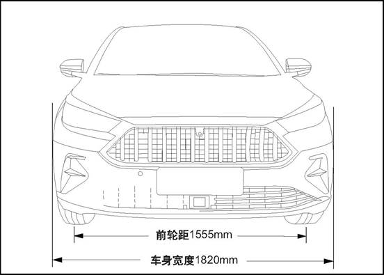
Front view
Front tread 15555 mm Bodywork width 1820 mm
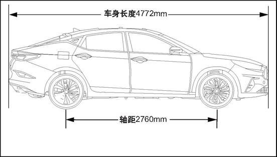
Side view
Wheelbase 2760 mm Vehicle length 4772mm
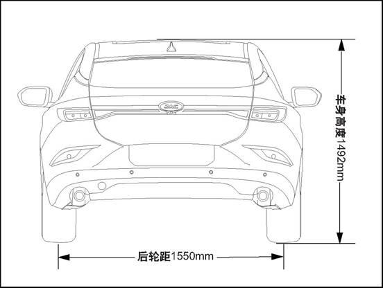
Rear view
Rear tread 1550 mm![]()
|
Item |
Value |
Unit |
|
Total length |
4772 |
mm |
|
Total width |
1820 |
mm |
|
Total height (empty load) |
1492 |
mm |
|
Wheelbase |
2760 |
mm |
|
Front tread |
1555 |
mm |
|
Rear tread |
1550 |
mm |
|
Item |
1.5T+6MT |
1.5T+CVT |
Unit |
|
Passengers |
5 |
5 |
Person |
|
Curb weight |
1432 |
1440 |
kg |
|
Total weight |
1857 |
1865 |
kg |
|
Front axle’s load |
967 |
977 |
kg |
|
Rear axle’s load |
890 |
888 |
kg |
1 Vehicle Identification Number
Vehicle VIN is a legal identifier.
Vehicle identification number (VIN) position
There are several vehicle identification codes on the vehicle,and the following 10 are the most common:
1. Located on the instrument table at the lower left corner of the windshield, visible through the windshield.
2. Under the front passenger seat.
3. In the vehicle glove box.
4. On the engine cover.
5. On the front side of right-front door inner panel
6. Lower side of left B-column
7. On the front of the left front door inner plate
8. On the upper side of tailgate inner panel
9. Refer to ECU data.
10.Refer to MP5 data.
1 Diagnostic information and procedures
Wind noise / air sound
△CAUTION When the technician checks the faulty location, the assistant should drive the vehicle. Otherwise, it may cause injuries.
You must test the car in the car, in order to accurately confirm the location of the wind noise. In general, wind noise has major and minor leaks. If all leaks are not repaired during the repair, wind noise can only be reduced and wind noise can not be completely eliminated. Test-drive maintenance staff must bring the following tools to help diagnose the specific location of wind noise:
Stethoscope
Masking tape
Stitch seam
Marker pen
Follow the procedure below to try the road:
Select a line, with east, south, west and north four different directions of the straight street.
Choose less traffic or less noise in the street, to avoid affecting the test.
The road test is conducted at the speed at which the customer believes the noise is most pronounced or noisy, and a speed limit of more than the legal limit is strictly prohibited. The wind noise emitted under the following conditions is external wind noise:
Wind noise can be heard immediately while driving down the window glass.
When the tape is attached to the various decorative seals and gaps, the wind noise disappears immediately. Internal wind noise is caused by air escaping from the vehicle and should be repaired as follows:
In determining the location of the leak, attach the tape to the body lock pillar relief valve. The air pressure will be formed immediately inside the car, and the wind noise will be enhanced.
Use a stethoscope to confirm the leak location.
Use masking tape to temporarily repair leaks.
Continue road test to confirm whether the wind noise is completely eliminated or other leaked parts.
After confirming all leaks by road test, return to the repair shop and make permanent repairs with professional and reasonable positioning methods and sealing materials.
Please check the following table for common abnormal noise and solutions:
|
No. |
Symptom |
Parts for check |
Solution |
|
1 |
The vehicle generates squeaky sound when the engine speed is high. |
Check whether insulation panel contacts vehicle’s bottom part |
Lift the vehicle and perform a visual inspection |
|
Bend the insulation panel slightly to create a gap between it and the bottom of the vehicle body. |
|||
|
2 |
The front of the vehicle squeaks when the weather is cold |
Check the balance bar isolation rubber sleeve |
Cold Road Test vehicle and pass the bumpy road, so that the front suspension can reach maximum travel. |
|
Remove the isolation rubber sleeve and tape the front stabilizer bar, reinstall the isolation rubber sleeve on the tape. |
|||
|
3 |
Bumpy rear bass issued by the boring abnormal sound |
Check if the spare tire in the luggage compartment is properly secured |
Open the luggage compartment and inspect the spare tire and driver's tools. |
|
Refit spare tires and truck tools. |
|||
|
Test vehicle to check whether abnormal sound has been eliminated. |
|||
|
4 |
The rear of the vehicle emits a glass percussion while traveling on a bumpy road |
Check the rear door lock is not properly adjusted |
Carry out road test to check this situation. |
|
Loosen the lock nut and adjust the lock. |
|||
|
5 |
The door squeaked |
Check if the harness connector inside the door trim panel creaks |
Tap the trim plate and carefully observe if you hear a squawk |
|
Remove the door trim and wrap the foam padding around the harness connector according to the actual vehicle conditions. |
|||
|
6 |
Squeaking when using the door |
Check door hinges for lack of lubrication. |
Push the door back and forth and listen carefully to check whether the door squeaks. |
|
Use rust inhibitor to lubricate the door hinge and apply grease. |
External wind noise
Repair methods of wind noise leak and water leakage are very close. The actual repair procedure depends on the type of sealing components being repaired.
Repair of abnormal sound
Abnormal sound comes mainly from the relative motion that should not exist between the vehicle parts. There are three ways to repair abnormal sound:
Firmly tighten the parts so that there is no relative movement of the vehicle during driving.
Separate parts so that parts do not come into contact with them at work.
Isolate parts so that there is no abnormal noise when parts move. A uniform surface with low-friction can be used to eliminate sticking slip between parts.
If you want to buy special tool, please contact 4S shop in each area of JAC. For contact information, please contact 4008889933.
|
No. |
Diagnosis device type |
Diagnosis device version |
Tool No. |
|
1 |
3G-X431 |
V11.70 |
JAC-T1Z002 |
1 Generator Assembly
2 Starter
3 Battery Tray
4 Battery Assembly
5 Battery Heat Shield
6 Left Front Door Lock Cylinder
Starting system is mainly made up of battery, ignition switch, starter, starting relay and related wire harness. As the main part of starting system, starter is consisted of direct current motor, solenoid switch and transmission mechanism. Direct-current motor introduces the current of the battery and rotate the drive gear of the starter;
The drive mechanism meshes the drive gear into the flywheel gear ring and can automatically come away after the starting of the starter; the connection of the starter wire harness is
controlled by a solenoid switch.
Charging system main parts contain: generator assembly( with voltage regulator inner), battery and battery charging indicator lamp.
The main function of the generator is to provide the electricity to all the electric appliances (beside the starter), and charge the battery when the generator works normally.
The generator is mainly made up of five parts:rotor, stator, voltage regulator, housing and end cover. Its rotor and stator use the principle of electromagnetic cutting to produce the electricity,
the produced alternating current is transfered into the stable direct current through the rectification and the voltage stabilization of the voltage regulator. Generator is driven by the engine through the engine belt and gear device.
The car uses maintenance-free batteries, the difference with the traditional battery is the battery cover without vent plug; except for the battery on both sides of the small vent outside, the battery is completely sealed. Ventilation holes can make a small amount of gas generated by the battery discharge, the battery electrolyte within the chemical reaction will produce a small amount of gas, if you do not set the exhaust hole, the battery internal pressure increases with the gas increases, when over the battery shell body limit, the shell will rupture.
Compared to the traditional battery, this battery has the following advantages:
No water need to be added with the use cycle.
Over-charge protection.
Not easy to leak electricity as the traditional battery.
Smaller weight and volume and bigger capacity.
In the whole electric system, the battery has three main functions:
Providing the starting power for the engine when start the vehicle.
Acting as the voltage stabilizer of the electric system.
When the generated electricity from the generator can not satisfy the need of the electric system, the battery can provide the electricity in a certain period.
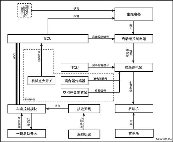
The body control module (PEPS controller is integrated into the body control module) checks whether the key is available by sending low-frequency signals. If the key is available, the key will send out a radio frequency response, and the receiving antenna will send the signal to the body control module. The body control module receives the start signal from button-start switch, and the body control module and ECU will Verify whether the starting conditions are met. If so, ECU controls the main relay to provide power to the start control relay. At the same time, the start control relay receives the start control signal from ECU, and the start control relay controls the start relay to work. At the same time, TCU gives the start relay a start signal, and the start relay starts to work. The electromagnetic switch of the starting motor is closed after being powered on, providing a closed circuit between the battery and the starting motor. The starting motor is grounded through the engine cylinder block. When the two conditions of power supply and grounding are met, the starting motor runs and the engine starts.
The manual transmission vehicle ECU receives the start signal of the mechanical ignition switch, ECU controls the main relay to provide power to the start control relay, at the same time, the start control relay receives the start control signal from ECU, the start control relay controls the start relay to work, and the start relay receives the transmission from clutch sensor and neutral switch signal, start the relay to work, thus driving the starter.
Button-start
Switch Start
control signal Start
control signal Main relay Power
Supply MT Model Signal Neutral
position sensor Neutral
position signal Clutch
signal Control Mechanical
ignition switch Clutch
sensor Antenna Body control module C4 Remote
control keys Battery Starter Starting relay Starting
control relay Starting control relay
![]()
![]()
![]()
![]()
![]()
![]()
![]()
![]()
|
No. |
fastener name |
torque(N·m) |
|
1 |
Battery tray fixing bolt |
- |
|
2 |
Battery pressing plate nut |
- |
Before repairing any electric part, the power supply mode of the start switch should in the OFF state, and all the electric loading must be OFF(closed), except the operation procedures has other explanation. If the tool or equipment is easily accessible to the exposed live electrical terminals, disconnect the battery negative cable. Violation of these safety instructions may result in personal injury or damage to vehicle parts.
Use the assist battery to ignite
1). If you need to use the auxiliary battery and jumper to start the engine, be sure to use 12V auxiliary battery. After connecting the battery jumper wire,
make sure that the jumper wire is clamped to the battery terminal and has good contact.
Prevent battery from over-discharge method
1) Always keep the battery surface (especially the top) clean and dry, the connection part of the port should be clean and tightened, if the car is not used for a long time,
should disconnect the battery negative terminal and regularly check the battery charging status.
a.Check if there are any after-sales retrofit devices that will affect start-up, charging or ignition system operation.
b.check accessible and viewable parts to check if there are obviously damaged parts or conditions that may cause possible fault.
c.Check the battery is installed correctly.
d.Test the state of the battery, the battery voltage shall not be less than 10.5V.
e.Check the relevant wire is damaged, check the starter motor, starter solenoid switch, starter switch, battery and all related ground connection is reliable.
f.Check generator installation is loose or improper installation, and transmission belt preload is normal, there is the possibility of skidding.
|
No. |
Fault symptoms |
Fault analysis |
Solutions |
Remark |
|
1 |
Engine cannot be started |
Ignition and fuel system faults |
Check the ignition and fuel system |
|
|
Starter power supply faults |
Check starter power supply |
|||
|
Starter faults |
Replace the starter |
|||
|
Starter solenoid switch faults |
Replace the starter solenoid switch |
|||
|
Engine mechanical binding |
Check the engine running related mechanical parts |
|||
|
Starter solenoid switch power supply wire harness faults |
Check relative wiring |
|||
|
Starter grounding faults |
Check the ground connecting wiring |
|||
|
Starter control power supply wire harness faults |
Check relative wiring |
|||
|
Starter relay fault |
Replace the starter relay |
|||
|
Ignition switch fault |
Replace the ignition switch |
|||
|
2 |
Engine can not stop working |
Starter relay fault |
Replace the starter relay |
|
|
Starter faults |
Replace the starter |
|||
|
Ignition switch fault |
Replace the ignition switch |
|||
|
3 |
Starter noise |
Flywheel gear ring broken(gearwheel craze, gearwheel lost, gearwheel wear and so on) |
Replace the flywheel gear ring. |
|
|
Flywheel broken(flywheel deformation) |
Replace the flywheel |
|||
|
Starter fault(gear craze or wear, shaft sleeve wear) |
Replace the starter |
|||
|
4 |
Charging indicator lamp always on |
Generator to ECU circuit loop |
Check relative wiring |
|
|
Generator power supply wire harness default |
Check relative wiring |
|||
|
Generator default |
Replace the generator |
|||
|
5 |
Charging indicator lamp can not light on |
Generator default |
Replace the generator |
|
|
6 |
Generator noise |
Generator default |
Replace the generator |
|
|
Generator installation fault |
Re-installation |
|||
|
Generator belt fault |
Re-installation or replacement |
|
Steps |
Inspection content |
Solution |
Decision specification |
Next step |
|
|
Yes |
No |
||||
|
1 |
Confirm the fault phenomenon |
Set the ignition switch on ST position, start the engine. |
Confirm if the engine rotates |
Next step |
Turn to step 4 |
|
2 |
Confirm the rotation situation of the engine |
Set the ignition switch on ST position, start the engine; read the engine rotation speed according to the instrument speed meter or diagnosis data. |
whether the engine rotation speed reaches the starting rotation speed. |
Check the engine ignition system and fuel supply system. |
Next step |
|
3 |
Check the battery voltage |
Set the ignition switch on ST position, start the engine, measure the battery voltage. |
Standard voltage value: larger than 10.5V |
Replace the starter |
Check the charging system |
|
4 |
Check the starter electromagnetic switch motion |
Set the ignition switch on ST position, start the engine to check the starter electromagnetic switch motion |
whether the starter electromagnetic switch works |
Next step |
Turn to step 8 |
|
5 |
Check the engine mechanical running |
Check the engine and belt drive system mechanical clamping stagnation(engine clamping stagnation, generator clamping stagnation) situation |
If it has clamping stagnation |
Repair the clamping stagnation part |
Next step |
|
6 |
Check resistance between the starter and the power supply |
Measure the circuit resistance between the battery and the starter motor. |
Standard value: <1Ω |
Next step |
Check and repair the cable |
|
7 |
Check the starter electromagnetic switch wire harness. |
Check if the starter electromagnetic switch wire harness has looseness, corrosion and damage. |
If the wiring connection is normal or not? |
Next step |
Check and repair the cable |
|
8 |
Check the starter control power supply voltage. |
Set the ignition switch on ST position, measure the voltage of starter wiring connector terminal. |
Standard voltage value: 11V ~ 14V |
Replace the starter |
Next step |
|
9 |
Check the starter control power supply wire harness resistance |
Measure the voltage value between the starter relay ER03 terminal 87 and starter wiring connector B08 terminal 1. |
Standard value: <1Ω |
Next step |
Check and repair the cable |
|
10 |
Check the starter relay motion |
Set the ignition switch on ST position, check the starter relay motion. |
If the starter relay actuates |
Next step |
Turn to step 14 |
|
11 |
Check the starter relay fuse SF10. |
Check the starter relay fuse SF10. |
Check if the fuse is blown |
Repair the wiring short circuit fault or replace the fuse. |
Next step |
|
12 |
Check the starter relay loading power supply voltage. |
Set the ignition switch on ST position, measure the starter relay ER03 terminal 30 power supply voltage. |
Standard voltage value: 11V ~ 14V |
Next step |
Check and repair the wiring. |
|
13 |
Check the starter relay fuse SF10 power supply circuit. |
Measure the wiring resistance between the starter relay fuse and battery. |
Standard value: <1Ω |
Next step |
Check and repair the wiring. |
|
14 |
Check the control wire voltage of the starter relay. |
Set the ignition switch on ST position, measure the starter relay terminal 85 voltage. |
Standard voltage value: 11V ~ 14V |
Next step |
Turn to step 16 |
|
15 |
Check the control wire ground of the starter relay. |
Measure the voltage value between the starter relay terminal 86 and grounding point E08. |
Standard value: <1Ω |
Next step |
Check and repair the wiring. |
|
16 |
Check ECU ignition signal. |
Set the ignition switch on ST position, measure ECU E19 terminal 45 power supply voltage. |
Standard voltage value: 11V ~ 14V |
Replace the ECU, the system is normal. |
Next step |
|
17 |
Normal system |
|
|
|
|
1. Open the engine cover
b. Disconnect the negative and positive cable of the battery with reference to the disconnection and connection of the battery cable
c. Remove the battery pack See Battery pack
d. Remove Battery assembly
![]() 1) Remove battery heat heat shield
1) Remove battery heat heat shield
2) Separate battery assembly and battery heat shield.
Check if the battery cable clamp is damaged. Replace any battery cable damaged or deformed by the cable clamp.
Check the battery chassis and battery holder hardware for damage. Replace any damaged parts.
Check the battery case for cracks or other damage that may cause electrolyte leakage. In addition, check whether the battery terminals are loose. Replace any damaged parts.
![]() Installation of Battery assembly
Installation of Battery assembly
a. Install the battery heat shield cover to the outside of battery assembly.
b. Install battery heat heat shield
c. Install Battery pressure plate
d. Connect the battery negative cable.
e. Close the engine compartment cover
1. Open the engine cover
2. Disconnect the negative harness of the battery refer to the disconnection and connection of the battery
c. Remove the battery pack See Battery pack
d. Remove the battery tray assembly See Battery assembly
e. Remove the battery tray assembly
![]() 1)Disconnect the engine control
module harness connector 1.
1)Disconnect the engine control
module harness connector 1.
2) dismantle the 4 fixing bolts of engine control module and take off the engine control module.
![]() 3). Remove the 4 bolts that fix the
battery tray assembly.
3). Remove the 4 bolts that fix the
battery tray assembly.
4) Take down the battery tray assembly.
a. Install the battery tray assembly
![]() 1). Install the 4 bolts that secure
the battery tray bracket assembly.
1). Install the 4 bolts that secure
the battery tray bracket assembly.
![]() 2) Mount the 4 fixing bolts of
engine control module and take off the engine control module.
2) Mount the 4 fixing bolts of
engine control module and take off the engine control module.
3)Connect the engine control module harness connector 1
b. Install battery assembly.
c. Install battery keep plate
d. Connect the battery negative cable.
e. Close the engine compartment cover.
1. Open the engine cover
![]() 2. Dismantle battery keep plate assembly.
2. Dismantle battery keep plate assembly.
1) Remove the 2 nuts fixing battery keep plate assembly.
![]()
![]() 2)
Take out battery keep plate assembly.
2)
Take out battery keep plate assembly.
![]() Install battery keep plate
Install battery keep plate
1) Install battery keep plate.
2) mount the 2 nuts fixing battery keep plate assembly.
![]()
![]() 2.
Close the engine cover
2.
Close the engine cover
1. Make sure the ignition is off
2. Open the engine cover
3. Disconnect the battery negative cable.
![]() 1) Disconnect the battery negative
cable nut
1) Disconnect the battery negative
cable nut
2) Remove the battery negative cable from the battery.
![]()
![]() 4 Disconnect the negative port of
the battery
4 Disconnect the negative port of
the battery
1) Open the battery positive electrode protection cover.
![]() 2) Loosen the battery positive electrode nut.
2) Loosen the battery positive electrode nut.
3) Remove the battery positive cable from the battery.
![]() 1. Connect the battery positive cable.
1. Connect the battery positive cable.
1) Connect the battery positive cable.
2) Tighten the battery positive cable nut.
3) Install the battery positive electrode protection cover.
![]() 2. Connect the battery negative cable.
2. Connect the battery negative cable.
1) Connect the battery negative cable.
2) Tighten the battery negative cable nut.
![]()
![]() 3.
Close the engine cover
3.
Close the engine cover
1. Remove the key gear piece
![]() 1). Press the button on the key,
and pull out the key tooth piece upward.
1). Press the button on the key,
and pull out the key tooth piece upward.
1. Install the key tooth piece
![]() 1). Insert the key tooth piece into
the key.
1). Insert the key tooth piece into
the key.
1. Open the left front door
2. Remove the left front door cylinder
![]() 1) Open the rubber cover 1
1) Open the rubber cover 1
2) Insert the mechanical key into the removal port of the lock cylinder cover, and pry down the left front door lock cylinder cover 2
![]() 3) Remove the left front door lock
cylinder fixing bolt.
3) Remove the left front door lock
cylinder fixing bolt.
![]() 4) Use a tool to pry down the left
front door cylinder.
4) Use a tool to pry down the left
front door cylinder.
1. Install left front door lock cylinder
![]() 1) Put the left front door lock
cylinder at the installation position
1) Put the left front door lock
cylinder at the installation position
△Attention: Keep the left front door cylinder clean.
![]() 2)Install the one left front door
lock cylinder fixing bolt.
2)Install the one left front door
lock cylinder fixing bolt.
![]() 3) Install the left front door lock
cylinder cover 2
3) Install the left front door lock
cylinder cover 2
4) install the rubber cover 1
2. Close the left front door
1. Open the engine cover
2. Disconnect the battery negative cable.
3 dismantle generator assembly
1) Remove the drive belt
2) Disconnect generator assembly wire harness connector 1.
3) Remove the charging cable fixing nut 2 of generator assembly and take off the charging cable.
![]() 4) Remove the two fixing bolts 3 of
the generator.
4) Remove the two fixing bolts 3 of
the generator.
5) Remove generator assembly
1 install generator assembly
1) Put generator assembly at the installation position
2) Install the 2 bolts 3 that fix the generator assembly.
3) Mount the charging cable fixing nut 2 of generator assembly and tighten it.
![]() 4) Connect generator assembly wire
harness connector 1.
4) Connect generator assembly wire
harness connector 1.
5) Install the drive belt.
2). Connect the battery negative cable.
3. Close the engine compartment cover
1. Open the engine cover
2. Disconnect the battery negative cable.
3. Dismantle the starter
![]() 1)Disconnect the starter control
wire harness connector 1.
1)Disconnect the starter control
wire harness connector 1.
2) Remove fixing nut 2 of power cord.
![]() 3) Remove the 2 fixing bolts of
starter
3) Remove the 2 fixing bolts of
starter
4) Take down the starter.
1 Install starter
![]() 1) Put the starter at the
installation position
1) Put the starter at the
installation position
2) install and tighten the 2 fixing bolts of starter
![]() 3) Mount the fixing nut 2 of starter power cord.
3) Mount the fixing nut 2 of starter power cord.
4) Connect the starter control wire harness connector 1.
2). Connect the battery negative cable.
3. Close the engine compartment cover
1. Front Low Frequency Antenna
2. Button Type Ignition Switch
3. Electronic Steering Column Lock
4. Standby Antenna
5. Door handle Low Frequency Antenna
6. Middle Low Frequency Antenna
7. Rear Low Frequency Antenna
8. Anti-theft Induction Coil
Passive Entry & Passive Start (PEPS) means a keyless entry and keyless start system that uses state-of-the-art RFID radio frequency technology and a vehicle identification code recognition system to provide a comfortable and completely new driving experience with user-friendly convenience.
PEPS system includes: PEPS controller (integrated in BCM), intelligent key (ID), Button start switch, vehicle low-frequency antenna (LF), standby antenna, door handle antenna (HSU), electronic steering column lock (ESCL), etc.
|
Part Name |
Instructions |
|
PEPS controller |
PEPS controller is the heart of the PEPS system and is responsible for interacting with other system information and performing related actions. Meanwhile, the PEPS controller is also the power management system, which is responsible for the power state management of the whole vehicle. The ACC and ON power sources of the whole vehicle are all from PEPS. |
|
Smart key |
Smart key: is a PEPS system tool for computer-human interaction (1) The low-frequency interaction between the low-frequency antenna of the door handle and the low-frequency antenna of the rear guard and the PEPS controller is carried out. At the same time, the identity of the key is confirmed through the high-frequency to realize keyless entry into the vehicle; (2) Conduct low-frequency interaction with the PEPS controller through the low-frequency antenna in the car to confirm the location and legitimacy of the key, and confirm the identity of the key through the high-frequency to prepare for keyless startup. |
|
Button-start Switch |
Button-start switch is the tool for human-machine interaction of PEPS system, customer sends power switching to PEPS system though the button, engine starting or closed request. |
|
Vehicle low-frequency antenna |
The low-frequency antenna in the vehicle is the vehicle low-frequency signal transmitting tool of the PEPS system. |
|
Standby antenna |
The spare antenna is used to place the key beside the smart key when there is no power to carry out passive near-field low-frequency communication and achieve the purpose of key authentication. Standby antenna is also required for off-line matching. |
|
Door handle antenna |
The door handle antenna is used to generate low-frequency signal when the user presses the door handle button to search for the smart key within the signal range, so as to achieve the goal of key identity authentication. |
|
Electronic steering column lock (ESCL) |
The function of electronic steering column lock is similar to the common ignition lock function, after the vehicle stops to lock the vehicle steering string, improve the performance of vehicle anti-theft prevention. |
PEPS and ESC: PEPS acquires CAN network vehicle speed signal from ESC to determine whether the vehicle is still or running.
PEPS and EMS: PEPS obtains clutch state, neutral position, engine speed, engine running state, engine start&stop working state, anti-theft authentication request signal from EMS, realizes anti-theft function, start&stop function, etc.
PEPS and ICM: The information between PEPS and ICM is exchanged, and the alarm prompt information is exchanged and displayed.
PEPS and BCM: PEPS interacts with BCM to realize the opening and closing of door locks and the lifting of windows and doors. Also, BCM is the gateway, transmit the signals sending from EMS, TCU, ESC, etc.
PEPS and TCU: PEPS gets the CAN network gear position information and hardwire P/N gear position signal from TCU to judge the state of the vehicle position as the system action condition. P gear switch: Provide P gear position signal, perform power on/off condition.
PEPS and brake switch/clutch switch: for the automatic vehicle, PEPS obtains the brake pedal status signal from the brake switch as the starting condition of the system. For the manual brake vehicle type, PEPS obtains the clutch pedal signal from the clutch switch as the starting condition of the system.
PEPS and ESCL: PEPS obtains the steering column lock state from ESCL, to judge the locking state or unlocking state of steering mechanism. ESCL and PEPS: ESCL obtains IG1 power hardwire signal from PEPS, to judge the vehicle power supply state.
ESCL and ESC: PEPS acquires CAN network vehicle speed signal and hardwire vehicle speed signal from ESC to determine whether the vehicle is still or running. ESCL and EMS: ESCL obtains the engine running state from EMS to judge the engine working condition.
ESCL and BCM: ESCL and BCM interacts with BCM to obtain the open and closed state of the door, the vehicle power supply state and the lock signal of BCM, and mainly realizes the lock and unlock action of the electronic steering column. Also, BCM is the gateway, transmit the signals sending from EMS, ESC, etc.
Unlock function: when the door handle is pressed, the door handle antenna triggers the key to authenticate with the peps controller. If the authentication is successful, the intelligent key can enter the performance and the PEPS controller will send the unlock request to the body controller, the door is unlocked.
Precautions:
1. Keyless unlock: after the remote control operation opens the door to release the vehicle alert state, please execute the opening action within 30s, otherwise, all doors (including the trunk) will automatically lock (increasing anti-theft secure).
2. Keyless unlock function limit: The unlock function does not work properly under the following conditions:
After pressing the micro switch on the outer door handle to perform the lock, press the micro switch again in 1.5s to not perform the unlocking action; easy to check if the vehicle door is locked
After the vehicle is locked by the central control lock, the keyless function will be disabled (increasing vehicle safety).
After the car is locked with a remote control, the keyless function will be disabled (increasing vehicle safety).
After the car is locked with a mechanical key, the keyless function will be disabled (increasing vehicle safety).
3. When there is a legal key in the vehicle, and use another key to perform keyless lock outside the vehicle, the vehicle will automatically be unlocked with alarm.
Lock function: after all doors are closed, when pressing the door handle button, search for the key on the side of the door handle, if there is no key, can not lock, if there is a key, do the key authentication and check whether there is a key in the car. When there are no keys in the car, the PEPS controller sends a lock request to the body controller, and the door is locked.
Precautions: When the left front door of the vehicle is not closed, the vehicle does not perform the lock action. The other three doors are not closed, press the door handle button, the vehicle can lock, but do not enter the state of defense.
/ After the door is closed, the vehicle enters the defensive state.
When pressing the suitcase button, search for the key outside the suitcase, if there is no key, can not unlock it, if there is a key, determine whether the key is also detected in the car. If this key is not detected in the car, the PEPS controller sends an unlock request. To the BCM, the trunk is unlocked.
Caution: When the key is in the trunk, and the trunk is closed manually, the vehicle will immediately disengage. The four-door unlock is accompanied by an alarm sound. Press the trunk unlock button and the trunk can be opened.
/
Engine start/stop: MT model step on the clutch pedal (AT model needs to step on the brake pedal), the low-frequency antenna in the vehicle starts to search the key, and the smart key sends the authentication information; For MT model, if clutch signal and neutral signal are correct, the start button will turn green. For AT model, if P switch signal and PN hard line signal are correct, start button will turn green; press the button, PEPS controller send anti-theft authentication to the EMS, when authentication passes, the PEPS controller makes start request to the EMS and EMS starts the vehicle.
Precautions:
If the key is placed in the corner of the vehicle dashboard, there may be a case that the key cannot be verified even there is key (because it is outside the inspection area in the vehicle).
After verification in the vehicle, the vehicle/key stops sending signal (the next authentication is when the door opens).
In the running process of the vehicle, except for emergency stop, the starting button will not trigger the starting relay to engage when it is touched in other cases.
Put the key in the middle of the armrest box, step on the clutch pedal for MT model (step on the brake pedal for AT model), shift to the neutral gear (P gear), and press the button after the green light is lit with start button (→engine start) . When the clutch switch or brake switch is ON, the PEPS controller starts to confirm the key verification state in the vehicle. If the key is not detected in the car, the PEPS controller will trigger the standby antenna, and the key will be authenticated with the key. The authentication pass and other conditions are satisfied, the green light of the button will be lit. After pressing the button, PEPS controller authenticate engine controller, after verification sucessfully, the engine start.
Precautions:
1. Make sure that the key is in the specified location. If it is not in the specified location, the key may not be detected.
2. Power state switching:
With key and not step on clutch/brake pedal→ press PEPS button shortly → Power supply changes among ACC/ON/OFF after each press;
For AT model, when gear position is not in P, power supply can not be shut off. 3. Passive start:
When starting engine, don’t press start button for more than 10s.
For MT model, shift to P gear position when in neutral, do not press the brake pedal to press the start button for 15s, it can start the vehicle for emergency; For AT model, when in P gear position, do not press the brake pedal and press the start button for 15s, it can start the vehicle for emergency.
Passive start may not work in the following situations: Smart key is not inside the vehicle: The smart key battery is low; there are facilities nearby which release strong electromagnetic waves, such as TV towers, power stations, radio stations, etc.; smart key contacts to the metal object or is covered by the metal object.
4. Close the engine
Press and hold the start switch for 3s or press the start button 3 times continuously within 3s to shut down the engine for emergency.
When vehicle is running, closing the power supply will lose brake and steering power!
Remote control locking: all doors closed →Short press lock button→Door lock, turn signal flicker 1 time
Remote control unlocking: Short press lock button→Door lock, turn signal flicker 2 times
Remote control tail door: press the tail door button for more than 2s→turn signal flickers, press the tail door button to open the tail door. Remote control lifting window (if configured): Short press the lock key button to enter alert→ Long press the lock button until the window automatically goes up. Remote control lowering window(if configured): Short press the unlock key button to release the alert→ Long press the unlock button until the window automatically goes down
1. Remote control locking: when the left front door of the vehicle is not closed completely, the vehicle does not perform the lock action The other three doors are not closed, press the lock button on the remote control key, the vehicle can lock, but do not enter the state of defense. After the door is closed, the vehicle enters the defensive state.
2. Remote control unlocking: after the remote control operation opens the door to release the vehicle alert state, please execute the opening action within 30s, otherwise, all doors (including the trunk) will automatically lock.
3. Remote control limit: without turning off the vehicle power (ACC or ON), the remote control function can not work properly.
The engine anti-theft system realizes the anti-theft function through the electronic encryption of transponder and anti-theft controller (IMMO), IMMO and ECU. After the IMMO passes the wireless authentication with Transponder, the engine is wired authentication with ECU. If not through the certification, the car can not start, so as to achieve encryption anti-theft, making the vehicle more reliable and secure.
The anti-theft system consists of four components: anti-theft indicator light (integrated in the instrument panel), anti-theft controller(integrated in the BCM), transponder(integrated in the smart key gear piece) and anti-theft coil.
Anti-theft coil Key with transponder Communication Test device Antenna- Antenna+ Body control module (anti-theft controller) Ground B+ Power Ignition
signal Ignition switch Alarm indicator Test Battery
![DJKDP]FT{(M4%RLZ2W5O(13](body_electrical_files/image063.png)
Anti-theft coil troubleshooting
In case of a vehicle failure, the maintenance technician can retrieve the digital code representing the fault information from the memory of the anti-theft controller with the help of the diagnostic instrument. According to the corresponding fault information of these codes, maintenance technicians can quickly locate the fault point and carry out troubleshooting and maintenance. Common fault types are shown in the following table:
|
NO. |
Meaning |
|
1 |
Anti-theft induction coil short circuit to ground |
|
2 |
Anti-theft induction coil open circuit to power supply |
|
3 |
Anti-theft induction coil short circuit to power supply |
|
4 |
Anti-theft controller not store any key information |
|
5 |
Pin code not write into anti-theft controller |
|
6 |
Anti-theft controller not have SK |
|
7 |
Anti-theft controller and ECU verification failed |
|
8 |
Key calibration failure |
|
9 |
Base station can’t communication |
Offline/After-sales matching function
The diagnostic function of the anti-theft controller can be used to match the whole engine anti-theft control system (including key, anti-theft controller and engine control module) when the vehicle is offline.
This function also supports the replacement of the key, anti-theft controller and engine control module in the whole engine anti-theft control system. If the key is replaced, the anti-theft controller and the engine control module should be matched again. Please refer to the diagnostic instrument manual for the specific matching process.
/
△Attention : IMMO indicator has 2 flashing mode: when the key is switched to KL.15 ON, and if the authentication of the anti-theft system is successful, the indicator goes out and remains dark If the authentication fails, the indicator flashes every 0.5s and is on for 250ms in each flash, and the vehicle cannot start. If the system fails to start, please contact the maintenance technician to diagnosis the system.
|
No. |
Item |
Torque (N·m) |
|
1 |
Low-frequency antenna |
- |
|
No. |
Meter indicating phase |
Inspection object |
|
1 |
Please shift to P gear position (AT model) |
1. Check if the shift handle is in P position. 2. Check if there is gear information on the network. |
|
3. Check if there is a problem with the TCU. 4. Check if the P gear switch and P/N hardwire wiring harness circuit is conducted. |
||
|
2 |
Please turn ignition switch to OFF |
Confirm that the ignition switch has been turned off to OFF |
|
3 |
Key outside the vehicle |
Prompt, not detected key inside the vehicle |
|
4 |
Please replace smart key |
When the key is out of power, put the key into the storage box in front of the gear shifting handle, and this prompt will appear |
|
5 |
Key unidentified |
Function indicating, not detected key inside the vehicle |
|
6 |
Key battery low power |
Replace battery of smart key |
|
7 |
ESCL not unlock |
1. Try to unlock after turning the steering wheel 2. Read the ESCL fault code and figure out a solution based on the fault code. |
|
8 |
Please step on clutch/brake pedal (AT) |
Prompt, start by pressing clutch/brake pedal only (AT) |
|
9 |
Please turn the steering wheel |
If ESCL can’t be unlocked, it will prompt to turn the steering wheel and try to unlock again |
|
10 |
Please press start button |
Prompt |
|
11 |
ESCL failure |
ESCL failure, please immediately go to the maintenance station to replace the ESCL module |
|
Module |
Perform actions |
Cautions |
|
ESCL |
Clear ESCL |
When clearing ESCL, confirm normally in OFF state |
|
Learning ESCL |
When learning ESCL, confirm normally in OFF state |
|
|
Replace PEPS controller |
When replacing parts of PEPS controller, be sure to replace a new controller. Remember not to swap controllers on other vehicles, or ESCL will self-lock. |
|
|
ESCL installation |
Make sure the installation is in place when ESCL is installed |
|
|
Smart key |
Delete all keys |
Try not to use it. After deleting all keys, be sure to add the original key by adding old key function before adding any new keys, otherwise the key may not be able to be added |
|
Add old key |
When adding the old key, ensure that the added key is placed in the storage box in front of the gear shifting handle, and the other key is not put inside the vehicle. |
|
|
Add new key |
When adding the new key, ensure that the added key is placed in the storage box in front of the gear shifting handle, and the other key is not put inside the vehicle. |
△Attention: Do not reset the EMS and PEPS at the same time, otherwise, ESCL and the key will not work and the module will need to be replaced
1 PEPS fault code meaning and troubleshooting method
|
No. |
Fault Code |
Fault Code Meaning |
Troubleshooting method |
||
|
1 |
U007388 |
CAN bus close |
1. Check if CAN network communication is normal 2. Check if the corresponding module harness is normal or if the module is damaged. |
||
|
2 |
U010187 |
Lose CAN communication with TCU |
|||
|
3 |
U010087 |
Lose communication with EMS |
|||
|
4 |
U012987 |
Communication with ESP lost |
|||
|
5 |
U014087 |
Communication with BCM lost |
|||
|
6 |
U015587 |
Communication with ICM lost |
|||
|
7 |
U021287 |
ESCL communication lost |
|||
|
8 |
U1300 |
Software configuration error |
Replace PEPS controller |
||
|
9 |
B130000 |
PSE Internal EEPROM module error |
PEPS controller internal EEPROM continuously records 10 errors, please first clear the fault code, if there is still this fault, replace the PEPS controller. |
||
|
10 |
B130100 |
EMS verification failure |
Ensure if PEPS and EMS is matched |
||
|
11 |
B130200 |
VIN is not written |
Write into VIN number again |
||
|
12 |
B130300 |
TCU does not initiate authentication |
Match TCU again |
||
|
13 |
B130400 |
No key detected |
Check if the antenna and the related wiring harness is good. |
||
|
14 |
B130500 |
Anti-theft controller has not saved the key |
Match the key again |
||
|
15 |
B130600 |
Security code is not written |
The controller is not matched, need to be matched again. |
||
|
16 |
B150013 |
Driver's side door handle antenna open circuit |
Door handle antenna wiring harness is not connected well, please check door handle antenna connector and wiring harness. |
||
|
17 |
B150213 |
Front inner low-frequency antenna open circuit |
Front inner low-frequency antenna wiring harness is not connected properly, please check front inner low-frequency antenna connector and wiring harness. |
||
|
18 |
B150413 |
Rear inner low-frequency antenna open circuit |
Rear inner low-frequency antenna wiring harness is not connected well, please check rear inner low-frequency connector and wiring harness. |
||
|
19 |
B150513 |
Rear bumper low-frequency antenna open circuit |
Rear bumper low-frequency antenna wiring harness is not connected well, please check rear bumper low-frequency connector and wiring harness. |
||
|
20 |
B150600 |
Engine switch is abnormal |
ssw1 and ssw2 have different electric potentials for more than three consecutive times (200ms ±8ms each time) Solution: if ssw1 and ssw2 potentials are both high, check if the start button has open circuit or connector is loosened. If the connector and wiring harness are well connected, please replace the start button. |
||
|
21 |
B150700 |
IG circuit abnormal |
Check if the IG relay is short circuit. |
||
|
22 |
B150800 |
ACC circuit is abnormal |
Check if the ACC relay is short circuit. |
||
|
23 |
B151500 |
Speed signal effective bit fault |
Check if the vehicle speed signal in the CAN network is wrong or lost. |
||
|
24 |
B150C00 |
Clutch signal abnormal |
Check if PEPS has low-level signal input when the clutch pedal is totally pressed. Check if the clutch signal on the CAN network is the same with the hardwire signal. |
||
|
25 |
B151400 |
IG feedback fault |
Check IG feedback pin when ignition switch is at ON position, record DTC if there is no feedback. |
|
||
|
26 |
B151800 |
Start failure |
1. Check if the engine ECU has been replaced. If it is replaced, perform replacing ECU diagnosis procedure
|
|
||
|
27 |
B151900 |
Engine abnormal stop |
Keep ignition switch at ON position and start successfully, but the engine stops without pressing button. |
|
||
2 ESCL fault code meaning and troubleshooting method
|
No. |
Fault Code |
Fault Code Meaning |
Troubleshooting method |
|
1 |
B120044 |
RAM failure |
Disconnect the power supply, wait for 5s, and then connect the power supply. If the failure still exists, please replace ESCL. |
|
2 |
B120045 |
FLASH fault |
Replace ESCL. |
|
3 |
B120046 |
EEPROM fault |
Replace ESCL. |
|
4 |
B120048 |
Real-time operating system failure |
Replace ESCL. |
|
5 |
U007300 |
CAN Bus Off error |
Check if there is communication failure or lost in the network |
|
6 |
U014687 |
BCM_VehSt2 message lost |
Check if there is communication failure or lost in the BCM or the network |
|
7 |
U014087 |
ESC_VehSpd message lost |
Check if there is communication failure or lost in the ESC or the network |
|
8 |
U014081 |
ESC vehicle speed information check and error |
Check if there is communication failure in the ESC or the network |
|
9 |
U014187 |
Message lost EMS_EngSt1 |
Check if there is communication failure or lost in the EMS, BCM or the network |
|
10 |
U007088 |
CAN SBC Failure |
CAN SBC chip failure, replace the ESCL. |
|
11 |
B120249 |
Safe MOS pipe not work |
Replace ESCL. |
|
12 |
B120464 |
ON power signal is inconsistent with CAN bus |
Check whether ESCL Pin 8 has low voltage input when in ignition switch is at OFF and ACC position, and has high voltage input at ON position; Check whether the network power signal keystate is wrong or lost. Check whether Pin-8 input signal and network power signal are consistent. / |
|
13 |
B120564 |
The driver’s door hardwire signal is inconsistent with the CAN BUS signal |
Check whether the driver’s side door contact switch is normal; Check whether ESCL pin-1 is high voltage input when closing the door and low voltage input when opening the door; Check whether the network driver’s door signal is wrong or missing; Check whether the pin-1 input signal is inconsistent with the network driver’s door signal. |
|
14 |
B120649 |
The voltage of the direct current motor is abnormal |
Replace ESCL. |
|
15 |
B120671 |
Drive axle overload |
Replace ESCL. |
|
16 |
B120674 |
Direct current doesn’t complete the action in specified time |
Replace ESCL. |
|
17 |
B100001 |
General electric failure |
Replace ESCL. |
|
18 |
B100002 |
SMP failure |
Replace ESCL. |
|
19 |
U042631 |
Communication with PEPS timed out |
Power on again to try again. If fault still exists, check CAN communication with PEPS. |
|
20 |
U042662 |
Authentication with PEPS fails |
Power on again to try again. If fault still exists, check whether PEPS and ESCL are calibrated. |
|
21 |
B120749 |
Unlock sensor not work/Unlock and lock sensors’ state not matched |
Replace ESCL. |
|
22 |
B120329 |
Hardwire vehicle speed signal invalid |
Check if the circuit between ESCL pin-7 and ESC is normal, check if ESC signal is normal. |
|
23 |
B120326 |
Hardwire vehicle speed signal lost (signal change lower than threshold value) |
Check if the circuit between ESCL pin-7 and ESC is normal, check if ESC signal is normal. |
|
24 |
B100216 |
Power supply voltage < 9V |
Check if the voltage between ESCL pin-4 and grounding is normal. |
|
25 |
B100117 |
Power supply voltage> 16V |
Check if the voltage between ESCL pin-4 and grounding is normal. |
3 Terminal definition
Electronic steering column lock pin diagram
![]()
![]()
|
Connector No. |
Connector pin |
Wire Color |
Wire Diameter |
Pin Definition |
|
M40 |
1 |
Lg/Bl |
0.35 |
Left front door touch switch |
|
M40 |
3 |
B |
0.5 |
GND |
|
M40 |
4 |
Br/W |
0.75 |
Electronic steering column lock power supply |
|
M40 |
5 |
Y |
0.5 |
PCAN_L |
|
M40 |
6 |
O |
0.5 |
PCAN_H |
|
M40 |
7 |
O |
0.5 |
Vehicle speed signal |
|
M40 |
8 |
O/G |
0.5 |
IG1 signal |
PEPS controller is integrated in the BCM, disassembly refer to the BCM.
1. Open the engine cover
2. Disconnect the battery negative cable.
3. Remove the dashboard body assembly, refer to the dashboard body assembly
4. Remove the rear seat cushion. Refer to the rear seat cushion
5. Disassemble rear row seats backrest assembly . Refer to the rear row backrest assembly
6. Disassemble rear bumper. Refer to rear bumper.
![]() 7. Dismantle front low-frequency antenna
7. Dismantle front low-frequency antenna
1) Disconnect the front low-frequency antenna wire harness connector 1.
2) Remove the low-frequency antenna bracket 2 fixing bolts.
3) Take off the front low-frequency antenna.
![]() 8. Dismantle middle low-frequency
antenna
8. Dismantle middle low-frequency
antenna
1) Disconnect the middle low-frequency antenna wire harness connector 1.
2) Remove the middle low-frequency antenna bracket 2 fixing bolts.
3) Take off the middle low-frequency antenna.
![]() 9. Dismantle rear low-frequency
antenna.
9. Dismantle rear low-frequency
antenna.
1) Disconnect the rear low-frequency antenna wire harness connector 1.
2) Remove the rear low-frequency antenna bracket 2 fixing bolts.
3) Take off the rear low-frequency antenna.
1. Install rear low-frequency antenna
![]() 1) Put the rear low frequency
antenna at installation position.
1) Put the rear low frequency
antenna at installation position.
2) Mount and tighten the rear low-frequency antenna bracket 2 fixing bolts.
3) Connect the rear low-frequency antenna wire harness connector 1.
![]() 2. Install middle low-frequency
antenna
2. Install middle low-frequency
antenna
1) Put the middle low-frequency antenna at installation position.
2) Mount and tighten the middle low-frequency antenna bracket 2 fixing bolts.
3) Connect the middle low-frequency antenna wire harness connector 1.
![]() 3. Install front low-frequency
antenna
3. Install front low-frequency
antenna
1) Put the front low-frequency antenna at installation position.
2) Mount and tighten the front low-frequency antenna bracket 2 fixing bolts.
3) Connect the front low-frequency antenna wire harness connector 1.
4. Install rear bumper
5. Install rear row seats backrest assembly
6. Install the rear row cushion
7. Install the dashboard body assembly.
8. Connect the battery negative cable.
9. Close the engine compartment cover
1. Open the engine cover
2. Disconnect the battery negative cable.
Remove sub-dash panel cover assembly See sub-dash panel cover assembly
![]() 4. Remove standby antenna
4. Remove standby antenna
1) Disconnect the standby antenna wire harness connector 1.
2) Dismantle the 2 fixing screws of standby antenna.
3) Remove the standby antenna.
Install standby antenna
![]() 1) Put the standby antenna at installation
position.
1) Put the standby antenna at installation
position.
2) Mount and tighten the standby antenna bracket 2 fixing bolts.
3) Connect the standby antenna wire harness connector 1.
2. Install rear cover of secondary dashboard
3. Connect the battery negative cable.
4. Close the engine compartment cover.
Ref. Left Front Door Handle Replacement
1. Open the engine cover
2. Disconnect the battery negative cable.
3. Remove the engine start button
1) Pry up the upper trim panel assembly of secondary dashboard
![]() 2) Disconnect start button wire
harness connector.
2) Disconnect start button wire
harness connector.
3) Take off the engine start button.
1. Install engine start button.
1) Install engine start button.
![]() 2) Connect start button wire
harness connector.
2) Connect start button wire
harness connector.
3) Install the upper trim panel assembly of secondary dashboard
2). Connect the battery negative cable.
3. Close the engine compartment cover
1. Open the engine cover
2. Disconnect the battery negative cable.
3. Remove the instrument cluster cover assembly, refer to the instrument cluster cover assembly
4. Disassemble the steering column housing lower and upper shell, refer to steering column housing
5. Dismantle the electronic steering column lock.
![]() 1) Disconnect harness connector
locked on electronic steering column.
1) Disconnect harness connector
locked on electronic steering column.
![]() 2) Remove the one mounting bolt
from the steering column lock.
2) Remove the one mounting bolt
from the steering column lock.
Attention: this is a special bolt.
3) Take down the electronic steering column lock and snap ring.
1. Install the electronic steering column lock.
![]() 1) Install the steering column lock
on the steering column.
1) Install the steering column lock
on the steering column.
2) Install the one fixing bolt on the electronic steering column lock.
△Attention: Tighten with anti-theft bolt, and break it (the anti-theft bolt and the electronic steering column lock are an assembly.
![]() 3) Connect harness connector of the
electronic steering column lock.
3) Connect harness connector of the
electronic steering column lock.
2. Install instrument cluster cover assembly
3. Install the steering column housing lower and upper shell
4. Connect the battery negative cable.
5. Close the engine compartment cover
1. Open the engine cover
2. Disconnect the battery negative cable.
![]() 3. Disassemble the anti-theft induction coil
3. Disassemble the anti-theft induction coil
1) Disassemble the ignition lock.
2) Remove the one screw of anti-theft coil and ignition switch.
3) Disconnect anti-theft induction coil wire harness connector.
![]() 1. Install the anti-theft induction
coil
1. Install the anti-theft induction
coil
1) Connect anti-theft induction coil wire harness connector.
2) Tighten the one fixing screw of anti-theft induction coil.
Tightening torque 3~5 N·m
2). Connect the battery negative cable.
3. Close the engine compartment cover
Ⅰ Overview
Components Arrangement
![]()
1 Antenna Assembly 2. On Board Remote Controller Assembly
The host communication processor adopts qualcomm communication chip scheme, which is U9507C of longshang. This platform is a communication chip designed by qualcomm for vehicle-mounted field. The main technical parameters supporting LTE 4G communication technology are as follows;
|
Working voltage |
28nm chip |
|
Core |
ARM7 Cortex A7 |
|
Memory |
32bit 300MHz LPDDR |
|
Working voltage |
28nm chip |
|
Frequency support |
3GPP2 - 450 MHz, 700 MHz, 800 MHz (BCO/BC10 and J-CDMA),1800 MHz (KPCS),1900 MHz (PCS + block G), 1700 MHz (AWS), 2100 MHz (IMT), 2500MHz, and S and L bands 3GPP - 700 MHz, 800 MHz, 850 MHz, 900 MHz, 1700 MHz,1800 MHz, 1900 MHz, 2100 MHz,2300 MHz, 2600 MHz, and 1500 MHz |
|
Working temperature |
-40 ℃~85 ℃ |
|
Environmental Protection |
ROHS |
MCU selecs NXP new generation of 32-bit S32K ARM Cortext - M4F kernel processor, satisfies the requirement of AEC - Q100 and ISO26262 quality, meet the ASIL-B safety requirements, the system applies microcontroller with wide temperature range of - 40~105 ℃.
Adopt 3-axis accelerometer, support flameout state collision and trailer wake up alarm. At the same time, T-BOX hardware and software support collision awaken the CAN network launched 360 ° camera to take pictures.
The WIFi chip USES longshang's WF200. This module USES qualcomm solution chip QCA9377, which supports the following features: dual WIFi hotspots and IEEE 802.11a/b/g/n/ac
Bluetooth interface supports low power dio 3.0, compatible with SDIO2.0 and UART/PCM
Support 5 GHz 802.11ac, or 2.4/5 GHz 802.11n WLAN application support bluetooth 4.1 + HS, BLE, compatible bluetooth 1.x, 2.x ,EDR, It can support Bluetooth class 1 / class 2 power output without external power amplifier, and support WiFi dual antenna
Maximum output power: Up to +23 dBm (11b, 2.4GHz); Up to +21 dBm (OFDM, 2.4GHz) Up to +18 dBm (OFDM, 5GHz)
Working temperature: - 40 ℃ ~ 80 ℃ support built-in antenna
*: Bluetooth function reservation
Apply the battery management system, the battery should be able to provide at least 10 minutes of voice and storage service data, as well as 30 minutes of waiting time for possible system callbacks.
The working voltage is 9V-32V. During this period, TBOX shall be able to maintain normal operation. Between 6V-36V, T-BOX shall be able to send and receive CAN network data and store them normally.
|
Part |
Parameters |
Requirements |
|
Remote controller assembly |
Working voltage range |
9V~32V |
|
Rated voltage |
12V, 24V |
|
|
Average Working Current |
<400mA |
|
|
Peak Working Current |
<600mA |
|
|
Quiescent current (wake up remotely) |
<2.5mA |
|
|
Quiescent current (unable to wake up remotely) |
<1mA |
|
|
Working temperature |
-40 ℃~80 ℃ |
|
|
Storage temperature |
-40 ℃~85 ℃ |
|
|
Working humidity |
0%RH ~ 95%RH |
|
|
Dust and water level |
IP5K2 |
|
No. |
Item |
Torque (N·m) |
|
1 |
Remote controller assembly fixing bolts |
8~10 |
|
2 |
Antenna fixing bolt |
8~10 |
|
DTC |
DTC Number (HEX) |
DTC description |
Maintenance advice |
|
B100016 |
0x900016 |
Power supply voltage low |
Ignition OFF/ON, then wait for 5seconds if the problem is existing then the battery needs to be checked . |
|
B100117 |
0x900117 |
Power supply voltage high |
Ignition OFF/ON, then wait for 5seconds if the problem is existing then the battery needs to be checked . |
|
B151013 |
0x951013 |
GPS antenna open circuit. |
Check if GPS antenna connection is normal, or replace antenna |
|
B151111 |
0x951111 |
GPS antenna short to GND |
Replace GPS antenna |
|
DTC |
DTC Number (HEX) |
DTC description |
Maintenance advice |
|
B151231 |
0x951231 |
GPS module fault |
Replace GPS antenna |
|
B152013 |
0x952013 |
External WAN antenna open circuit |
Check if 4G antenna connection is normal, or replace antenna |
|
B152131 |
0x952131 |
WAN module fault |
Replace the 4G antenna |
|
U007388 |
0xC07388 |
CAN Bus off(BCAN) |
Check whether the BCAN bus is normal. |
|
U007788 |
0xC07788 |
CAN Bus off(DiagCAN) |
Check whether the DiagCAN bus is normal |
|
U015587 |
0xC15587 |
Lost communication with ICM Lost communication with ICM |
Check if ICM is working properly |
|
U014087 |
0xC14087 |
Lost communication with BCM Lost communication with BCM |
Check if BCM is working properly |
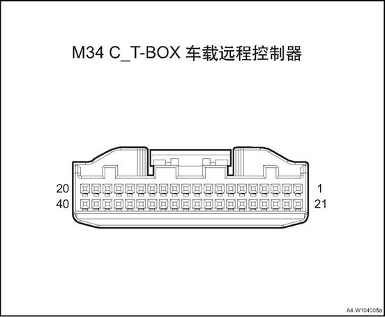
|
Connector No. |
Connector pin |
Wire Color |
Wire Diameter |
Pin Definition |
|
M34 |
1 |
L/R |
0.5 |
B+ Power |
|
M34 |
2 |
P |
0.5 |
PCAN_H |
|
M34 |
3 |
Y |
0.5 |
BCAN_L |
|
M34 |
11 |
Y/R |
0.5 |
SOS button GND |
|
M34 |
12 |
B/Bl |
0.5 |
Audio output + |
|
M34 |
13 |
Gr |
0.5 |
AUX+ |
|
M34 |
14 |
B |
0.5 |
GND 2 |
|
M34 |
15 |
Br/O |
0.35 |
Microphone input |
|
M34 |
18 |
B |
0.5 |
GND 1 |
|
M34 |
20 |
Br |
0.5 |
ACC power supply |
|
M34 |
21 |
B |
0.5 |
GND |
|
M34 |
22 |
V |
0.5 |
PCAN_L |
|
M34 |
23 |
O |
0.5 |
BCAN_H |
|
M34 |
30 |
G/O |
0.5 |
SOS LED output |
|
M34 |
31 |
P |
0.5 |
SOS button input |
|
M34 |
32 |
Bl |
0.5 |
Audio output - |
|
M34 |
33 |
R/O |
0.5 |
AUX GND |
|
M34 |
34 |
Br |
0.5 |
Shielding wire |
|
M34 |
35 |
Gr/R |
0.35 |
Microphone input GND |
|
M34 |
39 |
B |
0.5 |
GND 3 |
![]()
|
Connector No. |
Connector pin |
Wire Color |
Wire Diameter |
Pin Definition |
|
F22 |
1 |
R |
0.5 |
ACC power supply |
|
F22 |
2 |
O/G |
0.5 |
LIN signal |
|
F22 |
5 |
B |
0.5 |
GND |
|
F22 |
6 |
B/W |
0.5 |
B+ Power |
Ⅲ Children Left in Car Safety System
1. Children left in car warning: after the vehicle is powered off and the door and window are closed, the child left in car safety system will enter into the working state. When there are signs of children's activities in the car, the system will recognize the children's activities in the car and transmit the information to the body control module. The body control module controls the left and right steering lights and horns to give sound and light alarm, and at the same time, it can also send the information to the Internet of vehicles platform via the T-Box, which uploads the alarm information to the 400 platform. The platform calls the owner urgently to inform the owner that there are children left in the car.
2. Illegal intrusion alert: after the vehicle is powered off and the door and window are closed, the child left in car safety system will enter into the working state. When violent movement is detected in the car within a certain period of time and there are objects moving in the car, the child left in car system judges that the vehicle has been illegally and violently invaded. The system transmits the information to the body control module, which controls the left and right steering lights and horn for sound and light alarm. At the same time, it is uploaded to the Internet of vehicles platform through T-box, and the Internet of vehicles platform will report to the 400 platform. The platform calls the owner urgently to inform the owner that the vehicle has illegal invasion.
|
System |
Parameter |
Requirements |
|
Children Left in Car Safety System |
Working voltage |
DC9V-16V |
|
Rated voltage |
DC9V-16V |
|
|
Static operating current |
<0.2mA |
|
|
Sensor working frequency |
40KHz±1KHz |
Ⅳ Vehicle Remote Controller Assembly
1. Open the engine cover
2. Disconnect the battery negative cable.
3. Dismantle the glove box assembly refer to glove box assembly
4. Disassemble vehicle remote controller assembly (4G)
![]() 1) Disconnect the wire harness
connector of the vehicle remote controller.
1) Disconnect the wire harness
connector of the vehicle remote controller.
2) Remove the 2 nuts that secure the car remote control assembly.
3) Remove the vehicle remote controller assembly.
Install the car remote controller assembly
![]() 1) Put the remote controller
assembly at the installation position
1) Put the remote controller
assembly at the installation position
2) Remove the 2 nuts that secure the car remote control assembly.
Tightening torque 8 ~ 10N · m
3) Connect the wire harness connector of the vehicle remote controller.
2. Install glove box assembly
3. Connect the battery negative cable.
4. Close the engine compartment cover.
△Attention: after the replacement, the T-BOX replacement process needs to be completed in the after-sales system.
1. Open the engine cover
2. Disconnect the battery negative cable.
3. Dismantle the left front extension panel, refer to the “left front extension panel assembly”.
4. Dismantle the right front extension panel, refer to the “right front extension panel assembly”.
Remove sub-dash panel cover assembly See sub-dash panel cover assembly
6. Remove standby antenna, refer to the “standby antenna”.
Remove sub-dash upper trim assembly See side dash upper trim assembly
8. Dismantle the front storage box, refer to “front storage box assembly”.
9. Dismantle the sub instrument panel house refer to sub instrument panel
10. Remove the steering wheel assembly, refer to the “Steering Wheel Assembly".
11. Disassemble the clock spring.Refer to “Clock Spring”.
12. Dismantle the combination switch assembly, refer to “combination switch assembly”
13. Remove the instrument cluster cover assembly, refer to the “instrument cluster cover assembly”.
14. Disassemble the steering column housing lower shell, refer to “steering column lower shell”.
15. Disassemble the instrument cluster assembly, refer to the “instrument cluster assembly”.
16. Dismantle the dashboard left end cover assembly, refer to the “dashboard left end cover assembly”.
17. Dismantle the dashboard right end cover assembly, refer to the “dashboard right end cover assembly”.
18. Dismantle the fuse box cover, refer to the “fuse box cover”.
19. Remove the driver lower guard assembly, refer to “driver lower guard assembly”.
20. Remove dashboard left vent, refer to the “dashboard left vent”.
21. Remove the central left trim panel assembly. Refer to the “central left trim panel assembly”.
22. Dismantle the glove box assembly refer to glove box assembly
23. Remove the co-pilot side trim panel, refer to “co-pilot side trim panel”.
24. Remove dashboard right vent, refer to the “dashboard right vent”.
25. Dismantle the right and the left A pillar upper panel assembly, refer to the “A pillar upper panel assembly”.
26. Remove the right and the left A pillar lower panel assembly , refer to the “A pillar lower panel assembly”.
27. Dismantle the front display screen, refer the the “front display screen”.
28. Dismantle the front display screen host, refer to the “front display screen host”.
29. Dismantle the 12V on-board power, refer to the “12V on-board power”
30. Dismantle the multimedia interface assembly, refer to the “multimedia interface assembly”.
31. Dismantle the dashboard body assembly, refer to the “dashboard body assembly”
32. Remove the antenna assembly.
![]() 1) Disconnect the wire harness
connector between the vehicle remote controller and the antenna assembly.
1) Disconnect the wire harness
connector between the vehicle remote controller and the antenna assembly.
![]() 2) Remove 2 fixing bolts of the
antenna assembly.
2) Remove 2 fixing bolts of the
antenna assembly.
3) Take off the antenna assembly.
1. Install the antenna assembly.
![]() 1) Put the antenna at installation
position.
1) Put the antenna at installation
position.
2) Install and tighten the 2 fixing bolts of the antenna assembly.
Tightening torque 8 ~ 10N · m
![]() 3) Connect the wire harness
connector between the vehicle remote controller and the antenna assembly.
3) Connect the wire harness
connector between the vehicle remote controller and the antenna assembly.
2. Install the dashboard body assembly.
3. Install the multimedia interface assembly
4. Install the 12V on-board power.
5. Install front screen display body
6. Install the front display screen
7. Install the right and the left A column lower panel assembly
8. Install the right and the left A column upper panel assembly
9. Install the dashboard right vent.
10. Install the co-pilot side trim panel
11. Install the glove box assembly
12. Assemble the central left trim panel assembly
13. Install the dashboard left vent.
14. Install the driver lower guard assembly.
15. Install fuse box cover
16. Install the dashboard right end cover assembly
17. Install the dashboard left end cover assembly
18. Install the instrument cluster assembly.
19. Install the steering column housing lower upper shell
20. Install the instrument cluster cover assembly
21. Install the combination switch assembly
22. Assemble the clock spring
23. Install steering wheel assembly
24. Assemble the sub-dashboard body assembly.
25. Install the front storage box assembly
26) Install the sub-dash panel upper trim assembly
27. Install standby antenna
28. Install rear cover of sub-dash panel.
29. Install the right front extension panel assembly
30. Install the left front extension panel assembly
31). Connect the battery negative cable.
32. Close the engine compartment cover
Usually,the SRS system refers to the whole airbag system,on the cover or other place with airbags,there is SRS mark on it;
1.Driver Airbag - DAB:It will protect the driver’s torso when severe collision happens,and reduce the forward movement in a certain degree . Generally installed in the steering wheel inside, DAB decorative cover is the horn above the steering wheel cover;
2. Passenger Airbag (PAB): Passenger Airbag (PAB): In the event of a serious frontal collision, the passenger directly on the passenger's upper torso, to a certain extent, to prevent the passenger copilot forward movement. It is usually installed inside the instrument panel on the passenger side,can be divided into visible and non-visual
3.Side airbag(SAB) :it provides protection for front passengers and driver The protecting parts is the chest of front person and the hip when side collision happens
Curtain side airbag-CAB: provides additional protection primarily for side passengers. When a serious side collision occurs, it effectively separates the head of the human body from the side trim and window glass of the car, preventing violent collision.
△Attention, please fasten your safety belt as required while driving. Using the airbag only, the protecting effect may be not obvious, if it doesn’t work with the safety belt,it will cause more damage to passengers The airbag is an auxiliary device,it can not replace the safety belt
Components Arrangement
![]()
1. Co-pilot's airbag
2. Right curtain airbag
3. Right side airbag
4. Driver's airbag
5. Airbag controller
6. Left curtain airbag
7. Left side airbag
![]()
Whether the front or side impact, as long as the impact is sufficient, the corresponding airbag will be deployed.
When the collision happens,the collision between vehicle and barrier is called the 1st impact,it reduces speed rapidly;The collision between passengers and vehicle interior structure is called the 2nd impact. Insert an airbag full with air between the passengers and vehicle interior structure rapidly before the 2nd collision happens. Through the air permeability of the air bag itself and the exhaust throttling effect of the vent hole, the kinetic energy of the passengers is absorbed, so that the violent collision can be slowed down and isolated from the internal structural parts, so as to achieve the purpose of protecting the passengers.
The airbag /seat and safety belt are called the vehicle restraint system
|
Pre-tension Explode Safety belt pre-tension load limit Restrain Restrain Airbag Driver/ passenger Airbag
control module Collision Signal SRS system |
Diagnosis of airbag system
After the ignition switch turned to ON position,the indicator on the instrument will extinguish after flickering for a few seconds,it means the system is in normal working condition. If the ignition switch turned to ON position,the indicator doesn’t light or always light,it means the system has problems To ensure the failure reasons,special diagnostics tool is needed to diagnosis
1)Read the DTC by special diagnostics tool
2)Repair according to the DTC mention
3)Clear the DTC by special diagnostics tool Clear the DTC by special diagnostics tool after the troubles been solved
△Attention: Do not use any electrical test devices to test any circuit of SRS system unless these tests are described in the service manual. Do not try to repair/connect/or change the SRS harness,if the wire harness is broken,replace a new one The grounding should be clean
Airbag system maintenance
If the airbag doesn’t explode when the vehicle crash in low speed/side collision/rolls over/rear-end collision,check the following items
Check whether there is any dent/fracture/deformation on the ACU housing or bracket
Check whether the connector is damaged or the terminal has deformation
Check whether the fixing bolts and grounding wire is good
2.The inspection of the airbag system
1)Airbag module
(1) Check pad cover for dents, cracks or deformation.
(2) Check whether the connector is damaged or the terminal has deformation or the wire is stuck
(3) Check whether there is any dent/fracture/deformation on the gas generation housing
(4) Install the air bag components to the steering wheel,check the matching conditions with steering wheel
2)Warning/Caution Label
(1) On steering wheel skeleton.
(2) On driver side airbag module.
(3) On the passenger airbag module.
(4) On the Airbag controller unit(ACU)
(5) Check the instructions on the label when servicing the SRS. Replace signs if they are soiled or damaged. 3)Airbag controller unit(ACU)
△ Warning When the ACU has faults, it must be replaced, do not try repairing.
■The configuration number should be rewritten after airbag replacement
Vehicle configuration number
|
No. |
Power train assembly and drive type |
Configuration |
Structure Number |
Air bag controller variable code |
|
1 |
1.6DVVT+6MT (National-V) / |
Comfort version |
U340A |
03 00 00 00 00 00 00 04 |
|
2 |
Luxury version |
U340B |
C3 00 00 00 00 00 00 04 |
|
|
3 |
1.6DVVT+CVT (National-V) / |
Comfort version |
U341A |
03 00 00 00 00 00 00 04 |
|
4 |
Luxury version |
U341B |
C3 00 00 00 00 00 00 04 |
|
|
5 |
1.5T+6MT (National-V) |
Comfort version |
U3440 |
03 00 00 00 00 00 00 04 |
|
6 |
Luxury version |
U3441 |
C3 00 00 00 00 00 00 04 |
|
|
7 |
Flagship version |
U3442 |
C3 3D 05 18 00 72 00 04 |
|
|
8 |
1.5T+CVT (National-V) |
Comfort version |
U3450 |
03 00 00 00 00 00 00 04 |
|
9 |
Luxury version |
U3456 |
C3 00 00 00 00 00 00 04 |
|
|
10 |
Flagship version |
U3457 |
C3 3D 05 18 00 72 00 04 |
|
|
11 |
1.5T+6MT (National-VI b) |
Comfort version |
U3460 |
03 00 00 00 00 00 00 04 |
|
12 |
Luxury version |
U3461 |
C3 00 00 00 00 00 00 04 |
|
|
13 |
1.5T+CVT (National-VI b) |
Comfort version |
U3470 |
03 00 00 00 00 00 00 04 |
|
14 |
Luxury version |
U3471 |
C3 00 00 00 00 00 00 04 |
|
|
15 |
Flagship version |
U3472 |
C3 3D 05 18 00 72 00 04 |
|
|
16 |
1.2TGDI+6MT (National-VI b) . |
Comfort version |
U342A |
03 00 00 00 00 00 00 04 |
|
17 |
Luxury version |
U342B |
C3 00 00 00 00 00 00 04 |
|
|
18 |
1.2TGDI+6DCT (National-VI b) |
Comfort version |
U343A |
03 00 00 00 00 00 00 04 |
|
19 |
Luxury version |
U343B |
C3 00 00 00 00 00 00 04 |
|
|
20 |
Flagship version |
U343C |
C3 3D 05 18 00 72 00 04 |
3.Disposal method of airbag system component: Before abandoning the airbag or the car equipped with airbag, the airbag shall be detonated.It is forbidden for individuals to detonate airbags without permission.
Please leave it to a professional person to detonate.
|
No. |
Item |
torque(N·m) |
|
1 |
Airbag control module fixing bolt |
8~10 |
|
2 |
Left side airbag |
4~6 |
|
3 |
Copilot airbag fixing bolt |
7~9 |
Airbag connector 1 pin diagram
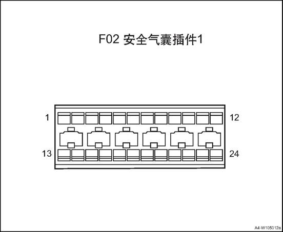
|
Connector No. |
Connector pin |
Wire Color |
Wire Diameter |
Pin Definition |
|
F02 |
1 |
R/O |
0.5 |
power |
|
F02 |
3 |
R/B |
0.5 |
Co-pilot safety belt buckle switch |
|
F02 |
4 |
R/B |
0.5 |
Second row left safety belt buckle switch |
|
F02 |
5 |
Br |
0.5 |
Passenger rear safety belt buckle switch |
|
F02 |
6 |
B |
0.5 |
Analog GND |
|
F02 |
7 |
Bl/R |
0.5 |
Left front collision sensor - |
|
F02 |
8 |
Y/B |
0.5 |
Left front collision sensor + |
|
F02 |
9 |
Y/W |
0.5 |
Right front collision sensor + |
|
F02 |
10 |
P |
0.5 |
Right front collision sensor - |
|
F02 |
11 |
V |
0.5 |
CAN low |
|
F02 |
12 |
P |
0.5 |
CAN_H |
|
F02 |
13 |
W/O |
0.5 |
Driver safety belt buckle switch |
|
F02 |
14 |
G/R |
0.5 |
Passenger rear middle safety belt buckle switch |
|
F02 |
15 |
B |
0.5 |
Digital GND |
|
F02 |
17 |
Y/Bl |
0.5 |
Copilot safety belt pretensioner - |
|
F02 |
18 |
Bl/O |
0.5 |
Copilot safety belt pretensioner + |
|
F02 |
19 |
W/Y |
0.5 |
Driver seat belt pretensioner + |
|
F02 |
20 |
G/W |
0.5 |
Driver seat belt pretensioner - |
|
F02 |
21 |
Bl/B |
0.5 |
Copilot airbag - |
|
F02 |
22 |
P/B |
0.5 |
Copilot airbag + |
|
F02 |
23 |
G |
0.5 |
Driver airbag + |
|
F02 |
24 |
G/R |
0.5 |
Driver airbag - |
![]()
Airbag module B (top line) pin diagram
![]()
|
Connector No. |
Connector pin |
Wire Color |
Wire Diameter |
Pin Definition |
|
F06 |
5 |
G/R |
0.5 |
Right rear safety belt pretensioner - |
|
F06 |
6 |
G/Y |
0.5 |
Right rear safety belt pretensioner + |
|
F06 |
7 |
Y/W |
0.5 |
Left rear safety belt pretensioner + |
|
F06 |
8 |
Y/B |
0.5 |
Left rear seat belt pretensioner - |
|
F06 |
9 |
P |
0.5 |
Co-pilot side collision sensor + |
|
F06 |
10 |
P/B |
0.5 |
Co-pilot side collision sensor - |
|
F06 |
11 |
Bl/B |
0.5 |
Driver side collision sensor - |
|
F06 |
12 |
Bl |
0.5 |
Driver side collision sensor + |
|
F06 |
17 |
Br/B |
0.5 |
Right side airbag - |
|
F06 |
18 |
Br |
0.5 |
Right side airbag + |
|
F06 |
19 |
Gr |
0.5 |
Left side airbag + |
|
F06 |
20 |
Gr/B |
0.5 |
Right side airbag - |
![]()
|
F06 |
21 |
B/Bl |
0.5 |
Right curtain airbag - |
|
F06 |
22 |
Bl/O |
0.5 |
Right curtain airbag + |
|
F06 |
23 |
Y |
0.5 |
Left curtain airbag + |
|
F06 |
24 |
Y/B |
0.5 |
Left curtain airbag - |
Airbag Module (middle line) pin diagram
![]()
|
Connector No. |
Connector pin |
Wire Color |
Wire Diameter |
Pin Definition |
|
F52 |
1 |
R/O |
0.5 |
power |
|
F52 |
6 |
B |
0.5 |
Analog GND |
|
F52 |
7 |
Bl/R |
0.5 |
Left front collision sensor - |
|
F52 |
8 |
Y/B |
0.5 |
Left front collision sensor + |
|
F52 |
9 |
Y/W |
0.5 |
Right front collision sensor + |
|
F52 |
10 |
P |
0.5 |
Right front collision sensor - |
|
F52 |
11 |
V |
0.5 |
CAN low |
|
F52 |
12 |
P |
0.5 |
CAN_H |
|
F52 |
13 |
W/O |
0.5 |
Driver safety belt buckle switch |
|
F52 |
15 |
B |
0.5 |
Digital GND |
|
F52 |
21 |
Bl/B |
0.5 |
Copilot airbag - |
|
F52 |
22 |
P/B |
0.5 |
Copilot airbag + |
|
F52 |
23 |
G |
0.5 |
Driver airbag + |
|
F52 |
24 |
G |
0.5 |
Driver airbag - |
Ⅲ Airbag Controller Unit (ACU)
1. Open the engine cover
2. Close the ignition switch,disconnect the negative port of the battery,wait at least 3mins until the capacitance inside the ACU is discharged totally.
3. Dismantle the sub instrument panel house refer to sub instrument panel
4. Remove the airbag controller.
![]() 1) Disconnect airbag controller
harness connector 1.
1) Disconnect airbag controller
harness connector 1.
2) Remove the 3 fixing bolts of the airbag controller .
3) Remove the airbag controller.
△ Attention: Do not drop or crash the ACU.
1. Install the airbag controller
1) Put the airbag controller at installation position.
![]() 2) Mount and tighten the 3 fixing
bolts of the airbag controller .
2) Mount and tighten the 3 fixing
bolts of the airbag controller .
△Attention: The arrow on the airbag controller is aligned with the vehicle's driving direction. Tighten torque 8~10N·m
3) Connect airbag controller harness connector 1.
Install sub-dashboard body assembly
3. Connect the battery negative cable.
4. Close the engine compartment cover.
△Attention: After the ACU is replaced, the configuration number shall be rewritten. See the overview for the specific model configuration number.
1. Open the engine cover
2. Disconnect the battery negative cable.
△Warning: It takes At least 3 minutes until the discharge of energy storage capacitor in ACU is completed.
![]() 3. Remove the driver airbag.
3. Remove the driver airbag.
1) Using a cross screwdriver to push the spring 1 from the back of the
steering wheel.
2) Using a cross screwdriver to push the spring 2 from the back of the
3) steering wheel.
4) Using a cross screwdriver to push the spring 3 from the back of the
5) steering wheel.
![]() 4) Disconnect the driver airbag
harness connector.
4) Disconnect the driver airbag
harness connector.
5) Remove the driver airbag.
△Attention
■When demounting the driver air bag assembly and install new airbag assembly, place the liner frontage upward.
■Do not measure the resistance of the airbag It may cause the airbag
explode by accident
■Keep the driver airbag in place where the temperature lower than 80 ℃ and away from noise and electricity
■During the welding work,disconnect the negative port of the battery and connector
■When deserting a vehicle or airbag,use special tools to explode the airbag
Install the driver's airbag
1) Put the airbag controller at installation position.
![]() 2) Connect the driver airbag
harness connector.
2) Connect the driver airbag
harness connector.
![]() 3) Install the driver's airbag into
the steering wheel and ensure that the three jaws snap into place.
3) Install the driver's airbag into
the steering wheel and ensure that the three jaws snap into place.
2). Connect the battery negative cable.
3. Close the engine compartment cover
△Attention: After the airbag is replaced, the configuration number shall be rewritten. See the overview for the specific model configuration number.
1. Open the engine cover
2. Disconnect the battery negative cable.
△Warning: It takes At least 3 minutes until the discharge of energy storage capacitor in ACU is completed.
3. Remove the dashboard body assembly, refer to the dashboard body assembly
4. Disassemble the co-pilot airbag
![]() 1) Remove the 2 fixing screws of
the co-pilot airbag.
1) Remove the 2 fixing screws of
the co-pilot airbag.
2) Remove the co-pilot airbag
△Attention: Do not place or post anything on the airbag surface.
1. Install the co-pilot airbag.
1) Put the airbag at installation position.
![]() 2) Mount and tighten the 2 fixing
screws of the co-pilot airbag.
2) Mount and tighten the 2 fixing
screws of the co-pilot airbag.
Tightening torque 7 ~ 9N·m
2. Install the dashboard body assembly.
3. Connect the battery negative cable.
4. Close the engine compartment cover.
△Attention: After the airbag is replaced, the configuration number shall be rewritten. See the overview for the specific model configuration number.
△Attention: left and right airbag assembly and disassembly methods are similar
△Attention: Side airbags are mounted on the driver's seat and passenger's seat backrest respectively. Side airbags are installed inside the backrest when the seat assembly is assembled, and disassembly of the side airbags can damage the seat. Therefore, it is not allowed to install and remove side airbags by unskilled service personnel. When maintenance is required, replace the seat assembly with side airbags.
1. Open the engine cover
2. Disconnect the battery negative cable.
△Warning: It takes At least 3 minutes until the discharge of energy storage capacitor in ACU is completed.
3. Dismantle the left side airbag
![]() 1) Remove the seat outer coating.
1) Remove the seat outer coating.
△Attention: Do not squeeze or seat on the seat backrest while maintaining seats with side airbags.
![]() 2) Disconnect airbag controller
harness connector 1.
2) Disconnect airbag controller
harness connector 1.
3) Remove the 2 fixing bolts of the airbag controller .
4) Remove the left side airbag
1. Install the left side airbag
1) Put the airbag at installation position.
![]() 2) Mount and tighten the 2 fixing
bolts of the airbag controller .
2) Mount and tighten the 2 fixing
bolts of the airbag controller .
Tightening torque 4~6N·m
3) Connect airbag controller harness connector 1.
![]() 4) Install the seat outer coating.
4) Install the seat outer coating.
2). Connect the battery negative cable.
3. Close the engine compartment cover
△Attention: left and right airbag assembly and disassembly methods are similar
1. Open the engine cover
2. Disconnect the battery negative cable.
△Attention: After the airbag is replaced, the configuration number shall be rewritten. See the overview for the specific model configuration number.
3. Dismantle the right and the left A pillar upper panel assembly, refer to the “A pillar upper panel assembly”.
4. Dismantle the left and the right front doorsill guard plate assemblies, refer to the ”front doorsill guard plate assembly”.
5. Dismantle the left and the right rear doorsill guard plate assemblies, refer to the ”rear doorsill guard plate assembly”.
6. Remove B pillar lower guard assemblies. See B pillar lower guard assembly
7. Remove B pillar upper guard assembly. See B pillar upper guard assembly
8. Remove the rear seat assembly. See the rear seat assembly
9. Remove the C pillar lower guard plates and luggage compartment guard plate. Refer to the “C pillar lower guard plate” and the “luggage compartment guard plate”.
10. Remove C pillar upper guard assemblies. See C pillar upper guard assembly
11. Dismantle the sun visor assembly(left/right) . refer to the “sun visor assembly”.
12. Dismantle the front roof lamp refer to the front roof lamp
13. Remove left and right wall lamp assemblies, refer to the “left wall lamp assembly”
14. Remove the right and the left roof handles. See “side roof handle”.
15. Dismantle the roof assembly refer to the roof assembly
16. Remove the left curtain airbag.
![]() 1) Disconnect left curtain airbag
controller harness connector 1.
1) Disconnect left curtain airbag
controller harness connector 1.
![]() 2) Remove the 7 fixing bolts of
left curtain airbag.
2) Remove the 7 fixing bolts of
left curtain airbag.
3) Remove the left curtain airbag and place it properly.
1. Install the left curtain airbag
![]() 1) Put the airbag at installation
position.
1) Put the airbag at installation
position.
2) Mount and tighten the 7 fixing bolts of the left curtain airbag.
Tightening torque 7 ~ 9N·m
![]() 3) Connect left curtain airbag
controller harness connector 1.
3) Connect left curtain airbag
controller harness connector 1.
2. Install the roof assembly
3. Install the left and the right side roof handles.
4. Install left and right side wall lamp assemblies
5. Install the front roof lamp assembly
6. Install the sun visor assembly
7. Install the right and the left C pillar upper guard assemblies.
8. Install the right and the left C pillar lower guard assemblies.
9. Install the rear row seat assembly
10. Install the right and the left B pillar upper guard assemblies.
11. Install the right and the left B pillar lower guard assemblies.
12. Install left rear doorsill guard plate assembly.
13. Install the front doorsill guard plate assembly.
14. Install the right and the left A column upper panel assembly
15). Connect the battery negative cable.
16. Close the engine compartment cover
Advanced Driver Assistance System
Advanced driving assistance system (ADAS) uses various sensors installed in the car to sense the surrounding environment, collect data, identify, detect and track static and dynamic objects at any time in the process of vehicle driving. Combined with the navigation map data, ADAS carries out system calculation and analysis, so as to let the driver detect in advance the possible danger, effectively increase the comfort and safety of car driving.
360 panoramic system around the car to set up to cover all the surrounding area around the vehicle wide-angle 4 wide-angle camera on the same time collected multi-channel video image processing into a vehicle around the 360-degree top view of the body, and finally displayed on the MP5 screen, Let the driver clearly check whether there are obstacles around the vehicle and understand the relative position and distance of obstacles to help drivers parked vehicles easily.
![]()
1. Front anti-collision radar sensor
2. Panoramic parking front camera
3. Front anti-collision radar sensor
4. Panoramic parking left camera
5. Panoramic parking right camera
6. Rear anti-collision radar sensor
7 Rear anti-collision radar sensor
8. Rear anti-collision radar sensor
9. Rear anti-collision radar sensor
10. Panoramic parking rear camera
|
No. |
Fault symptoms |
Fault analysis |
Solutions |
Remark |
|
1 |
Reversing the system does not work |
Reversing switch not connected |
Replace the reversing switch |
Refer to system failure |
|
Poor connection to the main power |
Check harness for connection |
|||
|
The connector is not connected properly |
Reconnect all connectors correctly |
|||
|
2 |
Sensor fault |
The socket is not positioned correctly, so the sensor does not work |
Reconnect all sensor sockets correctly |
Refer to sensor failure. |
|
3 |
Buzzer alarm, but no obstacles behind the car |
Test the body or ground |
According to the instructions correctly installed, if necessary, guide the inspection of professional technicians |
|
|
Sensor installed incorrectly or off |
||||
|
Sensor damaged |
Sensor damage please promptly replaced |
|||
|
Sensor cable is damaged |
Check harness for damage |
|||
|
4 |
Not correctly display the distance of obstacles |
Battery voltage is abnormal |
Check the battery voltage is normal |
|
|
Socket location is incorrect |
Turn off the system and reconnect all outlets correctly |
|||
|
The sensor harness is disturbed |
Check if the sensor cable touches the exhaust pipe or silencer |
|||
|
5 |
Boot no beep, the other work is normal and no warnings when working |
Instrument failure (buzzer integrated in the meter) |
Check the instrument cable and socket, and reconnect the meter correctly |
|
|
Replace the instrument cluster |
|
Steps |
Inspection content |
Solution |
Decision specification |
Next step |
|||||||
|
Yes |
No |
||||||||||
|
1 |
Confirm the fault phenomenon |
Turn the ignition switch ON and put the transmission in reverse gear. |
Can you hear buzzer alarm? |
Handle intermittent problems and go to the next step |
Turn to step 3 |
||||||
|
2 |
Check for intermittent failure |
Check and handle the reversing light switch harness connector looseness fault. Check and handle the combination harness connector failure. |
|
|
|
||||||
|
3 |
Check the reversing lamp insurance |
Remove the backup lamp fuse, check whether it is blown? |
Check if the fuse is blown |
Replace fuse |
Next step |
||||||
|
4 |
Check reversing radar control module power |
Use a multimeter to measure the voltage between the corresponding terminals of the reversing radar control module harness connector and the ground. |
Voltage Standard: 11 ~ 14 V. Voltage is within standard? |
Next step |
Repair or replace the wiring harness |
||||||
|
5 |
Check reversing radar control module |
Use a multimeter to measure the revering radar. |
Standard resistance value: <1Ω |
Next step |
Repair or replace the wiring harness |
|
||||||
|
Reversing radar control module wire harness connection |
|
|||||||||||
|
Check the ground connecting wiring |
Check whether the resistance between radar corresponding pin and ground meets the requirement |
. |
|
|||||||||
|
6 |
Check the line between the reversing radar control module and the reversing lamp fuses |
Select R gear Measure the resistance Measure the resistance between the corresponding terminals of the reverse radar control module harness connector and the corresponding terminals of the reverse lamp fuse harness connector. . |
Standard resistance: less than 1Ω. Whether the resistance meets the standard? |
Next step |
Repair or replace the wiring harness |
|
||||||
|
7 |
Replace the reversing radar control module Whether the fault is cleared? |
Replace a new reversing radar control module Control module / Turn the key switch ON and put the vehicle in reverse gear. |
Whether the buzzer beeps? Cue tone? |
Fault removed |
|
|
||||||
|
Steps |
Inspection content |
Solution |
Decision specification |
Next step |
|
|
Yes |
No |
||||
|
1 |
Confirm the fault phenomenon |
Turn the ignition switch at ON, select R gear, and place appropriate obstacles in the proper distance from the rear of the vehicle. |
Is it possible to hear parking alert sounds? |
Handle intermittent problems and go to the next step |
Turn to step 3 |
|
2 |
Check for intermittent failure |
Check and handle the reversing radar sensor harness connector looseness fault. |
|
|
|
|
3 |
Check the wiring between the reversing radar sensor and the reversing radar control module |
Measure the resistance between the corresponding terminal of the reversing radar sensor harness connector and the corresponding terminal of the reversing radar control module. |
Standard resistance: less than 1Ω. Whether the resistance meets the standard? |
Next step |
Repair or replace the wiring harness |
|
4 |
Check reversing radar sensor ground wiring |
Measure the resistance between the appropriate terminal of the reversing radar sensor harness connector and the ground. |
Standard resistance: less than 1Ω. Whether the resistance meets the standard? |
Next step |
Repair or replace the wiring harness |
|
5 |
Replacing the reversing radar sensor, fault removed? |
Replace a new reversing radar sensor, set the ignition switch at ON, shift the transmission into reverse gear, and enter the reversing state. |
Can detect obstacles? |
Fault removed |
|
|
No. |
Item |
torque(N·m) |
|
1 |
Panoramic parking controller |
9~11 |
|
2 |
Anti-collision radar controller |
4~6 |
High definition 360° panoramic parking controller

|
Connector No. |
Connector pin |
Wire Color |
Wire Diameter |
Pin Definition |
|
F45 |
3 |
O |
0.5 |
CAN_H input |
|
F45 |
5 |
Gr |
0.5 |
ACC_ON signal input |
|
F45 |
6 |
R |
0.5 |
Battery power input |
|
F45 |
9 |
Y |
0.5 |
CAN_L input |
|
F45 |
12 |
B |
0.5 |
Controller power negative input |
Reversing radar module pin diagram

|
Connector No. |
Connector pin |
Wire Color |
Wire Diameter |
Pin Definition |
|
F48 |
10 |
O |
0.5 |
CAN_H |
|
F48 |
13 |
B |
0.5 |
Analog GND |
|
F48 |
14 |
B/R |
0.35 |
Sensor GND |
|
F48 |
20 |
Br/B |
0.35 |
High voltage input |
|
F48 |
21 |
Br |
0.35 |
Low voltage drive |
|
F48 |
23 |
G/B |
0.35 |
Sensor power supply |
|
F48 |
24 |
R/O |
0.5 |
IGN signal |
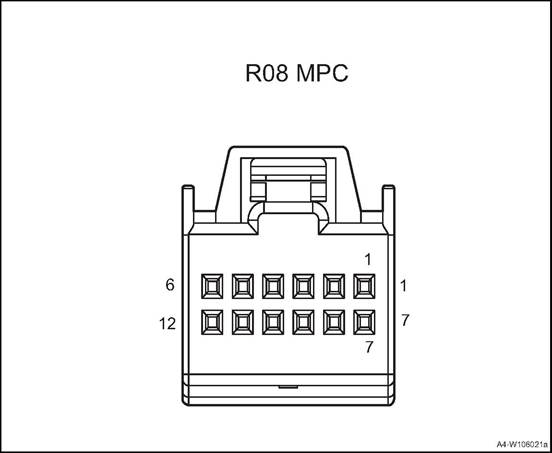
|
Connector No. |
Connector pin |
Wire Color |
Wire Diameter |
Pin Definition |
|
R08 |
1 |
G |
0.5 |
Private CAN_L |
|
R08 |
2 |
V |
0.5 |
Public CAN low |
|
R08 |
5 |
B |
0.5 |
GND |
|
R08 |
6 |
R |
0.5 |
IG1 signal |
|
R08 |
7 |
Br |
0.5 |
Private CAN_H |
|
R08 |
8 |
P |
0.5 |
Public CAN_H |
1. Open the engine cover
2. Disconnect the battery negative cable.
3. Remove front bumper body assembly. See front bumper assembly
4. Remove the rear bumper assembly. Refer to the rear bumper assembly
5. Dismantle the front anti-collision radar sensor
1) Disconnect the front radar sensor harness connector.
2) Pry up the buckles, and take out the reversing radar sensor.
△Attention: there are two front anti-collision radar sensors, the dismantling methods are similar.
![]()
![]() 6. Dismantle rear anti-collision
radar sensor
6. Dismantle rear anti-collision
radar sensor
1) Disconnect the rear radar sensor harness connector.
2) Pry up the buckles, and take out the reversing radar sensor.
![]() 1. Install rear anti-collision
radar sensor
1. Install rear anti-collision
radar sensor
1) Install the reversing radar sensor to the rear bumper.
2) Connect the rear radar sensor harness connector.
![]() 2. Install the front anti-collision
radar sensor
2. Install the front anti-collision
radar sensor
1) Install the reversing radar sensor to the front bumper.
2) Connect the front radar sensor harness connector.
3. Install rear bumper assembly
4. Install front bumper assembly
5. Connect the battery negative cable
6. Close engine compartment cover
Ⅳ Reverse Radar Controller Assembly
1. Open the engine cover
2. Disconnect the battery negative cable.
3. Remove the spare tyre cover assembly. See the “spare tyre cover assembly”.
4. Remove the C pillar lower guard plates and luggage compartment guard plate. Refer to the “C pillar lower guard plate” and the “luggage compartment guard plate”.
5. Disassemble the reverse radar controller assembly.
1) Disconnect the reverse radar sensor controller assembly harness connector 1.
2) Disassemble the 2 fixing nuts of the reverse radar controller assembly.
![]() 3) Take out the reverse radar
controller assembly.
3) Take out the reverse radar
controller assembly.
1. Install reversing radar controller assembly
1) Put the reverse radar controller assembly at the installation position
2) Mount and tighten the 2 fixing nuts of the reverse radar controller assembly.
Tightening torque 4~6N·m
3) Connect the reversing radar controller assembly harness connector.
2. Install the right C pillar lower guard plate and luggage compartment guard plate.
![]() 3. Install the spare tyre cover
assembly.
3. Install the spare tyre cover
assembly.
4). Connect the battery negative cable.
5. Close the engine compartment cover
1. Open the engine cover
2. Disconnect the battery negative cable.
3. Dismantle the driver seat, refer to the “front seat”
![]() 4. Dismantle the panoramic parking controller.
4. Dismantle the panoramic parking controller.
1) Remove the maintenance carpet.
1) Disconnect panoramic parking controller harness connector 1.
3) Remove the 3 fixing bolts of the panoramic parking controller.
4) Take out the controller.
1. Install panoramic parking controller.
1) Put the panoramic parking controller at installation position.
![]() 2) Mount and tighten the 3 fixing
bolts of the controller .
2) Mount and tighten the 3 fixing
bolts of the controller .
Tightening torque 9 ~ 11N · m
3) Connect panoramic parking controller harness connector 1.
4) Cover the maintenance carpet.
2. Install the driver seat.
3. Connect the battery negative cable.
4. Close the engine compartment cover.
Ⅵ Panoramic Parking Front Camera
1. Open the engine cover
2. Disconnect the battery negative cable.
3. Remove front bumper body assembly. See front bumper assembly
4. Dismantle the panoramic parking front camera
1) Disconnect panoramic parking front camera harness connector 1.
![]() 2) Remove the 2 screws for
panoramic parking front camera.
2) Remove the 2 screws for
panoramic parking front camera.
3. Take out the panoramic parking front camera
1. Install panoramic parking front camera
1) Put the panoramic parking front camera at installation position.
![]() 2) Fasten the 2 screws for
panoramic parking front camera.
2) Fasten the 2 screws for
panoramic parking front camera.
1) Connect panoramic parking front camera harness connector 1.
2. Install front bumper assembly
3. Connect the battery negative cable.
4. Close the engine compartment cover.
Remove the left and right panoramic parking cameras. Refer to the left and right outer rearview mirror assembly.
1. Open the engine cover
2. Disconnect the battery negative cable.
3. Disassemble tail door trim panel assembly. See the “tail door trim panel assembly”.
4. Remove left and right tail door combination lamp assembly. Refer to the “tail door combination lamp”
5. Dismantle the panoramic parking rear camera
![]() 1) Disconnect panoramic parking
rear camera harness connector 1.
1) Disconnect panoramic parking
rear camera harness connector 1.
2) Remove 2 fixing bolts of tail door trim strip assembly.
3) Remove tail door trim strip assembly.
![]() 4) Remove the 2 screws for
panoramic parking rear camera.
4) Remove the 2 screws for
panoramic parking rear camera.
5) Take down the panoramic parking rear camera
1. Install panoramic parking rear camera
![]() 1) Put the panoramic parking rear
camera at installation position.
1) Put the panoramic parking rear
camera at installation position.
2) Mount and tighten the 2 screws for panoramic parking rear camera.
![]() 3) Put the tail door trim strip
assembly at installation position.
3) Put the tail door trim strip
assembly at installation position.
2) Mount and tighten the 2 fixing bolts of tail door trim strip assembly.
5) Connect panoramic parking rear camera harness connector 1.
2. Install tail door left and right combination lamps
3. Install tail door trim panel assembly
4). Connect the battery negative cable.
5. Close the engine compartment cover
△Attention: left and right left blind spot monitoring radar assembly and disassembly methods are similar
1. Open the engine cover
2. Disconnect the battery negative cable.
3. Remove the rear bumper assembly. Refer to the rear bumper assembly
4. Dismantle the left blind spot monitoring radar.
![]() 1) Disconnect the left blind spot
monitoring radar harness connector 1.
1) Disconnect the left blind spot
monitoring radar harness connector 1.
2) Dismantle the3 fixing screws 2 of left blind spot monitoring radar.
3) Take off the left blind spot monitoring radar.
1. Install the left blind spot monitoring radar.
1) Put the left blind spot monitoring radar at installation position.
2) Mount and tighten the 3 fixing screws 2 of left blind spot monitoring radar.
![]() Tightening torque 6 ~ 9N·m
Tightening torque 6 ~ 9N·m
1) Connect the left blind spot monitoring radar harness connector 1.
2. Install rear bumper assembly
3. Connect the battery negative cable.
4. Close the engine compartment cover.
1. Open the engine cover
2. Disconnect the battery negative cable.
3. Dismantle the Lane Deviation Camera
1) Remove the left side cover.
![]() 1) Disconnect the lane deviation
camera harness connector 1.
1) Disconnect the lane deviation
camera harness connector 1.
3) Remove the lane deviation camera from the slot 2.
1. Install the Lane Deviation Camera
![]() 1) Put the lane deviation camera in
the slot 2.
1) Put the lane deviation camera in
the slot 2.
1) Connect the lane deviation camera harness connector 1.
3) Install the left side cover.
2). Connect the battery negative cable.
3. Close the engine compartment cover
1. Open the engine cover
2. Disconnect the battery negative cable.
3. Remove front bumper body assembly. See front bumper assembly
4. Dismantle the Front millimeter-wave radar
![]() 1) Dismantle the front
millimeter-wave radar cover.
1) Dismantle the front
millimeter-wave radar cover.
![]() 2) Disconnect the front
millimeter-wave radar harness connector.
2) Disconnect the front
millimeter-wave radar harness connector.
3) Take down the front millimeter-wave radar
1. Install the front millimeter-wave radar
![]() 1) Put the front millimeter-wave
radar at installation position.
1) Put the front millimeter-wave
radar at installation position.
2) Connect the front millimeter-wave radar harness connector.
![]() 3) Install the front millimeter-wave radar cover.
3) Install the front millimeter-wave radar cover.
2. Install front bumper assembly
3. Connect the battery negative cable.
4. Close the engine compartment cover.
After-sales calibration is available for vehicle at 4S or service store when replacing camera or incorrect panoramic display exists
|
Calibration tool |
Calibration tool requirements |
|
Portable diagnosis device |
Writing VIN code, assembly date, vehicle configuration information, related calibration, window form and body color |
|
Calibration cloth |
The calibration cloth matched with the ordinate technology algorithm |
|
|
After-sales calibration cloth consists of four pieces, non-reflective materials (such as non-woven or oxford cloth),calibration cloth specific style and size are as follows: Front and rear calibration cloth:
Front
calibration cloth: Rear calibration cloth:
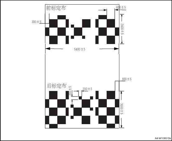
![]()
![]() Left calibration cloth and right calibration cloth:
Left calibration cloth and right calibration cloth:
Work flow of after-sale calibration
1) Choose calibrating place: Flat ground, width around 6 meters, length around 9 meters; (please choose zero-wind or indoor conditions so as to prevent wind’s effects on calibration cloth)
2) Park the vehicle at place’s central location, then place calibrating cloths around the vehicle by following instructions on picture below. Each piece of calibration cloth has corresponding direction mark on it: front-left, front-right, rear-left, rear-right, left-front, left-rear, right-front and right-rear.place according to the direction indication;
3) Connect diagnostic scanner through OBD interface. Ensure vehicle door and trunk lid are closed
4) Activate calibration through diagnostic apparatus, then choose “manual calibration” Please refer to “2. OBD calibration workflow” for the processes of manual calibration
5) Choose corresponding calibrating point. Please refer to “3. Operations of manual calibration” for details
6) Check calibration effect
7) Calibration finished
Center
line of large car body Center
line of conventional vehicle body Front
wheel position Front
wheel position The small
black block is mainly to improve the camera recognition accuracy, and the size
requirement is 20cm × 20cm The
center line of conventional vehicle (less than 4.8 m) - it is the line
identification for the middle position of vehicle body when parking The
center line of large vehicle (4.8 m ~ 5.2 m) - it is used to identify the
middle position of vehicle body when parking. Note: Rear
wheel position Rear
wheel position
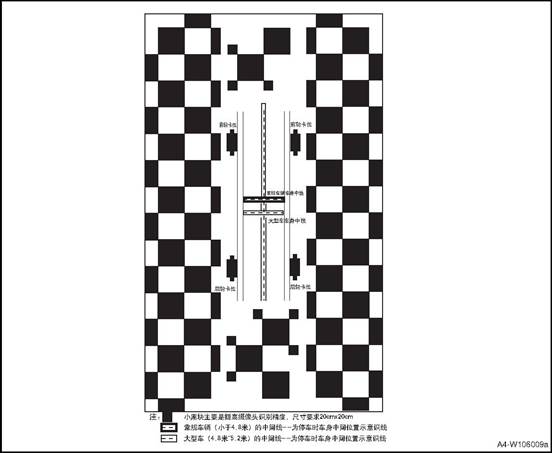
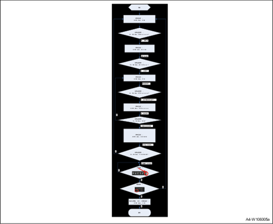
1)Diagnostic session control = extended Diagnostic
session
03 ECU must enter extended mode to perform panoramic calibration
2)Read Data By Identifier = Read Ecu SN.
Read the SN number of ECU and calculate the security key
3)Security access = read seed/send key
Security access authentication uses the service for security authentication and
unlocks the calibration routine service.
4)Routine Control =start avm calibration
Trigger panoramic calibration
With this service, diagnostic apparatus can command ECU to check basic conditions for calibration, and start calibration when all conditions are met (motionless, non-R gear, all doors closed)
5)Select point calibrating selected point
When calibration starts, ECU will keep checking routine results (31 03 02 01). If calibration succeeds, the apparatus will display success, or failed if not.
6)![]() Press exit to save
Press exit to save
When all points have been selected, which means manual calibration has finished, please save data before exit. 1. Press exit first as shown in picture below
![]() 22. Press √ to save
22. Press √ to save
7)Diagnostic session control = Default Diagnostic session
Default reply
when calibration is complete, diagnostic apparatus will command ECU to restore default mode Reset ECU, after sending 11 03 and clicking exit save, the diagnostic instrument will send a reset command to reset ECU.
The command must be sent after clicking exit save
8)TesterPresent = ECU online
To ensure diagnostic apparatus is always online during calibration process, please send 3E service regularly
.
Note: 1) Please press “save and exit” after calibration is finished, or the calibrating data cannot be saved, which will make calibration failed
2) After pressing “save and exit”, please use apparatus to send reset command to ECU.
3) AVM will switch to manual calibration when panoramic system has received the command. User can adjust corresponding selected points through interface on MP5 to complete calibration. Please refer to the processes below for detailed operation of selecting point.
CAN Communication Parameters
The addressing scheme and the CAN identifier assignment can be referred to the project CAN Matrix.
The DLC of the download CAN-message is fixed to 8 bytes。 The DLC of the download CAN-message is fixed to 8 bytes。
The padding bytes are defined as 0x00
1) Ensure all doors and trunk lid are closed, and all rear-view mirrors are unfolded before operation;
![]() 2) Use diagnosis device to switch to manual
calibration and open the page of front-camera calibration. The manual
calibration can be operated on MP5; Front camera calibration and target point
image.
2) Use diagnosis device to switch to manual
calibration and open the page of front-camera calibration. The manual
calibration can be operated on MP5; Front camera calibration and target point
image.
3) The top-view on image’s right side is the area for calibration. The small red box in the big box on right side is the selected point’s area currently. The image’s left side shows the picture captured by camera that is under calibration. Please manually click the front, rear, left and right areas on top-view image for choosing corresponding camera for calibration. (The following guidance for manual calibration is based on front-camera).
![]() 4) On the main view
4) On the main view![]() represents the location of
calibration point,represents the current calibrating point. Click the point to
partially enlarge the picture.
represents the location of
calibration point,represents the current calibrating point. Click the point to
partially enlarge the picture.
5)
Please use ![]() to
adjust the center of blue box. Please make the center
to
adjust the center of blue box. Please make the center ![]() coincide with the opposite corner
of two black squares (target point’s location)
coincide with the opposite corner
of two black squares (target point’s location)
6)
Click![]() to
confirm, and proceed the choosing of next calibrating point (following step (4)
and (5))
to
confirm, and proceed the choosing of next calibrating point (following step (4)
and (5))
7) Calibrating order is fixed and cannot be skipped ( please proceed calibration by following step 1, 2, 3, 4 and 5)
8) When calibration of front camera is finished, please click the left, right and rear area on the top-view to choose corresponding camera, and carry out calibration process.
![]() Left-camera calibration and image
of target point (please follow step (4), (5), (6) and (7))
Left-camera calibration and image
of target point (please follow step (4), (5), (6) and (7))
![]() Right-camera calibration and image
of target point
Right-camera calibration and image
of target point
![]() Rear-camera calibration and image of target point:
Rear-camera calibration and image of target point:
9) When all four cameras have been calibrated,
please check the calibration’s result. If the image is ok, please click![]() and choose “√” to save
and choose “√” to save
10) When all operations are completed, please use a diagnosis device to send reset command. The system will reset and calibration is complete.
.
![]()
XIII MRR Front Millimeter Wave Radar After-sale Calibration Procedure
1 Conditions Need Radar After-sale Calibration
After-sale calibration uses gradienter calibration and driving calibration. First use gradienter to calibrate vertical direction, and then use driving calibration to calibrate horizontal direction, and finally make the deviation between driving axis line and radar axis line be in certain range.
1. It needs to calibrate radar when there are the following conditions:
1) When radar report error and read fault code DTC_MRR_MISALIGNED
2) Replace a new radar assembly, such as replace radar or radar bracket;
3) When vehicle driving axis line is changed, such as a vehicle has done the 4-wheel alignment again;
Radar calibration platform, including a calibrated vehicle, a gradienter and a calibration computer.
1. Measure the inclination of the ground.
2. Park the vehicle in the horizontal area, remove the components around the radar and install the gradienter correctly. Adjust vertical calibration bolts(lower right bolt), make the value in gradienter
close to the ground inclination value, and ensure the error within ± 0.3
3. Carefully remove the gradienter to avoid the influence on the vertical angle during the disassembly process Install other components such as bumpers(with licenses) and check the condition of the vehicle to ensure safe driving on public roads.
4. Start the after-sales calibration service through the diagnostic device. Click "start driving calibration"
5. Drive according to the requirements of driving mode until the calibration progress bar reaches 100%.
△Attention: The calibration progress bar reaches 100% usually takes about 20 minutes.(depending on roads and targets)
6. Adjust the horizontal alignment bolts (upper left bolts) according to the requirements of the calibration results.
7. If the first result is out of tolerance, the driving calibration service shall be performed again after adjusting the calibration bolts to ensure the completion of the calibration.
8. If the calibration fails after more than 45 minutes, please check whether the calibration environment, driving conditions, installation location and so on are correct, whether the driving calibration requirements are followed.
9. Repeat the above steps after confirmation.
1. Environmental conditions for vertical calibration
The vertical calibration of radar is carried out by the gradienter, and the calibration requirements are as follows:
1) The calibration site for parking vehicles shall be horizontal, with an inclination of - 0.3-0.3 ° or measurable.
![]() 2) Ensure that the radar surface is
clean, especially at the three installation positioning points (k points) of
the gradienter.
2) Ensure that the radar surface is
clean, especially at the three installation positioning points (k points) of
the gradienter.
Position precision
2. Environmental conditions for horizontal calibration
The horizontal calibration of radar is carried out by the gradienter, and the calibration requirements are
as follows:
1) The radar surface shall be clean and free of snow, soil and other coverings
2) Avoid calibration in snow and rain.
3) Both sides of the road need static metal targets, such as lamp posts, road signs, etc.,
High-speed or elevated roads with metal railings are recommended.
3. Driving conditions of driving calibration mode
After starting the driving calibration, the vehicle must be driven under certain conditions
so that the progress bar of driving calibration can be gradually increased to 100%. The driving conditions for driving calibration are
as follows:
|
Limit conditions |
Threshold value |
Out of tolerance prompt |
||
|
Min. vehicle speed |
40km/h |
Speed too low |
||
|
Max. vehicle speed |
120km/h |
Speed too high |
||
|
Limit conditions |
Threshold value |
Out of tolerance prompt |
|
||
|
Min. longitudinal acceleration |
-0.5m/s² |
Longitudinal acceleration is too small |
|
||
|
Max. longitudinal acceleration |
1.0m/s² |
Longitudinal acceleration is too large |
|
||
|
Max. lateral acceleration |
2.0m/s² |
Lateral acceleration is too large |
|
||
|
Max. turning curvature |
0.001m/km |
Turning curvature too large |
|
||
|
ABS,ASR,ESP. MSR Activated |
- |
Vehicle dynamic condition interference |
|
||
4. Cause of calibration failure
The calibration of the driving calibration service may fail if:
1) Driving conditions always do not meet the requirements: surrounding reference, road conditions
2) The communication between the diagnostic device and the vehicle is interrupted during calibration.
3)The installation deviation of radar is too large.
5. Calibration Operation
Check the condition of the vehicle to ensure that the vehicle is driven on the test road that meets the requirements, and calibrate the horizontal driving calibration service according to the following process Serial number manual operation data flow (hexadecimal) description:
|
No. |
Manual operation |
Data flow (hexadecimal) |
Instructions |
|
1 |
Click to start SDA |
781 02 10 03 00 00 00 00 00 789 06 50 03 00 32 01 F4 00 |
Enter extension mode |
|
2 |
- |
781 02 27 01 00 00 00 00 00 789 06 67 01 XX XX XX XX00 781 06 27 02 YY YY YY YY00 789 02 67 02 00 00 00 00 00 |
Security access algorithm, refer to the diagnostic specification key-seed algorithm XX: seed YY: key |
|
3 |
- |
781 04 2E 34 24 00 789 03 6E 34 24 |
Turn on the production line mode of ECU and set it to 00 |
|
4 |
- |
781 10 17 2E F1 A8 xx xx xx(20 Bytes) 789 03 6E F1 A8 781 03 22 F1 A8 789 10 17 62 F1 A8 xx xx xx (20 Bytes) |
Write the vehicle feature code and read the confirmation. If successful, continue to the next step |
|
5 |
- |
781 04 2E F2 D0 XX 789 03 6E F2 D0 781 03 22 F2 D0 789 04 62 F2 D0 XX |
Write the radar configuration and read the confirmation. If successful, continue to the next step |
|
6 |
- |
781 04 31 01 03 02 789 05 71 01 03 02 32 |
Start SDA calibration (open SDA_ On mode, the radar function is turned off and the fault light is on) |
|
7 |
Drive according to the requirements until the calibration progress bar reaches 100%. |
Refer to the following note |
Real time output of the progress bar status, calibration time, deviation angle and vehicle driving conditions and other information; when the interface prompts that the driving conditions do not meet the requirements, it is necessary to adjust the driving conditions to make the progress bar reach 100% |
|
8-1 |
|
|
SDA angle is less than or equal to 1.8 degrees; calibration is successful, less than threshold value; SDA calibration is stopped; DTC is cleared; (fault light is turned off) |
|
8-2 |
After adjusting the calibration bolt according to the number of turns and direction shown, skip to step 1 |
|
SDA angle is greater than 1.8 degrees; it shows the number and direction of calibration bolt to be adjusted; after adjustment, it is necessary to jump to step 1 and conduct SDA calibration again until the angle is less than 1.8 degrees |
|
9 |
Click STOP in the calibration process. |
781 04 31 02 03 02 789 05 71 02 03 02 31 |
Sop SDA, start from step 1 if need to restart calibration. |
Note
Read the calibration results with the diagnostic device( RID:31 03 03 02), then adjust the radar horizontal alignment bolt according to the prompt
781 04 31 03 03 02
789 10 0B 71 03 03 02 AA BB CC DD EE FF GG
Since the feedback value is multi frame data, the actual feedback is as follows: 781 04 31 03 03 02 ;
789 10 0B 71 03 03 02 AA BB ;
781 30 00 14;
789 21 CC DD EE FF GG.
The Radar has the following feedback value to RID 31 03 03 02 ,there are meaning are: Byte0(AA):
0x00:Routine not started; 0x30:Routine completed; 0x31:Routine aborted; 0x32:Routine in progress. Byte1(BB):
0x0: Not aborted
0x1: Canceled by user 0x2:System failure
0x3: Time out
0x4: Horizontal misalignment error 0x5:EEPROM error EEPROM
Byte2 (CC)
(Check each digit value, 1 means the driving condition is not satisfied) Bit0: Driving too slow <= 11 m/s ;bit1: Driving too fast >=35 m/s
bit2: Yaw rate too big >= 0.5 rad
bit3: longitudinal acceleration too large>= 1m/s²; bit4: lateral acceleration too large >= 2m/s²; bit5: curvature too large >= 0.001 1/m
bit6: vehicle dynamics intervention ESP, ASR,ABS, MSR active Byte3(DD):0~100 progress bar
Byte4(EE): Time Minutes Byte5(FF): Time Seconds
Byte6(GG):SDA Misalignment Angle (signed type sign) value > 0: turn screw left ; value < 0: Turn screw right; screw turns = Value / 10 / 0.5359 (the number of turns needs to be taken as absolute value, and then the integer multiple of 0.25 will be displayed
)
![]()
1. The following conditions should be met for successful initial online calibration:
1) The road shall be in good condition, straight and has no long bends.
2) The road should be flat without bumps.
3) No heavy traffic on the road.(Avoid following another vehicle; do not continuously pass a parked vehicle or fence)
4) There are no passengers or other loads other than the driver
5) Initial online calibration cannot be performed at night.
6) Vehicle speed should be higher than initial online calibration speed activation threshold (30kph)
7) When driving normally, the car body moves slightly in all directions (roll angle, pitch angle, yaw angle, lateral acceleration and longitudinal acceleration all have slight changes).
8) Weather and visibility are fine, and the camera is not blocked
9) Proper camera installation
1. Vehicle access
Turn off the vehicle, connect to the diagnosis interface, the ignition switch is in ACC position, and wait for the camera to complete the system test. 1) Enter extension mode
Diagnosis device: 10 03
Camera: 50 03
2) Read part number Diagnosis device; 22 F1 87
Camera:62 F1 87 XX XX … XX
3) Read software version
Diagnosis device: :22 F1 95
Camera:62 F1 95 XX XX … XX
4) Read hardware version
Diagnosis device: 22 F1 93
Camera:62 F1 93 XX XX … XX
5) Vehicle configuration
Diagnosis device: 22 F1 A8
Camera:62 F1 A8 XX XX … XX
6) Secure access
Diagnosis device: 27 01
Camera:67 01 XX XX XX XX Diagnosis device: 27 02 YY YY YY YY
Camera: 67 02
XX XX XX XX:seed YY YY YY YY :key
7) Write in VIN
Diagnosis device: 2E F1 90 XX XX … XX
Camera: 6E F1 90
8) Read VIN
Diagnosis device: 22 F1 90
Camera:62 F1 90 XX XX … XX 2. Clear/Read DTC
1). Clear DTC.
Diagnosis device:14 FF FF FF Camera: 54
2). Read DTC
Diagnosis device: 19 02 09
Camera: 59 02 19
3. The initial online calibration of after-sale mode ensures that the vehicle can run normally under the above conditions. Start the calibration and continuously read the calibration status until the calibration is completed.
1) secure access to diagnosis device: 27 01
Camera:67 01 XX XX XX XX Diagnosis device: 27 02 YY YY YY YY
2)Start calibration
Diagnosis device: 31 01 04 59
Camera: 71 01 04 59
3) read calibration status continuously after 5 s.
Diagnosis device: 31 03 04 59
Camera: 71 03 04 59 XX
XX: 0x01 retry step 3 after 5 s.
Code 0X02 suggests the calibration is completed. Other codes means calibration failure. 4) Read calibration results.
Diagnosis device: 22 18 BC
Camera:62 18 BC XX ... XX
Diagnosis device: 22 18 BD
Camera:62 18 BD XX ... XX
4. Clear/Read DTC
1). Clear DTC.
Diagnosis device:14 FF FF FF 2) Read DTC
Diagnosis device: 19 02 09
Camera: 59 02 19
Triggered by the calibration procedure, the installation angle of BSD radar is automatically calibrated when the vehicle is running, so as to compensate the assembly deviation of the radar installed on the vehicle within a certain range. Calibration is required after the radar bracket is re-installed or the radar is replaced.
1. Road Requirements:
1) Driving straight
2) The lane should be flat and straight, and the driving length should be more than 300m.
3) The width of single lane is less than 3.5m, and the width of total lane is less than 12m
2. Object Requirements:
1) The calibration target is a static continuous object with smooth surface, such as guardrail.
2). 2) Forward gear, yaw angle range: -5 degree / sec ≤ Yaw Rate ≤ 5 degree / sec 3) 30 km/h ≤ VehSpeed ≤ 60 km/h
4) When performing the calibration, try to avoid other vehicles passing through the calibration area
5) If the vehicle speed is lower than or higher than the set value in the calibration process, the calibration procedure will be suspended, and the calibration will continue after the vehicle speed meets the set value.
6) The automatic calibration is completed within 300 meters. If it is exceeded, the calibration is finished.
1. Calibration device
1) Confirm that the radar, radar bracket and rear bumper are correctly assembled.
2) Confirm that the radar passes the self-test procedure and works normally.
3) Make sure the vehicle is level from left to right, and check whether the tire pressure meets the specification.
4) Avoid extra load on the vehicle.
2. Start calibration
Connect the diagnosis device, drive to the calibration road, trigger the after-sale automatic calibration procedure, drive the vehicle straight ahead along the guardrail and accelerate to 30 ~ 60 km / h. The automatic calibration is completed and the calibration results are read. If the calibration fails, repeat the automatic calibration procedure again, if it still fails, correct it according to the error code.
1. Left front combination lamp assy.
2. Right front combination lamp assy.
3. 3. Left logo lamp assy.
4. 4.
Right logo lamp assy.
5. Front roof lamp assy.
6. Left wall lamp assy.
7. Right wall lamp assy.
8. Right rear fog lamp assy.
9. High brake lamp
10. Right side panel rear combination lamp
11. Tail door right combination lamp
12. Tail door left combination lamp
13. Left side panel rear combination lamp
14. Left rear fog lamp assy.
|
Name |
Bulb type |
Bulb rate |
Lighting color |
|
|
headlamp |
Front headlight |
LED |
2x0.8W |
White |
|
Daytime running light |
LED |
2x7.2W |
White |
|
|
High Beam |
LED |
2×40W |
White |
|
|
Low Beam |
LED |
2×23.2W |
White |
|
|
Turning lamp |
LED |
2×8.2W |
amber |
|
|
Rear side combination lamp |
Rear side position lamp |
LED |
2x3.2W |
Red |
|
Side brake lamp |
LED |
2x3.67W |
Red |
|
|
reversing light bulb |
Bulb(W16W) |
2x16W |
White |
|
|
Rear turn lamp |
Bulb(WY16W) |
2x16W |
amber |
|
|
Rear fog lamp |
Rear fog lamp |
Bulb(P21W) |
2×21W |
Red |
|
License plate lamp |
LED |
2x0.63W |
White |
|
|
High brake lamp |
LED |
3.3 |
Red |
|
|
Reading lamp |
Lamp(5W) |
4×5W |
White |
|
|
Left / right front door lights |
LED |
5W×2 |
Red |
|
|
No. |
Item |
Tightening torque (N · m) |
|
1 |
Front roof lamp bolt |
1~3 |
|
2 |
Front combination lamp bolt |
3~5 |
|
3 |
Rear side combination lamp screw |
1~3 |
|
4 |
Tail door combination lamp nut |
7~9 |
|
5 |
High brake lamp assy. |
2~4 |
|
6 |
Rear fog lamp assy |
1~3 |
1. Disconnect the negative terminal of the battery and wait for at least 1 min before removing the wire harness connector, otherwise damage to the vehicle may occur.
When removing and installing components, use cloth to protect the parts to be removed from damage.
Remove the metal clip from the trim cover the screwdriver blade with cloth.
Be careful not to damage the body components.
In the disassembly of some components of a person can not complete the work, you need two people to operate, so as not to drop.
Do not exert too much force when disassembling and assembling some accessories, because the parts may be deformed.
|
No. |
Fault symptoms |
Fault analysis |
Solutions |
Remark |
|
1 |
Fog lamps, position lampshade and turn lampshade do not work |
Bulb filament blown |
Replace the bulb |
|
|
The fuse is broken |
Replace the fuse. |
|||
|
Power fails, harness connector loose |
Repair circuit fault |
|||
|
Light switch does not work |
Change the light switch |
|||
|
Light switch circuit failure |
Repair light switch circuit fault |
|||
|
BCM fault |
Replace the BCM |
|||
|
2 |
Low/ high beam lamps do not work |
Bulb filament blown |
Replace the bulb |
Refer to lamps do not work(low/high beam) |
|
The fuse is broken |
Replace the fuse. |
|||
|
Power fails, harness connector loose |
Repair circuit fault |
|||
|
Relay does not work |
Replace the relay |
|||
|
Light switch does not work |
Change the light switch |
|||
|
Light switch circuit failure |
Repair light switch circuit fault |
|||
|
BCM fault |
Replace the BCM |
|||
|
3 |
Brake lamp does not work |
Brake lamp fuse blown |
Replace the brake light fuse |
Refer to brake lamp does not work |
|
Brake switch installed incorrectly |
Adjust and install the brake switch |
|||
|
Brake switch damaged |
Replace the brake switch |
|||
|
Brake light bulb filament blown |
Replace the bulb |
|||
|
BCM damaged |
Replace the BCM |
|||
|
4 |
Reversing light does not work |
Reversing light fuse blown |
Replace the fuse. |
Refer to reversing lamp does not work |
|
Reversing light switch is not installed correctly |
Adjust the installation of reversing light switch |
|||
|
Reversing light switch is damaged |
Replace the reversing light switch |
|||
|
Reversing light filament blown |
Replace the bulb |
|||
|
BCM damaged |
Replace the BCM |
|||
|
5 |
Daytime running lights do not work |
Daytime running lights fuse blown |
Replace fuse |
Refer to daytime running lights do not work |
|
BCM damaged |
Replace the BCM |
|||
|
Daytime running lights damages |
Replace the daytime running lights |
2 Lighting System Fuse, Relay and Connectors List
|
No. |
Lighting |
Fuse |
Relay |
Wire harness connector and PIN |
|
1 |
Left low beam |
EF17 |
ER05 |
E20-5 |
|
2 |
Right low beam |
E04-5 |
|
Serial No. |
Lighting |
Fuse |
Relay |
Wire harness connector and PIN |
|
3 |
Left high beam |
EF06 |
ER11 |
E20-6 |
|
4 |
Right high beam |
E04-6 |
||
|
5 |
Left front position lamp |
FS14 |
\ |
E20-1 |
|
6 |
Left rear position lamp |
W07-3 |
||
|
7 |
License plate lamp |
W05-1、W10-1 |
||
|
8 |
Right rear position lamp |
W11-3 |
||
|
9 |
Right front position lamp |
E04-1 |
||
|
10 |
Left front turn lamp |
FS24 |
\ |
E20-4 |
|
11 |
Left turn lamp |
D07-7 |
||
|
12 |
Right rear turn lamp |
F19-2 |
||
|
13 |
Right front turn lamp |
E04-4 |
||
|
14 |
Right turn lamp |
D14-7 |
||
|
15 |
Right rear turn lamp |
F14-2 |
||
|
16 |
Left back-up lamp |
FS35 |
\ |
F19-6 |
|
17 |
Right rear reversing lamp |
F14-6 |
||
|
18 |
Reversing lamp switch |
A23 |
||
|
19 |
Left brake lamp |
FS14 |
\ |
F19-1 |
|
20 |
Right brake lamp |
F14-1 |
||
|
21 |
High brake lamp |
W01 |
||
|
22 |
Brake lamp switch |
E09 |
||
|
23 |
Rear fog lamp |
FS24 |
\ |
P02 |
|
24 |
Right rear fog lamp |
P10 |
||
|
25 |
Left daytime running lamp |
E20 |
||
|
26 |
Right daytime running lamp |
E04 |
Lamps do not work(low/ high beam)
|
Steps |
Inspection content |
Solution |
Decision specification |
Next step |
|
|
Yes |
No |
||||
|
1 |
Confirm the fault phenomenon |
Ignition switch placed in the appropriate location, light switch to the relevant stalls. |
Check if the relevant light is on. |
Handle intermittent problems and go to the next step |
Turn to step 3 |
|
2 |
Check for intermittent failure |
Check and handle the related loose wire connector |
|
|
|
|
3 |
Check the related lamp fuse |
Remove the relevant lamp fuse, |
Is the fuse blown? |
Replace the fuse, turn to next step |
Next step |
|
Steps |
Inspection content |
Solution |
Decision specification |
Next step |
|
|
Yes |
No |
||||
|
4 |
Check the related light bulbs |
Remove the lamp and check the filament. |
Is the filament blown? |
Replace the bulb |
Go to step 6 |
|
5 |
Replace the faulty lamp, the fault is removed? |
After replacing the lamp, operate the appropriate switch. |
Is the corresponding light on? |
Fault cleared. |
Next step |
|
6 |
Check the power of the corresponding lamp |
Use a multimeter to measure the voltage between the corresponding harness connector terminals and the ground. |
Voltage Standard: 11 ~ 14 V. Voltage is within standard? |
Next step |
Turn to step 8 |
|
7 |
Check the corresponding lamp ground circuit |
Use a multimeter to measure the resistance between the corresponding harness connector terminals and reliably. |
Standard resistance: less than 1Ω. Whether the resistance meets the standard? |
Next step |
Repair or replace the wiring harness |
|
8 |
Check the relay output power |
Use a multimeter to measure the voltage between the corresponding harness connector terminals and the ground. |
Voltage Standard: 11 ~ 14 V. Voltage is within standard? |
Next step |
Turn to step 10 |
|
9 |
Check the wiring of the terminal of the corresponding lamp harness connector to the relay |
Multimeter Measures the resistance between the relay and the light beam connector. |
Standard resistance: less than 1Ω. Whether the resistance meets the standard? |
Next step |
Repair or replace the wiring harness |
|
10 |
Check the relay's input power |
Use a multimeter to measure the voltage between the corresponding harness connector terminals and the ground. |
Voltage Standard: 11 ~ 14 V. Voltage is within standard? |
Next step |
Repair or replace the electrical box |
|
11 |
Replace the relay, the fault is excluded? |
Replace the new relay, operate the light switch to the corresponding gear. |
Is the corresponding light on? |
Fault cleared. |
Next step |
|
12 |
Check the wiring between the relay and BCM |
The multimeter measures the resistance of the line between the relay and the corresponding terminal of the BCM harness connector. |
Standard resistance: less than 1Ω. Whether the resistance meets the standard? |
Next step |
Repair or replace the wiring harness |
|
13 |
Check the line between light switch and BCM |
The multimeter measures the resistance of the line between the light switch and the corresponding terminal of the BCM harness connector. |
Standard resistance: less than 1Ω. Whether the resistance meets the standard? |
Next step |
Repair or replace the wiring harness |
|
14 |
Replace the light switch, the fault is excluded? |
Replace the new light switch, operate the light switch to the corresponding gear. |
Is the corresponding light on? |
Fault cleared. |
Next step |
|
15 |
Replace the BCM to check whether the failure is solved |
Operate the light switch to the corresponding gear. |
Is the corresponding light on? |
Troubleshooting. |
|
|
Steps |
Inspection content |
Solution |
Decision specification |
Next step |
|
|
Yes |
No |
||||
|
1 |
Confirm the fault phenomenon |
Turn the ignition switch ON and put the transmission in reverse gear. |
If the back up light is lit? |
Handle intermittent problems and go to the next step |
Turn to step 3 |
|
2 |
Check for intermittent failure |
Check and deal with reversing light harness connector loose situation, check and handle reversing light switch harness connector loose situation, |
|
|
|
|
3 |
Check the reversing lamp fuse |
Remove the backup lamp fuse. |
Check if the fuse is blown |
Next step |
Replace the fuse, turn to next step |
|
4 |
Check the reversing light bulb |
Remove the reversing light bulb. |
Check if the filament is blown. |
Replace the reversing light bulb |
Go to step 6 |
|
5 |
Check if the fault is removed after replacing the reversing light bulb |
Replace the defective bulb, put the ignition switch in the ON position and the gear in the reverse gear. |
Back up light is lit. |
Fault cleared. |
Next step |
|
6 |
Check the reversing light power |
Measure the voltage between the relevant terminal of the reversing light harness connector and the ground. |
Voltage Standard: 11 ~ 14 V. Voltage is within standard? |
Next step |
Turn to step 8 |
|
7 |
Check the reversing light ground line |
Measure the resistance between the relevant terminal of the reversing light harness connector and the ground. |
Standard resistance: less than 1Ω. Whether the resistance meets the standard? |
Go to step 8 |
Repair or replace the wiring harness |
|
8 |
Check the line between the reversing light and reversing light switch. |
Measure the resistance of the wiring between the reversing light harness connector and the reversing light switch. |
Standard resistance: less than 1Ω. Whether the resistance meets the standard? |
Next step |
Repair or replace the wiring harness |
|
9 |
Check the circuit between the reversing light switch and the reversing light fuse. |
Measure the resistance of the line between the reversing light switch harness connector and the reversing light fuse. |
Standard resistance: less than 1Ω. Whether the resistance meets the standard? |
Next step |
Repair or replace the wiring harness |
|
10 |
Check the reversing light switch |
Ignition switch is set to OFF, put on reverse gear, disconnect the reverse switch harness connector. Measure the resistance between reversing lamp switch terminals 1 and 2. |
Standard resistance: less than 1Ω. Whether the resistance meets the standard? |
|
Next step |
|
11 |
Replace the reversing light switch |
Replace the faulty reversing light switch, place the ignition switch in the ON position and the gear in the reverse gear. |
If the back up light is lit? |
Fault cleared. |
|
|
Steps |
Inspection content |
Solution |
Decision specification |
Next step |
|
|
Yes |
No |
||||
|
1 |
Confirm the fault phenomenon |
Turn the ignition switch OFF and depress the brake pedal. |
Check if the brake light is on. |
Handle intermittent problems and go to the next step |
Turn to step 3 |
|
2 |
Check for intermittent failure |
Check and handle the brake light harness connector loose situation, check and handle the brake light switch harness connector loose situation, |
|
|
|
|
3 |
Check the brake light fuse |
Remove the brake light fuse. |
Is the fuse blown? |
Next step |
Replace the fuse, turn to next step |
|
4 |
Check the brake light bulb |
Remove the brake light bulb. |
Check if the filament is blown. |
Replace the brake light bulb |
Go to step 6 |
|
5 |
Check whether the fault is removed after replacing the brake light bulb |
Replace the defective lamp, turn the ignition switch OFF, and depress the brake pedal. |
Whether the brake light is on. |
Fault cleared. |
Next step |
|
6 |
Check the brake light power |
Depress the brake pedal and measure the voltage between the brake light harness connector and reliably. |
Voltage Standard: 11 ~ 14 V. Voltage is within standard? |
Next step |
Turn to step 8 |
|
7 |
Check the brake light ground line |
Measure the resistance between the brake light harness connector and reliably. |
Standard resistance: less than 1Ω. Whether the resistance meets the standard? |
Go to step 8 |
Repair or replace the wiring harness |
|
8 |
Check the line between the brake light and the brake light switch. |
Measure the resistance of the line between the brake light and the brake light switch. |
Standard resistance: less than 1Ω. Whether the resistance meets the standard? |
Next step |
Repair or replace the wiring harness |
|
9 |
Check the line between the brake light switch and the brake light fuse. |
Measure the resistance of the line between the brake light switch and the brake light fuse. |
Standard resistance: less than 1Ω. Whether the resistance meets the standard? |
Next step |
Repair or replace the wiring harness |
|
10 |
Replace the brake light switch |
Replace the defective brake light switch, turn the ignition switch to the OFF position and the gear into the reverse gear. |
Whether the brake light is on. |
Troubleshooting. |
|
Daytime running lights do not work
|
Steps |
Inspection content |
Solution |
Decision specification |
Next step |
|
|||||||
|
Yes |
No |
|
||||||||||
|
1 |
Confirm the fault phenomenon |
Start the car. |
If the daytime running light is lit? |
Handle intermittent problems and go to the next step |
Turn to step 3 |
|
||||||
|
2 |
Check for intermittent failure |
Check and handle the daytime running light harness connector loose situation. Check and handle loose generator harness connector. Check the handle BCM relative wire harness connector loosen situation. |
|
|
|
|
||||||
|
3 |
Check the daytime running lights fuse |
Disassemble the daytime running lights fuse |
Check if the fuse is blown |
Replace fuse |
Next step |
|
||||||
|
4 |
Check the daytime running lights power supply |
Use a multimeter to measure the voltage between the daytime running light harness connector-related terminals and ground. |
Voltage Standard: 11 ~ 14 V. Voltage is within standard? |
Next step |
Repair or replace the wiring harness |
|
||||||
|
5 |
Check the daytime running lights grounding circuit |
Use a multimeter to measure the resistance between the daytime running light harness connector-related terminals and ground. |
Standard resistance: less than 1Ω. Whether the resistance meets the standard? |
Next step |
Repair or replace the wiring harness |
|
||||||
|
6 |
Replace the daytime running lights, if the fault is excluded? |
Replace the new daytime running lights, start the engine. |
Whether the daytime running light is lit? |
Fault cleared. |
Next step |
||||||
|
7 |
Check the wiring between the BCM harness connector terminals and the daytime running light fuse connector. |
Use a multimeter to measure the resistance between the daytime running light fuse connector-related terminal and the BCM-related terminal. |
Standard resistance: less than 1Ω. Whether the resistance meets the standard? |
Next step |
Repair or replace the wiring harness |
||||||
|
8 |
Replace the BCM to check whether the failure is solved |
Replace the new BCM, start the engine, |
Whether the daytime running light is lit? |
Fault cleared. |
|
||||||
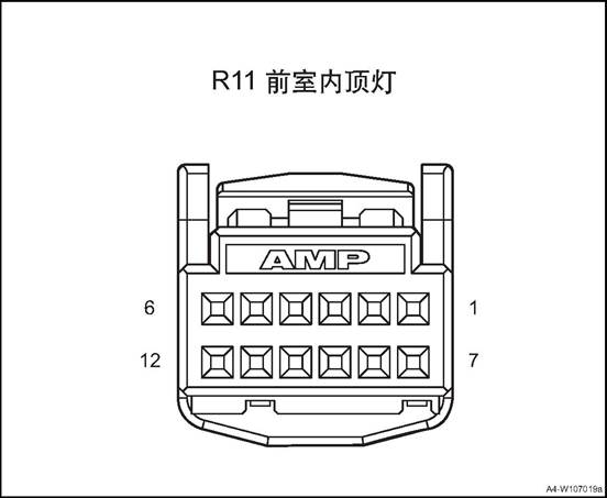
|
Connector No. |
Connector pin |
Wire Color |
Wire Diameter |
Pin Definition |
|||||
|
R11 |
1 |
Br |
0.75 |
Inner cab roof lamp power (without SOS) |
|||||
|
R11 |
2 |
Bl |
0.5 |
Sunroof up (without SOS) |
||||||
|
R11 |
3 |
Lg |
0.5 |
Sunroof down (single sunroof) |
||||||
|
R11 |
3 |
Gr |
0.5 |
Sunvisor curtain close (panoramic sunroof) |
||||||
|
R11 |
4 |
B |
0.5 |
Inner cab lamp control signal (without SOS) |
||||||
|
R11 |
5 |
- |
- |
- (without SOS) |
||||||
|
R11 |
6 |
Lg |
0.5 |
Lighting signal (without SOS) |
||||||
|
R11 |
7 |
Br/O |
0.35 |
Backlight power (without SOS) |
||||||
|
R11 |
8 |
- |
- |
- (without SOS) |
||||||
|
R11 |
9 |
Bl/G |
0.5 |
Sunroof close (single sunroof) |
||||||
|
R11 |
9 |
B/R |
0.5 |
Sunroof close (panoramic sunroof) |
||||||
|
R11 |
10 |
G/R |
0.5 |
Sunroof open (single sunroof) |
||||||
|
R11 |
10 |
Bl/O |
0.5 |
Sunroof open (panoramic sunroof) |
||||||
|
R11 |
11 |
Br |
0.5 |
Sunroof up/down signal (panoramic sunroof) |
|
|||||
|
R11 |
12 |
B |
0.5 |
GND (without SOS) |
|
|||||
Inner cab roof lamp pin diagram (with SOS)
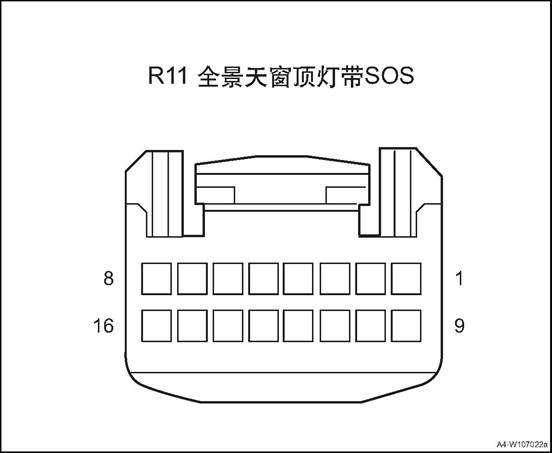
|
Connector No. |
Connector pin |
Wire Color |
Wire Diameter |
Pin Definition |
|
R11 |
1 |
Gr |
0.5 |
Signal GND |
|
R11 |
2 |
|
|
|
|
R11 |
3 |
Br |
0.75 |
Interior cab lamp power |
|
R11 |
4 |
Bl |
0.5 |
Sunvisor curtain open |
|
R11 |
5 |
Gr |
0.5 |
Sunvisor curtain close |
|
R11 |
6 |
B |
0.5 |
Inner cab lamp control |
|
R11 |
7 |
|
|
|
|
R11 |
8 |
Lg |
0.5 |
Lighting signal |
|
R11 |
9 |
R/Y |
0.5 |
SOS signal + |
|
R11 |
10 |
R/Bl |
0.5 |
SOS signal |
|
R11 |
11 |
Br/O |
0.35 |
Backlight power |
|
R11 |
12 |
|
|
|
|
R11 |
13 |
B/R |
0.5 |
Sunroof close |
|
R11 |
14 |
Bl/O |
0.5 |
Sunroof open |
|
R11 |
15 |
Br |
0.5 |
Sunroof up/down signal |
|
R11 |
16 |
B |
0.5 |
GND |
Ⅳ Front Combination Lamp Assy.
△Attention: Assembly and disassembly methods of left and right front combination lamp assembly are similar.
1. Open the engine cover
2. Disconnect the battery negative cable.
3. Remove front bumper body assembly. See front bumper body assembly
4. Remove the front combination lamp assembly
![]() 1) Disconnect front combination
lamp assembly harness connector.
1) Disconnect front combination
lamp assembly harness connector.
2) Remove the 2 bolts securing the front combination lamp assembly upper part.
![]()
3) Remove the 1 bolts securing the front combination lamp assembly lower part.
![]() 4) Remove the front combination
lamp assembly.
4) Remove the front combination
lamp assembly.
1.Confirm that all tire pressures are normal.
2.Place the vehicle and tester on the same flat surface.
3. Confirm that the vehicle is in an unloaded state except for the driver (or placing an equal weight at the driver's position).
4. Turn on the low beam.
5. Adjust the light with the adjusting screw.
1)The low beam and high beam up and down adjustment can be adjusted at one dimming point, and the height of low beam and high beam can be adjusted when adjusting; the right and left adjustment of low beam and high beam can be adjusted at one adjusting point, and the right and left height of low beam and high beam can be adjusted when adjusting If repairs were made to the front of the vehicle body and / or the front combination lamp assembly was replaced, check the light and adjust it in place with the light detector.
6. Follow the light meter until it is adjusted.
Install the front combination lamp assembly
1) Place the front combination lamp at the installation place, and insert the locating pin 1 at the wing into the sheet metal.
2) Install the 2 bolts securing the front combination lamp assembly upper part.
![]() 1.Tightening torque 3~5N·m
1.Tightening torque 3~5N·m
3) Install the 1 bolts securing the front combination lamp assembly lower part.
![]() 1.Tightening torque 3~5N·m
1.Tightening torque 3~5N·m
![]() 4) Connect front combination lamp
assembly harness connector.
4) Connect front combination lamp
assembly harness connector.
△Attention: this is a all LED front combination lamp, the whole assembly shall be replaced if any lamp malfunctions.
2. Install front bumper body assembly
3. Connect the battery negative cable.
4. Close the engine compartment cover.
1. Open the engine cover
2. Disconnect the battery negative cable.
3. Remove front roof lamp assembly
![]() 1) Open the glass box and pry up
the 2 screw covers.
1) Open the glass box and pry up
the 2 screw covers.
2) Disassemble the 2 screws that fix the front roof lamp.
3) Pry up the front roof lamp assembly.
![]() 4) Disconnect front roof lamp
assembly harness connector.
4) Disconnect front roof lamp
assembly harness connector.
5) Take down the front roof lamp assembly.
Install the front light assembly
![]() 1) Connect front roof lamp assembly
harness connector.
1) Connect front roof lamp assembly
harness connector.
2) Clip the front roof lamp assembly to the roof.
![]() 3 ) Install the 2 screws of the
front roof lamp and the 2 screw covers.
3 ) Install the 2 screws of the
front roof lamp and the 2 screw covers.
Tightening torque 1 ~ 3N · m
4) Close the glass box.
Connect the battery negative cable.
3. Close the engine compartment cover
△Attention: Assembly and disassembly methods of left and right wall lamps are similar.
1. Open the engine cover
2. Disconnect the battery negative cable.
3. Remove the left wall lamp assy.
![]() 1) Pry out the left wall lamp assy.
1) Pry out the left wall lamp assy.
2) Disconnect left wall lamp assembly harness connector.
1. Install left wall lamp assembly .
![]() 1) Connect left wall lamp assembly
harness connector.
1) Connect left wall lamp assembly
harness connector.
2) Clip the left wall lamp assembly to the roof.
2). Connect the battery negative cable.
3. Close the engine compartment cover
1. Open the engine cover
2.
Disconnect the battery negative cable.
3. Remove the logo lamp assembly.
![]() Pry out the logo lamp assembly.
Pry out the logo lamp assembly.
2) Disconnect the logo lamp harness connector and remove the logo lamp assembly.
![]()
1. Install the logo lamp assembly
![]() 1). Connect logo lamp assembly
harness connector.
1). Connect logo lamp assembly
harness connector.
![]() 2) Install the logo lamp assembly
2). Connect the battery negative cable.
2) Install the logo lamp assembly
2). Connect the battery negative cable.
3. Close the engine compartment cover
△Note Assembly and disassembly methods of left and right license plate lamps are similar.
1. Open the engine compartment cover.
2. Disconnect the battery negative cable.
3. Remove the license plate light assembly
![]() 1) Pry out the license plate lamp
assembly.
1) Pry out the license plate lamp
assembly.
![]() 2) Disconnect license plate lamp assembly
harness connector.
2) Disconnect license plate lamp assembly
harness connector.
Install license plate light assembly
![]() 1) Connect license plate lamp
assembly harness connector.
1) Connect license plate lamp
assembly harness connector.
![]() Install the license plate lamp
assembly to the tail door.
Install the license plate lamp
assembly to the tail door.
2). Connect the battery negative cable.
3. Close the engine compartment cover
△Attention: left and right side panel rear combination lamps assembly and disassembly methods are similar
1. Open the engine compartment cover.
2. Disconnect the battery negative cable.
3. Open the tailgate
4. Left side panel rear combination lamp
![]() 1) remove the trim panel of the
left side panel rear combination lamp.
1) remove the trim panel of the
left side panel rear combination lamp.
2) Disassemble the 2 fixing bolts of the left side panel rear combination lamp.
![]()
3) Take out the left side panel rear combination lamp and disconnect its wire harness connector.
![]()
1). Check whether there are scratches on the surface of the lamp shade, whether the internal structure is loose and swaying, whether the wiring harness is fixed normally, whether there are defects on the surface of the decorative frame and the aluminized area of the reflector, and whether the external identification is correct.
1. Install the left side panel rear combination lamp
1) Put the left side panel rear combination at installation place and connect its wire harness connector.
![]() △Attention: Check if the rear combination lamp is
installed in place, and the clearance between vehicle body is proper, if not in
place or inappropriate, please re-install.
△Attention: Check if the rear combination lamp is
installed in place, and the clearance between vehicle body is proper, if not in
place or inappropriate, please re-install.
2) Mount and fasten the 2 fixing bolts of the left side panel rear combination lamp.
![]() Tightening torque 1~3N·m
Tightening torque 1~3N·m
![]() 3) Install the trim panel of the
left side panel rear combination lamp.
3) Install the trim panel of the
left side panel rear combination lamp.
2. Close the tailgate
3). Connect the battery negative cable.
4. Close the engine compartment cover.
△Note: Assembly and disassembly methods of left and right tail door combination lamps are similar.
1. Open the engine compartment cover.
2. Disconnect the battery negative cable.
3. Open the tailgate
4. Disassemble tail door trim panel assembly. See “tail door trim panel assembly”
5. Remove tail door left combination lamp.
![]() 1) Disconnect the tail door
combination lamp harness connector
1) Disconnect the tail door
combination lamp harness connector
2) Remove 4 fixing nuts② of tail door left combination lamp.
3) Remove tail door left combination lamp.
1. Check whether there are scratches on the surface of the lamp shade, whether the internal structure is loose and swaying, whether the wiring harness is fixed normally, whether there are defects on the surface of the decorative frame and the aluminized area of the reflector, and whether the external identification is correct.
1. Install tail door left combination lamp.
![]() 1) Put the tail door left
combination lamp at installation position.
1) Put the tail door left
combination lamp at installation position.
2) Install 4 fixing nuts② of tail door left combination lamp.
Tightening torque 7~9N·m
3) Connect the tail door combination lamp harness connector
2. Install tail door trim panel assembly
3. Close tail door
4. Connect the battery negative cable.
5. Close the engine compartment cover
1. Open the engine cover
2. Disconnect the battery negative cable.
3. Remove the rear bumper assembly. Refer to the rear bumper assembly
4. Disassemble rear fog lamp assembly
![]() 1) Disconnect rear fog lamp
assembly harness connector.
1) Disconnect rear fog lamp
assembly harness connector.
![]() 2) Remove 5 fixing screws of rear
fog lamp assembly.
2) Remove 5 fixing screws of rear
fog lamp assembly.
3) Remove the front fog lamp assembly.
1. Check if the rear fog lamp is intact before installation.
2. Do not damage the rear fog lamp during installation.
3. After installation, check if the rear fog lamp installation is in place and whether the gap with bumper is appropriate. If it is not in place or inappropriate, reinstall it.
1. Assemble rear fog lamp assembly
![]() 1) Put the rear fog lamp assembly
at installation position.
1) Put the rear fog lamp assembly
at installation position.
2) Mount and tighten the 5 fixing screws of rear fog lamp assembly.
Tightening torque 1~3N·m
![]() 3) Connect rear fog lamp assembly harness
connector.
3) Connect rear fog lamp assembly harness
connector.
2. Install rear bumper assembly
3. Connect the battery negative cable.
4. Close the engine compartment cover.
1. Open the engine compartment cover.
2. Disconnect the battery negative cable.
3. Remove the tail door upper frame assembly. See the “tail door upper frame assembly”.
4. Remove the high mounted brake lamp assembly
![]() 1) Disconnect high mounted brake
lamp assembly harness connector.
1) Disconnect high mounted brake
lamp assembly harness connector.
2) Remove the 5 nuts fixing the high mounted brake lamp assembly.
3) Remove the high mounted brake lamp assembly
1. Install the high mounted brake lamp assembly.
1) Put the high mounted brake lamp assembly at installation position.
2) Mount and tighten the 5 nuts fixing the high mounted brake lamp assembly.
![]() Tightening torque 2~4N·m
Tightening torque 2~4N·m
1) Connect high mounted brake lamp assembly harness connector.
2. Install the tailgate upper frame assembly
3. Connect the battery negative cable.
4. Close the engine compartment cover.
There are 8 loudspeakers in the vehicle, 4 tweeters and 4 woofers, which are installed in the front door and the rear door respectively. The number of speakers differs according to configuration.
![]()
1. Front Door Woofer
2. Right Tweeter
3. Front Screen Assembly
4. Left Front Door Woofer
5. Left Tweeter
6. Microphone Assembly
7. Shark Fin Antenna
1) When the ignition switch is in “ACC”, press "PWR" button to open MP5, operate other buttons to check MP5 working state;
2) Touch the screen button "VOL" to adjust the volume and test whether the volume adjustment is normal.
3) Select AM or FM band to detect whether the station is normally searched.
4) Adjust the receiving frequency, increase or decrease 0.1MHZ for each press of FM band, and increase or decrease 9KHZ for each press of AM band.
5) Press "MEDIA" to enter the multimedia.
6) Insert the USB device to test whether the USB device is functioning properly.
Basic operation: Insert the USB with updating program, automatically pops up the updating interface.
|
No. |
Item |
Tightening torque (N · m) |
|
1 |
Shark fin antenna bolt |
5~10 |
|
2 |
Front screen assembly screw |
5~10 |
|
3 |
Front screen host assembly screw |
5~10 |
|
4 |
Microphone module assembly screw |
5~10 |
|
5 |
Tweeter screw |
3~5 |
|
6 |
Woofer screw |
3~5 |
1. The inspection may influence the device installed after sales
2. Check the components which are easily seen and contacted first,check whether there are badly or probably damaged situations.
3. If all the speakers can not work,check the parts that are easily short to ground carefully,which is benefit for solving troubles quickly.
4. If only one speaker can not work,it may caused by that the customer use the audio shielding function and shield the sound channel unintentionally and make it not work,it doesn’t belong to system trouble,refer to the user's manual of the audio system.
|
No. |
Fault symptoms |
Fault analysis |
Solutions |
Remark |
|
1 |
The LCD screen is not displayed |
The power supply switch and ignition switch are not connected |
Connect the switch |
|
|
The connecting wires are loose |
Readjust |
|||
|
The fuse is burned |
Replace new fuse |
|||
|
2 |
It can not play sound |
The system is in mute state |
Press MUTE and close mute |
|
|
The connecting wire harness of the speaker is loose |
Re-connect |
|||
|
Speaker damaged |
Replace a new speaker. |
|||
|
3 |
The audio host can not open |
Power supply fuse failure |
Replace fuse |
Refer to the “Audio host can not open” |
|
The power or grounding wire of the audio host does not work |
Repair relevant wire harness |
|||
|
Audio host failure |
Replace a new audio host |
|||
|
4 |
The radio can not search any channel |
The antenna amplifier of the radio has failure |
Replace the antenna amplifier of the radio |
|
|
Audio host failure |
Replace a new audio host |
|||
|
Radio antenna failure |
Replace an antenna |
|||
|
5 |
Navigation has no signal |
Navigation antenna failure |
Replace a navigation antenna |
|
|
Obstructions above the vehicle |
Move the vehicle to a empty ground. |
The
system is normal Replace a
new audio host Whether
accord with standard value Check the
resistance between terminal M18 of audio host harness connector and vehicle
body grounding Resistance
standard value: less than 1Ω Whether
accord with standard value Check the
power supply voltage of terminal 4 and 6 of audio host harness connector M18 Standard
value: 11 ~ 14V Check if
the fuse is blown Check for
short circuit in fuse circuit or replace fuse Fault
phenomenon: The audio host can not open No No No Yes Yes Yes Check
open circuit fault between audio host harness connector M18 and body
grounding Check
open circuit fault between terminal 4 and 6 of audio host harness connector
M18 and fuse Check
fuse FS29, FS38
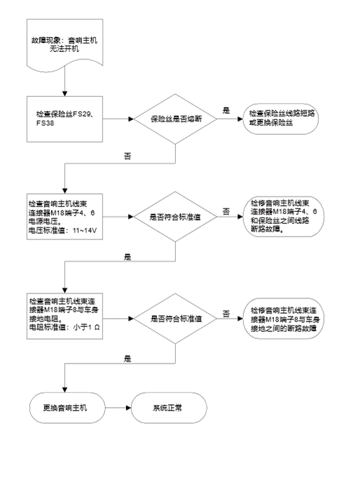
M17 MP5
screen
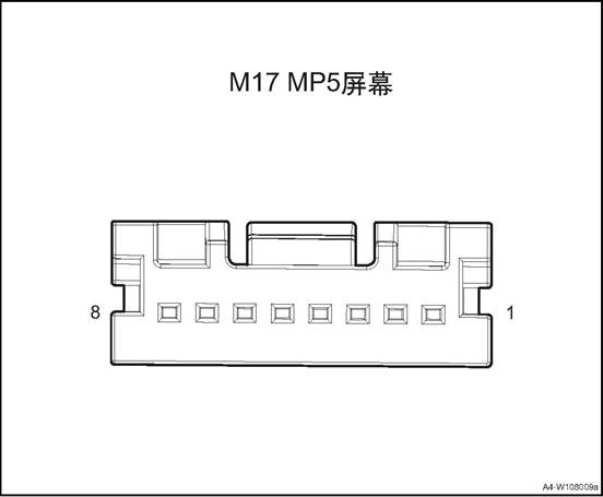
|
Connector No. |
Connector pin |
Wire Color |
Wire Diameter |
Pin Definition |
|
M17 |
1 |
R |
0.5 |
power |
|
M17 |
4 |
B |
0.5 |
GND |
![]()
![]()
|
Connector No. |
Connector pin |
Wire Color |
Wire Diameter |
Pin Definition |
|
M18 |
1 |
B |
0.35 |
backlight (-) |
|
M18 |
2 |
R |
0.5 |
Wire control ground |
|
M18 |
3 |
Bl/O |
0.5 |
Wire control signal 1 |
|
M18 |
4 |
R |
0.75 |
ACC power supply |
|
M18 |
5 |
Bl/G |
0.5 |
Wire control signal 2 |
|
M18 |
6 |
Bl/B |
0.5 |
backlight (+) |
|
M18 |
7 |
Br/O |
0.35 |
Main power B + |
|
M18 |
8 |
B |
0.75 |
GND |
![]()
![]()
|
Connector No. |
Connector pin |
Wire Color |
Wire Diameter |
Pin Definition |
|
M39 |
1 |
G |
0.5 |
Right rear speaker - |
|
M39 |
2 |
G/B |
0.5 |
Right rear speaker - |
|
M39 |
3 |
G/Y |
0.5 |
Right front speaker + |
|
M39 |
4 |
G/Bl |
0.5 |
Right front speaker - |
|
M39 |
5 |
G/O |
0.5 |
Left front speaker + |
|
M39 |
6 |
Br/R |
0.5 |
Left front speaker - |
|
M39 |
7 |
Gr/B |
0.5 |
Left rear speaker + |
|
M39 |
8 |
G/W |
0.5 |
Left rear speaker - |
![]()
![]()
|
Connector No. |
Connector pin |
Wire Color |
Wire Diameter |
Pin Definition |
|
M27 |
1 |
Gr/B |
0.5 |
Camera video ground |
|
M27 |
2 |
G/Y |
0.5 |
Camera video signal |
|
M27 |
8 |
G |
0.5 |
Camera shield ground |
|
M27 |
10 |
O |
0.5 |
CAN_H |
|
M27 |
11 |
Y |
0.5 |
CAN_L |
|
M27 |
12 |
Gr |
0.5 |
Right channel (T-box input) |
|
M27 |
13 |
R/O |
0.5 |
AUX GND |
|
M27 |
18 |
Gr |
0.35 |
MIC1 signal input |
|
M27 |
19 |
Br |
0.35 |
MIC2 signal input |
|
M27 |
20 |
Lg |
0.35 |
MIC signal shield ground |
1. Open the engine cover
2. Disconnect the battery negative cable.
3. Dismantle the right and the left A pillar upper panel assembly, refer to the “A pillar upper panel assembly”.
4. Dismantle the left and the right front doorsill guard plate assemblies, refer to the ”front doorsill guard plate assembly”.
5. Dismantle the left and the right rear doorsill guard plate assemblies, refer to the ”rear doorsill guard plate assembly”.
6. Remove B pillar lower guard assemblies. See B pillar lower guard assembly
7. Remove B pillar upper guard assembly. See B pillar upper guard assembly
8. Remove the rear seat assembly. See the rear seat assembly
9. Remove the C pillar lower guard plates and luggage compartment guard plate. Refer to the “C pillar lower guard plate” and the “luggage compartment guard plate”.
10. Remove C pillar upper guard assemblies. See C pillar upper guard assembly
11. Dismantle the sun visor assembly(left/right) . refer to the “sun visor assembly”.
12. Dismantle the front roof lamp refer to the front roof lamp
13. Remove left and right wall lamp assemblies, refer to the “left wall lamp assembly”
14. Remove the right and the left roof handles. See “side roof handle”.
15. Dismantle the roof assembly refer to the roof assembly
16. Remove the Shark fin antenna assembly
![]() 1) Disconnect the shark fin antenna
assembly wire harness connector 1.
1) Disconnect the shark fin antenna
assembly wire harness connector 1.
2) Remove the one fixing bolt 2 of the shark fin antenna assembly.
![]() 3) Remove the shark fin antenna
assembly from the roof.
3) Remove the shark fin antenna
assembly from the roof.
Install shark fin antenna assembly
![]() 1) Put the antenna at installation
position.
1) Put the antenna at installation
position.
△ Note: Ensure that the shark fin antenna assembly is in the correct direction.
![]() 2) Instlal the one fixing bolt 2 of
the shark fin antenna assembly.
2) Instlal the one fixing bolt 2 of
the shark fin antenna assembly.
Tightening torque 5 ~ 10N · m
3) Connect the shark fin antenna assembly wire harness connector 1.
2. Install the roof assembly
3. Install the left and the right side roof handles.
4. Install left and right side wall lamp assemblies
5. Install the front roof lamp assembly
6. Install the sun visor assembly
7. Install the right and the left C pillar upper guard assemblies.
8. Install the right and the left C pillar lower guard assemblies.
9. Install the rear row seat assembly
10. Install the right and the left B pillar upper guard assemblies.
11. Install the right and the left B pillar lower guard assemblies.
12. Install left rear doorsill guard plate assembly.
13. Install the front doorsill guard plate assembly.
14. Install the right and the left A column upper panel assembly
15). Connect the battery negative cable.
16. Close the engine compartment cover
1. Open the engine cover
2. Disconnect the battery negative cable.
3. Remove the central trim panel assembly of the dashboard. Refer to the central trim panel assembly.
4. Remove the right trim panel assembly of the dashboard. Refer to the right trim panel assembly.
![]() 5. Disassemble the front screen assembly.
5. Disassemble the front screen assembly.
1) Dismantle the 4 fixing screws of the front screen assembly.
![]() 2) Take out the front screen
assembly.
2) Take out the front screen
assembly.
3) Disconnect the front screen assembly wire harness connector.
1. Install the front screen assembly.
![]() 1) Put the front screen assembly at
installation position.
1) Put the front screen assembly at
installation position.
2) Connect the front screen assembly wire harness connector.
![]() 3) Mount and tighten threads 4
screws of the front screen assembly.
3) Mount and tighten threads 4
screws of the front screen assembly.
Tightening torque 5 ~ 10N · m
2. Assemble the right trim panel assembly of the dashboard.
3. Assemble the central trim panel assembly of the dashboard.
4. Connect the battery negative cable
5. Close the engine compartment cover
1. Open the engine cover
2. Disconnect the battery negative cable.
3. Remove the central trim panel assembly of the dashboard. Refer to the central trim panel assembly.
4. Remove the right trim panel assembly of the dashboard. Refer to the right trim panel assembly.
5. Remove the front screen assembly.
![]() 6. Disassemble the front screen
host assembly.
6. Disassemble the front screen
host assembly.
1) Dismantle the 4 fixing screws of the front screen host assembly.
![]() 2) Take out the front screen host
assembly.
2) Take out the front screen host
assembly.
3) Disconnect the front screen host assembly wire harness connector.
![]() 1. Install the front screen host assembly.
1. Install the front screen host assembly.
1) Connect the front screen host assembly wire harness connector.
2) Place the front screen assembly at installation place.
![]() 3) Mount and tighten 4 screws of
the front screen host assembly.
3) Mount and tighten 4 screws of
the front screen host assembly.
Tightening torque 5 ~ 10N · m
2. Install the front screen assembly.
3. Assemble the right trim panel assembly of the dashboard.
4. Assemble the central trim panel assembly of the dashboard.
5. Connect the battery negative cable
6. Close engine compartment cover
1. Open the engine cover
2. Disconnect the battery negative cable.
3. Dismantle front roof lamp, refer to the “front roof lamp”.
4. Remove the microphone module assembly.
![]() 1)Disconnect the microphone module
assembly harness connector 1.
1)Disconnect the microphone module
assembly harness connector 1.
2) Install the 4 screws fixing the microphone module assembly.
3) Remove the microphone module assembly.
1. Check the microphone module assembly.
1) Check if there is damage or crack in the installation point of the microphone module assembly.
2) If any, replace the microphone module assembly.
1. Install the microphone module assembly.
![]() 1) Put the microphone module
assembly at installation position.
1) Put the microphone module
assembly at installation position.
2) Install the 4 screws fixing the microphone module assembly.
Tightening torque 5 ~ 10N · m
3) Connect the microphone module assembly harness connector 1.
2. Install front roof lamp.
3. Connect the battery negative cable.
4. Close the engine compartment cover.
1. Open the engine cover
2. Disconnect the battery negative cable.
3. Dismantle the multi-media interface
![]() 1) Pry up the multimedia interface
assembly
1) Pry up the multimedia interface
assembly
![]() 2) Disconnect multimedia interface
assembly harness connector.
2) Disconnect multimedia interface
assembly harness connector.
1. Install the multimedia interface assembly
![]() 1) Connect multimedia interface
assembly harness connector.
1) Connect multimedia interface
assembly harness connector.
![]() 2) Install the multimedia interface
assembly
2) Install the multimedia interface
assembly
2). Connect the battery negative cable.
3. Close the engine compartment cover
1. Open the engine cover
2. Disconnect the battery negative cable.
3. Remove front door interior panel assembly see front door interior panel assembly
4. Disassemble the front door woofer
![]() 1) Disconnect the front door woofer
harness connector
1) Disconnect the front door woofer
harness connector
2) Dismantle the 2 fixing screws of front door woofer
3) Disassemble the front door woofer
1. Install the front door woofer
![]() 1) Put the front door woofer at
installation position.
1) Put the front door woofer at
installation position.
2) Mount and tighten the front door woofer 2 fixing bolts.
Tightening torque 3~5N·m
3) Connect the front door woofer harness connector
Install front door trim panel assembly
3. Connect the battery negative cable.
4. Close the engine compartment cover.
1. Open the engine cover
2. Disconnect the battery negative cable.
3. Remove front door interior panel assembly see front door interior panel assembly
4. Remove the tweeter.
![]() 1) Dismantle the 2 fixing screws of
tweeter.
1) Dismantle the 2 fixing screws of
tweeter.
2) Take down the tweeter.
1. Install the tweeter.
![]() 1) Put the tweeter at installation
position.
1) Put the tweeter at installation
position.
2) Mount and tighten the tweeter 2 fixing bolts.
Tightening torque 3~5 N·m
Install front door trim panel assembly
3. Connect the battery negative cable.
4. Close the engine compartment cover.
The horn is mounted on the front module assembly on the front of the vehicle. There is high pitch horn and low pitch horn, both controlled by the steering wheel horn switch. When the steering wheel horn button is pressed, the horn circuit is powered, causing the horn to sound.
![]()
1. High pitch horn assembly 2. Low pitch horn assembly
|
No. |
Item |
Torque (N·m) |
|
1 |
Horn fixing bolt |
4~6 |
1 Electric Horn System Diagnosis
1. Operate the horn to check the working state of the horn.
2. If the abnormal sound of the horn is quite obvious,do the following verifications
1) Check whether there is any bad contact of the terminal; Repair any bad contact
2) Check the grounding If there is an obvious bad contact,repair it
3) Ensure the fixing bolt of horn is fixed properly
4) Ensure there is no contact between horn and any others;if there is a contact,readjust the correct position of others,if it is needed,bend the horn assembly bracket.
3. Operate the horn to check whether the situation still exists If the situation still exists,ensure the sound type generated by horn:low pitch, weak pitch
1) If the sound is low and boring,it means the current is too high and the circuit must be checked,if the circuit is normal,replace the horn
2) If the sound is sharp and weak,it means the horn may have foreign material on it,dismantle the horn assembly and check any foreign material
4. Remove the foreign material and install the horn assembly
5. If no foreign material is found or can not be removed,replace the assembly
6. Operate the horn to ensure all the matters are solved
|
Step |
Measure |
Normal Result |
No |
|
1 |
Press and loosen the horn button |
When pressing the horn button, the horn honks When releasing the horn button, the horn stops honking |
Horn can’t work normally---noise abnormal |
|
Steps |
Measure |
Yes |
No |
|
1 |
Check whether the horn fuse in the engine compartment is blown. |
Turn to step 3 |
Turn to step 2 |
|
2 |
1.Pull out the horn assembly connector 2. Use the test light to connect terminal 1 and terminal 2 of the horn connector. 3. Observe the test light while pressing the horn button Whether the test light is lit. |
Turn to step 4 |
Turn to step 5 |
|
3 |
After excluding other wiring problems,replace the fuse to check whether the failure is solved |
|
Turn to step 2 |
|
4 |
Replace the horn assembly |
|
|
|
5 |
1.Re-connect the horn 2. Disconnect the horn relay 3. Use the test light to connect the relay Whether the horn can honk |
Turn to step 8 |
Turn to step 6 |
|
6 |
Check the wires between horn and replay/ground, |
Turn to step 4 |
Turn to step 7 |
|
7 |
Repair or replace the wires between horn and replay/ground,whether the failure is solved. |
|
Turn to step 4 |
|
8 |
1. Install the horn relay 2. Disconnect the wire of the air bag system 3. Remove the wire of the horn from the steering wheel 4. Use the test light to lap terminal 9 and 12 of the horn button. Whether the horn can honk? |
Turn to step 9 |
Turn to step 10 |
|
Steps |
Measure |
Yes |
No |
|
9 |
Replace the horn button |
|
|
|
10 |
Check the connecting wire between horn button and relay/ground. |
Turn to step 12 |
Turn to step 11 |
|
11 |
Repair or replace the connecting wire between horn button and relay/ground, check whether the failure is solved. |
|
Turn to step 12 |
|
12 |
Replace the horn relay |
|
|
1. Open the engine cover
2. Disconnect the battery negative cable.
3. Remove front bumper body assembly. See front bumper body assembly
4. Remove low pitch horn assembly
![]() 1) Disconnect the low pitch horn
assembly wire harness connector 1.
1) Disconnect the low pitch horn
assembly wire harness connector 1.
2) Remove the 1 mounting screw for the low pitch horn assembly
3) Take down the low pitch horn assembly.
Install the low pitch horn assembly.
![]() 1) Put the low pitch horn assembly
at installation position.
1) Put the low pitch horn assembly
at installation position.
2) Mount and tighten the 1 screw for the low pitch horn assembly
Tightening torque 4 ~ 6N · m
3) Connect the low pitch horn assembly wire harness connector 1.
2. Install front bumper body assembly
3. Connect the battery negative cable.
4. Close the engine compartment cover.
1. Open the engine cover
2. Disconnect the battery negative cable.
3. Remove front bumper body assembly. See front bumper body assembly
4. Remove high pitch horn assembly
![]() 1) Disconnect the low pitch horn
assembly wire harness connector 1.
1) Disconnect the low pitch horn
assembly wire harness connector 1.
2) Remove the 1fixing bolt of the high pitch horn assembly.
3) Take down the high pitch horn assembly
1. Install the high pitch horn assembly
1) Put the high pitch horn assembly at installation position.
![]() 2) Mount and tighten the 1 screw
for the high pitch horn assembly
2) Mount and tighten the 1 screw
for the high pitch horn assembly
Tightening torque 4 ~ 6N · m
3) Connect the high pitch horn assembly wire harness connector 1.
2. Install front bumper body assembly
3. Connect the battery negative cable.
4. Close the engine compartment cover.
1. Sunroof front water outlet pipe assembly
2. Sunroof assembly
3. Sunroof rear water outlet pipe assembly
The sunroof of car can effectively make the car air circulation, increase the fresh air into, driving for a healthy and comfortable enjoyment. At the same time can also make our vision broaden.
The function of sunroof: 1. Ventilation
Sunroof have changed the traditional way of ventilation, sunroof is based on the principle of negative pressure ventilation. It draws out the dirty air in the car by the negative pressure formed by the rapid flow of airflow on the roof when the car is driving, so as to achieve the purpose of air exchange and keep the fresh air in the carriage all the time.
2. Defogging: The use of sunroof defogging is a quick way to defog. Especially in summer and autumn, with more rain and humidity. If the windows are closed tightly during driving, the temperature difference
between inside and outside the car will be increased, which makes the front windshield easy to form fog. Although most cars are equipped with anti-fog device, but sometimes the effect is not so obvious. At this time,
you only need to open the roof window to the rear tilting ventilation position, which can easily eliminate the fog of the front windshield and ensure the driving safety. The use of sunroof ventilation, neither the car outside the dirty dirty environment, do not have to worry about the rain was blown into the car.
3.energy conservation
In the hot summer, the car in the sun for an hour, the car temperature can easily reach about 70 ℃. Open the door, a heat wave will be blowing, for many people, will choose to open the car air-conditioning to reduce the temperature inside the car. In fact, just open the skylight, the use of vehicles in the process of forming the roof negative pressure out of the hot air can achieve the purpose of rapid ventilation cooling, the use of this method than the use of automotive air conditioning cooling 2 to 3 times faster, but also Save gasoline
Louver tilted open / closed:
Ignition switch is placed ON file, touch the button UP, sunroof glass tilt to fully open position and automatically stop. During the tilting operation, press any key, the skylight will stop in the current position. If you keep pressing the button,the sunroof will also tilt completely but will stop once you release in in the midway.
Hold down the button DOWN, you can close the sunroof, the sunroof does not have anti-pinch function. Touch the button DOWN, can not automatically close the sunroof. Skylight slide open / closed:
When the ignition switch is in the ON position, touch the OPEB button and the louvre will move backward until it stops automatically after the maximum position. Half-way press any key, skylight will stop in the current location. Continuously press the key, sunroof can slide backward to fully open, but release the button halfway, the sunroof will stop running. Skylight glass sliding back open, will lead to sunroof synchronized open.
Keep pressing the CLOSE button to close the sunroof. But let go of the button halfway, the sunroof will stop running. Touch the CLOSE button, the window can not be closed automatically. Sunroof sun visor can only be closed manually.
When the sliding window glass is closed, when the glass hits an obstacle, it will automatically return to the movement and stop at the maximum position. This function is not available in tilting close mode.
|
No. |
Item |
Torque (N·m) |
|
1 |
Sunroof fixing nut |
4~7 |
|
No. |
Fault symptoms |
Fault analysis |
Solutions |
Remark |
|
1 |
Sunroof leaking |
Drainage Dust deposition |
Remove the dust in the drain pipe |
|
|
Drainage blocked |
Blow to drain to remove dirt |
|||
|
Drainage pipe fracture or detachment, pipe clip damage |
Check piping and flange contact |
|||
|
Roof seal aging |
Change the roof seal |
|||
|
Skylight glass and the body gap is too large and seal assembly is not correct |
Adjust the window glass |
|||
|
2 |
There is wind noise around the skylight |
Deflector loose or deformation, the gap does not meet the requirements |
Tighten, adjust or replace |
|
|
3 |
Roof sun visor noise when moving |
There are foreign objects in the rail |
Check drive cable and rail for foreign objects |
|
|
Rail and sun visor loose |
Tighten, adjust or replace |
|||
|
4 |
The motor is working but the skylight can not move or move out of position |
There are foreign objects in the rail |
Check drive cable and rail for foreign objects |
|
|
Incorrect engagement of motor pinion with drive cable |
Check whether the motor is loose and the pinion is damaged |
|||
|
The motor's clutch slip force is reduced |
Adjustment or replacement |
|||
|
Due to improper adjustment of the skylight, skidding caused by sliding or skylights and drive cables, seals and other interference between the increase |
Adjustment or replacement |
|||
|
5 |
Motor running noise |
Incorrect engagement of motor pinion with drive cable |
Inspect the pinion and re-tighten the motor |
|
|
Motor pinion bearing worn or damaged |
Replace the motor |
|||
|
Drive cable worn or deformed |
Replace |
1. When the sunroof is closed, push the sunroof glass plate with both hands inside the vehicle to check if the glass plate mounting bolts are loose. If the glass mounting bolts are loose, it may cause the glass to move up and down. If loose, the bolts should be tightened and guaranteed to be within the torque range.
2. Open the sunroof glass plate completely and check if the drain groove in the left and right guide rails is sticky with impurities and dust. If so, use a clean, soft cloth to gently rub the dirt and dust on the sunroof rails.
3. Open and close the sunroof to check if the glass plate is stuck during operation. If this happens, please apply a proper amount of grease or a lubricant that does not easily absorb dust after cleaning the rail groove, and move the glass plate again to make it fully lubricated.
4. When the sunroof is closed, the sun visor is pushed and pulled in the car to check whether it is stuck or not. If this is the case, push the sun visor to the maximum open position, and after cleaning the rail groove, apply a proper amount of grease or a lubricant that does not easily absorb dust, and move the sun visor again to fully lubricate it.
5. If excessive grease is used, wipe off excess grease with a soft cloth to avoid contaminating the vehicle interior components.
6. Open and close the sunroof again and check the running status.
7. Move the sunroof to the fully open position, use a wet sponge to clean the rear end of the glass plate and the left and right edge seals to remove dust, dust and other debris.
8. Move the sunroof to the fully open position, use a wet sponge to clean the rear end of the glass plate and the left and right edge seals to remove dust, dust and other debris.
1. Open the engine cover
2. Disconnect the battery negative cable.
3. Dismantle the right and the left A pillar upper panel assembly, refer to the “A pillar upper panel assembly”.
4. Dismantle the left and the right front doorsill guard plate assemblies, refer to the ”front doorsill guard plate assembly”.
5. Dismantle the left and the right rear doorsill guard plate assemblies, refer to the ”rear doorsill guard plate assembly”.
6. Remove B pillar lower guard assemblies. See B pillar lower guard assembly
7. Remove B pillar upper guard assembly. See B pillar upper guard assembly
8. Remove the rear seat assembly. See the rear seat assembly
9. Remove the C pillar lower guard plates and luggage compartment guard plate. Refer to the “C pillar lower guard plate” and the “luggage compartment guard plate”.
10. Remove C pillar upper guard assemblies. See C pillar upper guard assembly
11. Dismantle the sun visor assembly(left/right) . refer to the “sun visor assembly”.
12. Dismantle the front roof lamp refer to the front roof lamp
13. Remove left and right wall lamp assemblies, refer to the “left wall lamp assembly”
14. Remove the right and the left roof handles. See “side roof handle”.
15. Dismantle the roof assembly refer to the roof assembly
16. Dismantle sunroof assembly
1) Disconnect the sunroof front water outlet pipe assembly from the sunroof assembly.
![]()
2) Disconnect the sunroof rear water outlet pipe assembly from the sunroof assembly.
![]()
![]() 3) Disconnect the sunroof assembly
wire harness connector 1.
3) Disconnect the sunroof assembly
wire harness connector 1.
4) Remove the 3 fixing nuts of the sunroof assembly rear part.
![]() 5) Remove the 3 nuts fixing the
front part of the sunroof assembly.
5) Remove the 3 nuts fixing the
front part of the sunroof assembly.
![]() 6) Remove the 3 fixing nuts on each
side of the sunroof assembly.
6) Remove the 3 fixing nuts on each
side of the sunroof assembly.
7) Take off the sunroof assembly.
Install the sunroof assembly
1) Put the sunroof assembly at installation position.
2) Install and tighten the 3 fixing nuts on each side of the sunroof assembly.
![]() Tightening torque 4 ~ 7N · m
Tightening torque 4 ~ 7N · m
3) Install and tighten the 3 fixing bolts of the sunroof assembly front part.
![]() Tightening torque 4 ~ 7N · m
Tightening torque 4 ~ 7N · m
![]() 4) Install and tighten the 3 fixing
nuts of the sunroof assembly rear part.
4) Install and tighten the 3 fixing
nuts of the sunroof assembly rear part.
Tightening torque 4 ~ 7N · m
5) Connect the sunroof assembly wire harness connector 1.
![]() 6) Connect the sunroof front water
outlet pipe to the sunroof assembly.
6) Connect the sunroof front water
outlet pipe to the sunroof assembly.
![]() 7) Connect the sunroof rear water
outlet pipe to the sunroof assembly.
7) Connect the sunroof rear water
outlet pipe to the sunroof assembly.
△Caution After the installation, perform a water spray test to check if water seeps to confirm that the installation is correct.
Install ceiling assembly
3. Install the left and the right side roof handles.
4. Install left and right side wall lamp assemblies
5. Install the front roof lamp assembly
6. Install the sun visor assembly
7. Install the right and the left C pillar upper guard assemblies.
8. Install the right and the left C pillar lower guard assemblies.
9. Install the rear row seat assembly
10. Install the right and the left B pillar upper guard assemblies.
11. Install the right and the left B pillar lower guard assemblies.
12. Install left rear doorsill guard plate assembly.
13. Install the front doorsill guard plate assembly.
14. Install the right and the left A column upper panel assembly
15). Connect the battery negative cable.
16. Close the engine compartment cover
1. Open the engine cover
2. Disconnect the battery negative cable.
3. Dismantle the right and the left A pillar upper panel assembly, refer to the “A pillar upper panel assembly”.
4. Dismantle the left and the right front doorsill guard plate assemblies, refer to the ”front doorsill guard plate assembly”.
5. Dismantle the left and the right rear doorsill guard plate assemblies, refer to the ”rear doorsill guard plate assembly”.
6. Remove B pillar lower guard assemblies. See B pillar lower guard assembly
7. Remove B pillar upper guard assembly. See B pillar upper guard assembly
8. Remove the rear seat assembly. See the rear seat assembly
9. Remove the C pillar lower guard plates and luggage compartment guard plate. Refer to the “C pillar lower guard plate” and the “luggage compartment guard plate”.
10. Remove C pillar upper guard assemblies. See C pillar upper guard assembly
11. Dismantle the sun visor assembly(left/right) . refer to the “sun visor assembly”.
12. Dismantle the front roof lamp refer to the front roof lamp
13. Remove left and right wall lamp assemblies, refer to the “left wall lamp assembly”
14. Remove the right and the left roof handles. See “side roof handle”.
15. Dismantle the roof assembly refer to the roof assembly
16. Remove sunroof front water outlet pipe assembly
1) Disconnect the sunroof front water outlet pipe assembly from the sunroof assembly.
![]()
2) Disconnect the sunroof front water outlet pipe assembly from the vehicle body.
![]() 3) Pull out the sunroof front water
outlet pipe assembly from the buckles.
3) Pull out the sunroof front water
outlet pipe assembly from the buckles.
1. Install the sunroof front water outlet pipe assembly.
1) Fix the sunroof front water outlet pipe assembly on the bodywork sheet metal with buckles.
![]() 2) Connect the sunroof front water
outlet pipe assembly to the vehicle body.
2) Connect the sunroof front water
outlet pipe assembly to the vehicle body.
![]() 3) Connect the sunroof front water
outlet pipe to the sunroof assembly.
3) Connect the sunroof front water
outlet pipe to the sunroof assembly.
Install ceiling assembly
3. Install the left and the right side roof handles.
4. Install left and right side wall lamp assemblies
5. Install the front roof lamp assembly
6. Install the sun visor assembly
7. Install the right and the left C pillar upper guard assemblies.
8. Install the right and the left C pillar lower guard assemblies.
9. Install the rear row seat assembly
10. Install the right and the left B pillar upper guard assemblies.
11. Install the right and the left B pillar lower guard assemblies.
12. Install left rear doorsill guard plate assembly.
13. Install the front doorsill guard plate assembly.
14. Install the right and the left A column upper panel assembly
15). Connect the battery negative cable.
16. Close the engine compartment cover
1. Open the engine cover
2. Disconnect the battery negative cable.
3. Dismantle the right and the left A pillar upper panel assembly, refer to the “A pillar upper panel assembly”.
4. Dismantle the left and the right front doorsill guard plate assemblies, refer to the ”front doorsill guard plate assembly”.
5. Dismantle the left and the right rear doorsill guard plate assemblies, refer to the ”rear doorsill guard plate assembly”.
6. Remove B pillar lower guard assemblies. See B pillar lower guard assembly
7. Remove B pillar upper guard assembly. See B pillar upper guard assembly
8. Remove the rear seat assembly. See the rear seat assembly
9. Remove the C pillar lower guard plates and luggage compartment guard plate. Refer to the “C pillar lower guard plate” and the “luggage compartment guard plate”.
10. Remove C pillar upper guard assemblies. See C pillar upper guard assembly
11. Dismantle the sun visor assembly(left/right) . refer to the “sun visor assembly”.
12. Dismantle the front roof lamp refer to the front roof lamp
13. Remove left and right wall lamp assemblies, refer to the “left wall lamp assembly”
14. Remove the right and the left roof handles. See “side roof handle”.
15. Dismantle the roof assembly refer to the roof assembly
16. Remove the sunroof front water outlet pipe assembly.
![]() 1) Disconnect the sunroof rear
water outlet pipe assembly from the sunroof assembly.
1) Disconnect the sunroof rear
water outlet pipe assembly from the sunroof assembly.
2) Disconnect the sunroof rear water outlet pipe assembly from the vehicle body.
![]() 3) Pull out the sunroof rear water
outlet pipe assembly from the buckles.
3) Pull out the sunroof rear water
outlet pipe assembly from the buckles.
1. Install the sunroof rear water outlet pipe assembly.
1) Fix the sunroof rear water outlet pipe assembly on the bodywork sheet metal with buckles.
2) Connect the sunroof rear water outlet pipe assembly to the vehicle body.
![]()
![]() 3) Connect the sunroof rear water
outlet pipe to the sunroof assembly.
3) Connect the sunroof rear water
outlet pipe to the sunroof assembly.
2. Install the roof assembly
3. Install the left and the right side roof handles.
4. Install left and right side wall lamp assemblies
5. Install the front roof lamp assembly
6. Install the sun visor assembly
7. Install the right and the left C pillar upper guard assemblies.
8. Install the right and the left C pillar lower guard assemblies.
9. Install the rear row seat assembly
10. Install the right and the left B pillar upper guard assemblies.
11. Install the right and the left B pillar lower guard assemblies.
12. Install left rear doorsill guard plate assembly.
13. Install the front doorsill guard plate assembly.
14. Install the right and the left A column upper panel assembly
15). Connect the battery negative cable.
16. Close the engine compartment cover
1. Condenser assembly
2. Pipeline & expansion valve assy.
3. Heater water pipe
4. Front defroster air duct assy.
5. Front face mode air duct assy.
6. Rear row face mode air duct assy.
7. Rear row feet mode air duct
8. Temperature control motor
9. Throttle Motor
10. A/C control box assy. (electric)
The vehicle model uses electric control A/C system. The A/C condenser uses supper-cooling type which improve the cooling performance. To help defrosting, the external cycle mode is automatically switched to when mixing and defrosting modes are selected. Condenser fan is divided to low and high phase control according to the vehicle speed, cooling water temperature, A/C refrigerant pressure. The increase of the blower wind value and the improvement of air mixture ability can enhance the cooling and warming performance.
The A/C adopts electric control mode, and the MP5 is integrated with rear defrosting switch (including rearview mirror heating function), the temperature regulation, internal and external circulation and air outlet mode are all controlled by servo motor.
A/C host assembly consists of blower, expansion valve, evaporator, heater and shell. Blower inhaled outside air, the air flows through the evaporator, heater, etc. into the car, in order to achieve the normal operation of air conditioning.
Blower
Blower is the composition of the motor and fan, the use of air intake and exhaust door motor switch internal and external air mode. And inhale indoor air or outside air. The suction port damper motor function is achieved through the controller's internal and external air buttons. In the internal circulation mode, air is supplied from two air inlets on the side;
and air is taken in through the filter on the front cover of the vehicle in the external circulation mode. At this time, the use of air blower suction, and heat exchange through the evaporator, the cooled air into the car.
Adjuster module
Blower motor speed is adjusted according to the change of output voltage.
Inner and outer cycle model throttle motor
Installed in the blower assembly, by the automatic air conditioning control buttons on the inside and outside the cycle, driven by internal and external circulation damper to achieve the conversion of the intake mode.
Blower motor
Utilize the power of the vehicle, rotate the fan to form the air volume needed for the air conditioning system.
Evaporator temperature sensor
![]() Perception of the evaporator core temperature, passed
to the controller to prevent the evaporator ice. There is negative temperature
coefficient thermistor inside the sensor, so resistance decreases as
temperature decreases and resistance decreases as temperature increases.
Evaporator temperature sensor parameter chart
Perception of the evaporator core temperature, passed
to the controller to prevent the evaporator ice. There is negative temperature
coefficient thermistor inside the sensor, so resistance decreases as
temperature decreases and resistance decreases as temperature increases.
Evaporator temperature sensor parameter chart
Evaporator and heater
![]() After the air sent by the blower is
cooled down by the evaporator, a part of the air passing through the evaporator
is sent to the heater core according to the degree of opening and closing of
the temperature control damper, and the rest is sent to the upper part of the
heater case. In order to control room temperature control and air mixing, the
air passing through the heater core and the air flowing into the upper portion
of the heater housing are mixed at the rear of the heater housing. This mixed
air through the mode door motor role, was sent to the required outlet, play a
vehicle interior temperature control and defrost/defogging function. Heater
assembly adjust the air mixture, temperature control, the direction of the air.
After the air sent by the blower is
cooled down by the evaporator, a part of the air passing through the evaporator
is sent to the heater core according to the degree of opening and closing of
the temperature control damper, and the rest is sent to the upper part of the
heater case. In order to control room temperature control and air mixing, the
air passing through the heater core and the air flowing into the upper portion
of the heater housing are mixed at the rear of the heater housing. This mixed
air through the mode door motor role, was sent to the required outlet, play a
vehicle interior temperature control and defrost/defogging function. Heater
assembly adjust the air mixture, temperature control, the direction of the air.
Throttle Motor
Assembled on the left side of the heater housing, controlled by the signal from the air conditioner panel (ETC) mode switch, activates the position of the miniature motor adjustment mode damper inside the damper motor. When the motor starts to change the voltage difference is reflected in the ETC, ETC judges the feedback signal. When the throttle reaches the required position, the motor will stop working.
Temperature control throttle motor
Installed in the right part of the evaporator housing, controlled by the operation signal of the temperature control knob of the A/C control module, and starts the position of the small motor to adjust the temperature control damper. When the motor starts, the varying motor voltage difference is reflected to the A/C controller, and the A/C controller judges the reflected signal. When the throttle reaches the required position, the motor will stop working.
The compressor from the high temperature and pressure gas refrigerant at room temperature cooling. The cooling of the condenser depends on the forced air flow of the traveling wind and the fan. The condenser of this model is a parallel flow, combined with the drying bottle. Cooling performance is improved by subcooling, reducing the amount of refrigerant required by the system and reducing the number of components in combination with the drying bottle. System pollution, the past is to replace the drying bottle, but this model to dry the lower part of the lid after the separation of the desiccant can be replaced.
The three-way pressure switch is to add the middle pressure switch in the previous A/C two-way pressure switch; when the system pressure increase, the middle pressure switch activate and send the signal to engine control unit. In this case, the water tank fan and the condensing fan are in a high-speed state, thereby preventing the performance drop caused by the pressure increase. And can protect the pressure (high pressure / low pressure) abnormal air conditioning system.
Fault
phenomenon: The audio host can not open Low
temperature low pressure gas Low
temperature low pressure liquid High
temperature high pressure liquid High
temperature high pressure gas Receiver
drier Absorb
moisture contained in refrigerant, store refrigerant Compressor The low
temperature and low pressure liquid refrigerant is converted into high
temperature and high pressure gas and sent to the radiator by using the
working wheel of engine, which is controlled by clutch. Clutch
controlling organization Expansion
valve Rapidly
expand refrigerant and convert to low temperature and low pressure liquid Blower Send air
to evaporator and cool air into the car Evaporator In the
process of turning mist-like refrigerant into gas, blower is used to absorb
heat from the air through the evaporator (the ambient temperature drops) Condenser Vehicle
front-end installation, convert gaseous refrigerant into high-temperature
and high-pressure liquid refrigerant
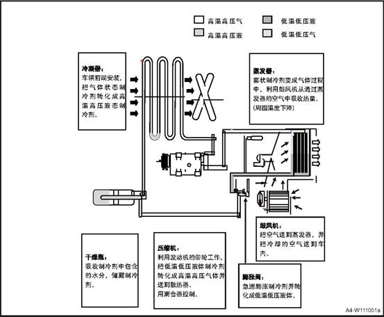
|
Item |
Parameter |
|
Refrigerant filling amount |
480±20g |
|
No. |
Item |
Torque (N·m) |
|
1 |
Standard part on the pipeline |
Lack of refrigerant |
5 A/C system control module program
After the replacement of the A/C control module, if the A/C control function is out of order or the A/C air temperature is out of order, the control module shall be reprogrammed and identified Basic operation: software update.
△ Warning The following precautions must be observed when inspecting and repairing the air conditioning system. Failure to do so may result in damage to the vehicle and personal injury.
Refrigerants have a low freezing point and high volatility. Therefore, gloves and glasses must be used to prevent chilblains and blindness caused by contact with the skin.
If the refrigerant splashed into the eyes or contact with the skin, rinse the contact area immediately with water and must be treated with ophthalmology and dermatology. Do not rub your eyes with your hand or handkerchief.
Ventilation must be performed at the site when performing refrigerant-related operations. Refrigerant in a closed place a lot of discharge, can lead to hypoxia.
Refrigerant discharge allowance: 1000ppm (4184mg / m²)
Excessive discharge can cause heart and cardiovascular system, abnormal or allergic immune system; respiratory system abnormalities or skin diseases.
When performing refrigerant-related operations, there should be no foreign matter such as moisture and dust in the surrounding environment. The flow of foreign materials into the air-conditioning system will be detrimental to the system.
Gas leak detectors are required for refrigerant-related operations. R-134a Refrigerants contact with hot objects can produce harmful gases, so pay attention to prevent leakage.
The vehicle air-conditioning system must use R-134a refrigerant. System components can be adversely affected by the use of other refrigerants.
R-134a refrigerant and R-12 refrigerant can not be compatible, so a very small amount can not be mixed.
Special attention should be paid to the fact that there is no ignition or ignition possible around the vehicle when operating in relation to the refrigerant, and the exposure of the refrigerant tank to the heat source can cause an explosion.
The R134a container is under high pressure and must not be left in a hot environment. And to check whether the storage temperature is below 52 ℃.
Air-conditioning components In order to prevent sewage, dust, moisture inflow, the general use of dust cover. Dust cover should be removed before operation and sealed after operation.
Compared with R-134a, synthetic oil (PAG) refrigerant oil absorbs moisture more easily than R-12, absorbing 10 times more oil than mineral oil (MINERAL). Excessive moisture affects the compressor, lubrication and durability.
The impact of moisture on the air conditioning system is very bad, so it is best to avoid rainy days operation.
Air-conditioning system and then install the O-ring seal must be coated with frozen oil, especially the bolt-type connection parts manually installed before using two wrenches assembly.
When assembling the flange connection part, the nut and the bolt should be connected while pushing the pipe lightly.
Air-conditioning installation, the use of more than the specified torque assembly or O-ring clamping force is too large, it will lead to refrigerant leakage, so to be in accordance with the provisions of the operation.
Hose can not be distorted.
Never completely separate the air conditioning system until it has been completely recovered. If the separation before recovery, the system pressure under the influence of refrigerant and refrigerant discharge, will pollute the surrounding environment.
When replacing air-conditioning components, you must add refrigerant oil (Model: PAG) when filling refrigerant. Refrigerant oil adding volume chart
|
Replace the pipeline |
30cc |
Replace the evaporator |
30cc |
|
Replace the condenser |
30cc |
- |
- |
When replacing the compressor, subtract the amount of refrigerant oil discharged from the old compressor from the specified amount (single-steam compressor 150g, double-steam compressor 220g) and the result is the amount of frozen oil that needs to be discharged from the new compressor. Specified Quantity - Amount of Refrigerant Expelled in Old Compressor = Amount of Refrigerant Expelled in New Compressor.
△Attention Do not discharge more than 50ml of oil from the new compressor even if there is no discharge from the disassembled compressor.
|
DTC |
DTC Number |
DTC description |
Maintenance advice |
|
B160015 |
0x960015 |
Short/open circuit of internal temperature sensor |
1) Check internal sensor wiring harness 2) Replace internal sensor |
|
B160315 |
0x960315 |
External temperature sensor short circuit or open circuit |
1) Check external sensor wiring harness 2) Replace external sensor |
|
B160415 |
0x960415 |
Evaporator temperature sensor short circuit or open circuit |
1) Check evaporator temperature sensor wiring harnes 2) Replace evaporator temperature sensor |
|
B160515 |
0x960515 |
Mode motor short circuit or open circuit |
1) Check mode motor wiring harness 2) Replace mode motor |
|
B160697 |
0x960697 |
Mode motor is stuck |
1) Check mode motor wiring harness 2) Replace mode motor |
|
B160715 |
0x960715 |
Temperature motor short circuit or open circuit |
1) Check temperature motor wiring harness 2) Replace temperature motor |
|
B160897 |
0x960897 |
Temperature motor is stuck |
1) Check temperature motor wiring harness 2) Replace temperature motor |
|
B160915 |
0x960915 |
Inner and outer circulation motor short circuit or open circuit |
1) Check inner and outer circulation motor wiring harness 2) Replace inner and outer circulation motor |
|
B160A97 |
0x960A97 |
Internal and external circulation motor is stuck |
1) Check inner and outer circulation motor wiring harness 2) Replace inner and outer circulation motor |
|
B16009C |
0x96009C |
Blower failure |
1) Check blower wiring harness 2) Replace blower or speed regulating module |
|
B100117 |
0x900117 |
ECU voltage too high |
Key OFF/ON. Wait for 5s. If failure exists, check the battery |
|
B100216 |
0x900216 |
ECU voltage too low |
Key OFF/ON. Wait for 5s. If failure exists, check the battery |
|
U014087 |
0xC14087 |
BCM communication lost |
Replace the BCM |
|
U007388 |
0xC07388 |
CAN Bus off error |
1) Check CAN BUS short circuiter 2) Key OFF/ON. Wait for 30s |
|
U018787 |
0xC18787 |
MP5 communication loss |
1) Check CAN communication wiring harness 2) Replace MP5. |
|
No. |
Fault symptoms |
Fault analysis |
Solutions |
|
1 |
Air-conditioning system without refrigerant |
There is a leak in the system |
Visual examination: 1. Observe the connection parts, check for grease which suggests leakage. You can use soapy water painted on suspicious sites, to see if there are bubbles; 2.Observe the abnormal fault of each component, and scratch, flatten and bump on the surface of condenser and evaporator core body; |
|
Use the vacuum method to hear whether there is a "beep" sound, if there is that sound, it indicates a leakage here; |
|||
|
Check with the instrument: 1. Electronic leak detector, high sensitivity 2. Dye tracing leak detection; |
|||
|
2 |
The amount of refrigerant oil in the system is not proper. |
Replace the system components, in accordance with the provisions of supplement or reduce |
1. First confirm the specifications of refrigeration oil, it can not be mixed; General specifications: PAG; 2. After the recovery of refrigerant: add about 30g of frozen oil; 3. Replace the compressor, pour out all the frozen oil in the compressor and add the same oil as in the replaced compressor; 4. Replace the pipe: add about 30g of frozen oil; 5. Replace the condenser: add about 60g of frozen oil; 6. Replace the evaporator: add about 50g of frozen oil; 7. Replace the receiver drier: add about 10g of frozen oil; |
|
3 |
Abnormal air volume |
No wind from A/C |
Circuit Malfunction 1. Check if the motor circuit and the connector is loosen; 2. Fuse off or damaged, replaced; 3. Relay damage, replace the relay; |
|
Mechanical failure 1. Motor damaged, replace it; 2. Temperature throttle damaged, unable to adjust the throttle to the refrigeration state. Replace it; 3. Controller damaged, replace it; 4. Speed control module damaged, replace it; |
|||
|
Air volume is smaller than normal |
1. Insufficient voltage, check the power supply battery 2. If the air duct is stuck or if the grille is fully opened 3. Check if the face-blow wind has leakage 4. Adjuster module faults, replace it 5. If the wind resistance of the air filter is too big, or there is dust or foreign materials blockage. 6. Motor reversely rotates, adjust the positive and negative terminal of the connector |
|
No. |
Fault symptoms |
Fault analysis |
Solutions |
|
4 |
Not cooling |
System without refrigerant |
Pressure gauge test, see "refrigerant leak" inspection; |
|
No wind |
See "air volume is not normal" check |
||
|
Compressor doesn’t work |
Electromagnetic wave not work 1. The fuse is blown, replace it 2. Connector loosen or damage in the circuit, check the wire harness and replace. 3. Relay is burnt, replace it. 4. The clutch is burnt, disassemble the clutch assembly, repair or replace it. |
||
|
Drive belt broken, replace it. |
|||
|
Signal not smooth; 1. Pressure switch damaged, no pressure signal; short signal detection, damaged, replace it; 2. ECU faults, check and repair; |
|||
|
Compressor inner broken, replace it; |
|||
|
5 |
Bad cooling performance |
Refrigerant not enough |
1. Check if the pressure is in the normal range; if it lacks refrigerant, add or refill 2. If the system has small leakage, do the leakage check. |
|
Too much refrigerant oil |
Exhaust the excessive refrigerant oil and add the required refrigerant oil volume. |
||
|
Compressor works abnormally |
Compressor belt or clutch slips |
||
|
Wind is too weak |
See "air volume is not normal" check |
||
|
Abnormal pressure |
High pressure below normal value, low pressure below normal value: 1.The expansion valve is stuck, clear the block matter. 2. Expansion valve opening insufficient, adjust the expansion valve or replace it; 3. Insufficient refrigerant, add refrigerant. |
||
|
High pressure and low pressure is higher than the normal value. 1. Condenser heat exchange is not good, check condensing fan air flow, fault replacement; 2. Too much refrigerant, release some refrigerant. |
|||
|
High pressure is lower than the normal value, the low pressure is higher than the normal value. 1. Compressor failure, lack of capacity, need to be replaced; 2. Insufficient refrigerant, add or fill. |
|||
|
High pressure is higher than the normal value, the low pressure is lower than the normal value: Impurities in the system causes blockage |
|||
|
6 |
Air-conditioning system without heating |
Core without hot water |
Warm wind water pipe stuck, clear the stuck materials. |
|
Water valve damages, the hot water can not recycle, replace it. |
|||
|
The water outlet position is not correct, so that the water does not enter circulation; it needs to be checked and maintained |
|||
|
No wind |
See "air volume is not normal" check |
||
|
Control malfunction |
The controller temperature adjustment is damaged, the temperature throttle cannot be adjusted to the maximum heating, in this case the controller should be replaced. |
||
|
7 |
Poor Heating |
Insufficient hot water circulation |
Check if engine water supply is insufficient, or the engine malfunctions. |
|
Water flow inside the heat exchanger not smooth |
Eliminate internal blockages, or replace the heat exchanger. |
||
|
Small outlet wind |
See "air volume is not normal" check |
||
|
Mode throttle is not correct |
Temperature throttle rotation is not in place, causing a mixture of hot and cold air. |
||
|
8 |
Abnormal sound in A/C system |
The compressor has abnormal sound |
Turn on the A/C and the compressor starts to work, check if the clutch has friction noise, if it has abnormal sound, replace the compressor. |
|
Expansion valve abnormal sound |
After turn on the air conditioning, check if the expansion valve position has flowing chirps sound, if so, adjust or replace the expansion valve. |
||
|
Throttle mechanism has abnormal sound |
Check whether there is resistance when adjusting the throttle mechanism, and whether there is "tick" or "cluck" sound; if there is such a phenomenon, apply lubricating oil to the throttle mechanism or replace the mechanism parts; |
||
|
The blower has abnormal sound |
Blower volute has abnormal sound 1. If there is a "boom" sound, confirm whether the motor reverses; if so, adjust the connector and circuit; 2. If there is squeak or sizzle sound, it means the motor is damaged, replace the motor; 3. If there is a "pop" sound, check the volute for foreign body, if so, remove it.. |
||
|
Check if the blower is tightly assembled |
|||
|
Heater exchanger core has water sound |
1. Press the accelerator at idle state (compressor not open) until the condensing fan rotates at high speed; 2. Continue to press accelerator and keep engine rotation speed>5000 rpm for one minute; 3. Check if there is water sound at idle or rapid accelerating state If so, repeat step 2 until there is no sound of water flow. |
||
|
9 |
A/C system has abnormal smell |
Filter has mildew |
Remove the filter, check if the surface has any serious pollution and replace it timely. |
|
Radiator surface has pollution |
Check if the evaporator and heater surface contains grease, if so, it need to be replaced or cleaned. |
||
|
Poor condensate drainage |
Poor condensate drainage causes water in the exchanger, the water deteriorates. The outlet position should be changed. |
3 Refrigerant Adding and Discharging
![]() 1. Install refrigerant filler.
1. Install refrigerant filler.
1) Turn off the manual valve on both ends of the refrigerant filler.
2) The filler tube of the refrigerant filler should be mounted on the connection part. Connect the low-pressure pipe to the low-pressure pipe orifice, and the high-pressure pipe to the high-pressure pipe orifice, and tighten the nuts by hand.
2. Refrigerant discharging operation
1) Connect the refrigerant filler to system.
2) Place a clean rag on the central hose opening.
3) Gradually open the high pressure manual valve and discharge the refrigerant.
△Attention: If the discharging speed is too high, compressor refrigeration oil will be discharged from the system.
4) Check the rag for trace of refrigerant oil, and close the manual valve slightly when there is a trace.
5) When the Instrument scale drops to 3.5kg / c ㎡, slowly open the low-pressure manual valve.
6) In order to reduce system pressure, high pressure and low pressure manual valves should be slowly opened until the scale shows 0kg / c ㎡.
![]() 3. Refrigeration system vacuum operation
3. Refrigeration system vacuum operation
△Attention The system must be vacuumed after the refrigerant has been discharged. This operation is to remove the air and moisture that flow into the system, the time is 15 minutes after each part is installed.
1) Check if the engine is off.
2) Connect the filler to the compressor connector and close both ends.
3) Check if refrigerant is discharged from the system.
4) The central pipeline is connected to the vacuum pump suction.
5) Operate the vacuum pump and open the high pressure and low
pressure valves of the filler.
6) After 10 minutes, the scale of the low pressure tester is greater than the vacuum of 0.96kg / cm²,
otherwise, the system leaks and should be repaired as follows:
Use the refrigerant container to fill the system.
Check the leakage part with leak detector and repair it after finding it.
Drain the refrigerant and vacuum the system
If there is no sign of leakage, continue to vacuum. 7) Re-operate the vacuum pump
8) Both ends of the filler scale should maintain a 0.96kg / cm² vacuum.
9) Continue vacuuming until the scale shows 0.96kg / cm².
10) After about 15 minutes of vacuum operation, close the filler pressure valve and stop the vacuum pump to disconnect the pipeline from the vacuum pump. Then fill the refrigerant.
4. Use refrigerant control valve
1) Turn the handle fully counterclockwise before connecting the valve to the refrigerant container.
2) Turn the disc counterclockwise to its highest position.
3) After the central line is connected to the valve unit, turn the disc clockwise by hand.
4) Turn the handle clockwise and drill the upper part of the seal.
5) Loosen the nut on the connection port of the filler center.
6) Tighten the nuts after discharging for a few seconds.
5. Fill refrigerant (Gas state)
△Attention This operation is to fill the gas refrigerant into the system through the low pressure side device. At this time, the refrigerant container is put straight and the gas refrigerant flows into the system
1) Install the refrigerant container to the adjustment valve.
2) Open the low-pressure valve, adjust the valve so that the low pressure scale is below 4.2kg/cm² .
3) Start the engine and turn on the air conditioner.
△Attention To prevent liquid refrigerant from filling the compressor through the suction port, straighten the container.
4) Close the low pressure valve after filling the specified amount.
Specified refrigerant filling amount: 480 ± 20g
![]() 5) If the refrigerant filling speed
is too slow, you can put the container into about 40 ℃ water container.
5) If the refrigerant filling speed
is too slow, you can put the container into about 40 ℃ water container.
△Note No matter what the situation, the water can not be heated above 52 ℃, and high temperature light can not reach the container.
![]() 6. Filling refrigerant (liquid state)
6. Filling refrigerant (liquid state)
△Attention This operation is used when filling on the high pressure side. Reverse the refrigerant container, the refrigerant can enter the system.
1) After the system is evacuated, both ends of the high and low pressure valves should be completely closed.
2) Install the refrigerant container and adjust the valve.
3) Open the high-pressure valve completely and then put the container upside down.
4) When the system is overfilled, the discharge pressure will be increased, so the refrigerant weight should be measured while filling
And close the high pressure valve after filling.
Specified refrigerant filling amount: 480 ± 20g
5) After filling the specified refrigerant, close the filler valve.
6) Use a leak detector to detect leakage.
△Note Do not start the engine when the high-pressure side is used for filling.
and do not open the low-pressure valve when the liquid refrigerant is used for filling. The performance test must be done before separating the filler and detector.
M28 A/C
control box
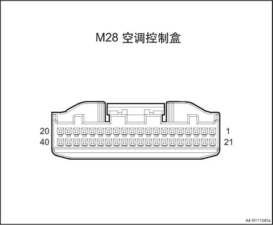
|
Connector No. |
Connector pin |
Wire Color |
Wire Diameter |
Pin Definition |
|
M28 |
1 |
Bl/G |
0.5 |
Key at ON position. |
|
M28 |
2 |
Bl/G |
0.5 |
Key at ON position. |
|
M28 |
7 |
Br/O |
0.5 |
Blower on signal |
|
M28 |
8 |
G/W |
0.5 |
Compressor request signal |
|
M28 |
10 |
B |
0.5 |
GND |
|
M28 |
13 |
B/Bl |
0.5 |
Temperature motor + (towards refrigeration) |
|
M28 |
14 |
P/W |
0.5 |
Temperature motor - (towards refrigeration) |
|
M28 |
15 |
P |
0.5 |
Mode motor + (face mode) |
|
M28 |
16 |
R/G |
0.5 |
Mode motor - (face mode) |
|
M28 |
17 |
O/W |
0.5 |
New air return motor + (towards new air) |
|
M28 |
18 |
R/B |
0.5 |
New air return motor - (towards new air) |
|
M28 |
20 |
Gr/W |
0.35 |
Sensor GND |
|
M28 |
21 |
Lg |
0.5 |
Battery + |
|
M28 |
23 |
R/W |
0.5 |
Inner cab temperature sensor - |
|
M28 |
24 |
Br/B |
0.35 |
Blower relay control |
|
M28 |
26 |
V |
0.5 |
Blower voltage negative feedback |
|
M28 |
27 |
O/V |
0.5 |
Blower voltage control |
|
M28 |
28 |
O |
0.5 |
BCAN_H |
|
M28 |
29 |
Y |
0.5 |
BCAN_L |
|
M28 |
30 |
B |
0.5 |
GND |
|
M28 |
33 |
Br |
0.35 |
Reference voltage (5V) |
|
M28 |
34 |
Br/Bl |
0.35 |
Temperature throttle position feedback |
|
M28 |
35 |
Br/B |
0.35 |
Mode throttle position feedback |
|
M28 |
36 |
Gr/Bl |
0.35 |
New air return throttle position feedback |
|
M28 |
37 |
Gr/B |
0.35 |
Evaporator temperature sensor signal |
|
M28 |
38 |
Gr |
0.35 |
Outer cab temperature sensor |
|
M28 |
39 |
Lg/Bl |
0.35 |
Inner cab temperature signal |
1. Open the engine cover
2. Disconnect the battery negative cable.
3. Recycle refrigerant
4. Dismantle the drive belt
5. Disassemble the compressor assembly.
1) Disconnect the compressor assembly wire harness connector 1.
2) Remove the 2 bolts ② fixing the air conditioner compressor inlet & exhaust pipe.
![]() 3) Remove the 3 fixing bolts ③ of
the compressor assembly.
3) Remove the 3 fixing bolts ③ of
the compressor assembly.
4) Take down the compressor assembly.
1 Install the compressor assembly.
1) Put the compressor assembly at the installation position
2) Install the 3 bolts ③ that fix the compressor assembly.
3) Mount and tighten the 2 bolts ② fixing the air conditioner compressor inlet & exhaust pipe.
4) Connect the compressor assembly wire harness connector 1.
![]() 2. Install the drive belt
2. Install the drive belt
3. Adding refrigerant
4. Connect the battery negative cable.
5. Close the engine compartment cover
1. Open the engine cover
2. Disconnect the battery negative cable.
3. Recycle refrigerant
4. Remove front bumper assembly. See the “front bumper assembly”.
5. Remove the radiator assembly. See the “radiator assembly”.
6. Disassemble the condenser
![]() 1) Remove the 4 bolts of condenser.
1) Remove the 4 bolts of condenser.
2) Take off the condenser
Install the condenser
![]() 1) Put the condenser at installation
position.
1) Put the condenser at installation
position.
2) Install and tighten the 4 fixing bolts of condenser.
2 Install the radiator assembly.
3. Install front bumper assembly
Add the refrigerant
Connect the battery negative cable.
6. Close engine compartment cover
1. Open the engine cover
2. Disconnect the battery negative cable.
3. Recycle refrigerant
4. Dismantle the pipeline and expansion valve assembly.
![]() 1) Disconnect compressor pressure
switch wire harness connector.
1) Disconnect compressor pressure
switch wire harness connector.
![]() 2) Remove the fixing bolts
connecting the air conditioning pipeline and the vehicle body.
2) Remove the fixing bolts
connecting the air conditioning pipeline and the vehicle body.
3) Remove the fixing bolts connecting the air conditioning pipeline and longitudinal beam.
![]()
![]() 4) Remove the 2 bolts of the
expansion valve.
4) Remove the 2 bolts of the
expansion valve.
5) Remove one fixing bolt from the air conditioning pipeline and compressor assembly, and disconnect the pipeline.
![]()
6) Remove one fixing bolt between the air conditioning pipeline and condenser, and disconnect the pipeline
![]() 7) Take down the pipeline and
expansion valve assembly
7) Take down the pipeline and
expansion valve assembly
1. Install the pipeline & expansion valve assy.
1) Put the pipeline & expansion valve assembly at installation position.
2) Connect the air conditioning pipeline and the compressor assembly, and tighten the bolts.
![]()
3) Connect the air conditioning pipeline and condenser, and tighten the bolts.
![]()
![]() 4) Install and tighten the 2 fixing
bolts of expansion valve.
4) Install and tighten the 2 fixing
bolts of expansion valve.
![]() 5) Install and tighten the fixing
bolts connecting the air conditioning pipeline and longitudinal beam.
5) Install and tighten the fixing
bolts connecting the air conditioning pipeline and longitudinal beam.
6) Install and tighten the fixing bolts connecting the air conditioning pipeline and the vehicle body.
![]()
![]() 7) Connect the air conditioning
pressure switch harness connector.
7) Connect the air conditioning
pressure switch harness connector.
2. Adding refrigerant
3. Connect the battery negative cable.
4. Close the engine compartment cover.
1. Open the engine cover
2. Disconnect the battery negative cable.
3. Discharge coolant.
4. Remove the blower water pipe assembly.
1) Loosen the clamp 1 and disconnect the blower water pipe from the front air conditioner host.
2) Loosen the clamp 2 and disconnect the connection between the blower water outlet pipe and the expansion kettle water return pipe.
![]()
3) Remove the connection between the blower water inlet pipe and the engine
![]()
1. Install blower water pipe assembly.
![]() 1) Connect the lower water pipe to
the engine, and fix with clamps.
1) Connect the lower water pipe to
the engine, and fix with clamps.
2) Connect the blower water pipe and the expansion kettle return pipe, fastening clamps.
3) Connect the blower water pipe and the front A/C host, and fix with clamps.
![]() 2. Adding coolant
2. Adding coolant
3. Connect the battery negative cable.
4. Close the engine compartment cover.
1. Open the engine cover
2. Disconnect the battery negative cable.
3. Recycle refrigerant
4. Remove the exhaust pipe assembly
![]() 1) Remove the exhaust pipe fixing
bolt, and disconnect the exhaust pipe and the compressor.
1) Remove the exhaust pipe fixing
bolt, and disconnect the exhaust pipe and the compressor.
![]() 2) Remove the exhaust pipe fixing
bolt, and disconnect the exhaust pipe and the condenser.
2) Remove the exhaust pipe fixing
bolt, and disconnect the exhaust pipe and the condenser.
1. Install the exhaust pipe assembly
![]() 1) Connector the exhaust pipe and
the condenser, install and tighten the 1 fixing bolts.
1) Connector the exhaust pipe and
the condenser, install and tighten the 1 fixing bolts.
![]() 2) Connector the exhaust pipe and
the compressor, install and tighten the 1 fixing bolts.
2) Connector the exhaust pipe and
the compressor, install and tighten the 1 fixing bolts.
2. Adding refrigerant
3. Connect the battery negative cable.
4. Close the engine compartment cover.
1. Open the engine cover
2. Disconnect the battery negative cable.
3. Dismantle the left front extension panel, refer to the “left front extension panel assembly”.
4. Dismantle the right front extension panel, refer to the “right front extension panel assembly”.
Remove sub-dash panel cover assembly See sub-dash panel cover assembly
6. Remove standby antenna, refer to the “standby antenna”.
7. Remove sub-dash panel upper trim assembly, refer to the “sub-dash panel upper trim assembly”.
8. Dismantle the front storage box, refer to “front storage box assembly”.
9. Dismantle the sub instrument panel house refer to sub instrument panel
10. Remove the steering wheel assembly, refer to the “Steering Wheel Assembly".
11. Disassemble the clock spring.Refer to “Clock Spring”.
12. Dismantle the combination switch assembly, refer to “combination switch assembly”
13. Remove the instrument cluster cover assembly, refer to the “instrument cluster cover assembly”.
14. Disassemble the steering column housing lower shell, refer to “steering column lower shell”.
15. Disassemble the instrument cluster assembly, refer to the “instrument cluster assembly”.
16. Dismantle the dashboard left end cover assembly, refer to the “dashboard left end cover assembly”.
17. Dismantle the dashboard right end cover assembly, refer to the “dashboard right end cover assembly”.
18. Dismantle the fuse box cover, refer to the “fuse box cover”.
19. Remove the driver lower guard assembly, refer to “driver lower guard assembly”.
20. Remove dashboard left vent, refer to the “dashboard left vent”.
21. Remove the central left trim panel assembly. Refer to the “central left trim panel assembly”.
22. Dismantle the glove box assembly refer to glove box assembly
23. Remove the co-pilot side trim panel, refer to “co-pilot side trim panel”.
24. Remove dashboard right vent, refer to the “dashboard right vent”.
25. Dismantle the right and the left A pillar upper panel assembly, refer to the “A pillar upper panel assembly”.
26. Remove the right and the left A pillar lower panel assembly , refer to the “A pillar lower panel assembly”.
27. Dismantle the front display screen, refer the the “front display screen”.
28. Dismantle the front display screen host, refer to the “front display screen host”.
29. Dismantle the 12V on-board power, refer to the “12V on-board power”
30. Dismantle the multimedia interface assembly, refer to the “multimedia interface assembly”.
31. Dismantle the dashboard body assembly, refer to the “dashboard body assembly”
32. Remove the face mode air duct assembly.
![]() 1). Remove 6 fixing screws fixing
the face mode air duct assembly.
1). Remove 6 fixing screws fixing
the face mode air duct assembly.
2) Take down the face mode air duct assembly.
1. Install the face mode air duct assembly.
![]() 1) Move the face mode air duct
assembly at installation place.
1) Move the face mode air duct
assembly at installation place.
2) Mount and tighten the 6 screws that fix the face mode air duct assembly.
2. Install the dashboard body assembly.
3. Install the multimedia interface assembly
4. Install the 12V on-board power.
5. Install front screen display body
6. Install the front display screen
7. Install the right and the left A column lower panel assembly
8. Install the right and the left A column upper panel assembly
9. Install the dashboard right vent.
10. Install the co-pilot side trim panel
11. Install the glove box assembly
12. Assemble the central left trim panel assembly
13. Install the dashboard left vent.
14. Install the driver lower guard assembly.
15. Install fuse box cover
16. Install the dashboard right end cover assembly
17. Install the dashboard left end cover assembly
18. Install the instrument cluster assembly.
19. Install the steering column housing lower upper shell
20. Install the instrument cluster cover assembly
21. Install the combination switch assembly
22. Assemble the clock spring
23. Install steering wheel assembly
24. Assemble the sub-dashboard body assembly.
25. Install the front storage box assembly
26) Install the sub-dash panel upper trim assembly
27. Install standby antenna
28. Install rear cover of sub-dash panel.
29. Install the right front extension panel assembly
30. Install the left front extension panel assembly
31). Connect the battery negative cable.
32. Close the engine compartment cover
1. Open the engine cover
2. Disconnect the battery negative cable.
3. Dismantle the left front extension panel, refer to the “left front extension panel assembly”.
4. Dismantle the right front extension panel, refer to the “right front extension panel assembly”.
Remove sub-dash panel cover assembly See sub-dash panel cover assembly
6. Remove standby antenna, refer to the “standby antenna”.
7. Remove sub-dash panel upper trim assembly, refer to the “sub-dash panel upper trim assembly”.
8. Dismantle the front storage box, refer to “front storage box assembly”.
9. Dismantle the sub instrument panel house refer to sub instrument panel
10. Remove the steering wheel assembly, refer to the “Steering Wheel Assembly".
11. Disassemble the clock spring.Refer to “Clock Spring”.
12. Dismantle the combination switch assembly, refer to “combination switch assembly”
13. Remove the instrument cluster cover assembly, refer to the “instrument cluster cover assembly”.
14. Disassemble the steering column housing lower shell, refer to “steering column lower shell”.
15. Disassemble the instrument cluster assembly, refer to the “instrument cluster assembly”.
16. Dismantle the dashboard left end cover assembly, refer to the “dashboard left end cover assembly”.
17. Dismantle the dashboard right end cover assembly, refer to the “dashboard right end cover assembly”.
18. Dismantle the fuse box cover, refer to the “fuse box cover”.
19. Remove the driver lower guard assembly, refer to “driver lower guard assembly”.
20. Remove dashboard left vent, refer to the “dashboard left vent”.
21. Remove the central left trim panel assembly. Refer to the “central left trim panel assembly”.
22. Dismantle the glove box assembly refer to glove box assembly
23. Remove the co-pilot side trim panel, refer to “co-pilot side trim panel”.
24. Remove dashboard right vent, refer to the “dashboard right vent”.
25. Dismantle the right and the left A pillar upper panel assembly, refer to the “A pillar upper panel assembly”.
26. Remove the right and the left A pillar lower panel assembly , refer to the “A pillar lower panel assembly”.
27. Dismantle the front display screen, refer the the “front display screen”.
28. Dismantle the front display screen host, refer to the “front display screen host”.
29. Dismantle the 12V on-board power, refer to the “12V on-board power”
30. Dismantle the multimedia interface assembly, refer to the “multimedia interface assembly”.
31. Dismantle the dashboard body assembly, refer to the “dashboard body assembly”
32. Remove the defroster air duct assy.
![]() 1). Remove 14 fixing screws fixing
the defroster air duct assembly.
1). Remove 14 fixing screws fixing
the defroster air duct assembly.
2) Take down the defrost air duct assembly.
1. Install the defroster air duct assembly.
![]() 1) Move the defroster air duct
assembly at installation place.
1) Move the defroster air duct
assembly at installation place.
2) Mount and tighten the 14 screws that fix the defroster air duct assembly.
2. Install the dashboard body assembly.
3. Install the multimedia interface assembly
4. Install the 12V on-board power.
5. Install front screen display body
6. Install the front display screen
7. Install the right and the left A column lower panel assembly
8. Install the right and the left A column upper panel assembly
9. Install the dashboard right vent.
10. Install the co-pilot side trim panel
11. Install the glove box assembly
12. Assemble the central left trim panel assembly
13. Install the dashboard left vent.
14. Install the driver lower guard assembly.
15. Install fuse box cover
16. Install the dashboard right end cover assembly
17. Install the dashboard left end cover assembly
18. Install the instrument cluster assembly.
19. Install the steering column housing lower upper shell
20. Install the instrument cluster cover assembly
21. Install the combination switch assembly
22. Assemble the clock spring
23. Install steering wheel assembly
24. Assemble the sub-dashboard body assembly.
25. Install the front storage box assembly
26) Install the sub-dash panel upper trim assembly
27. Install standby antenna
28. Install rear cover of sub-dash panel.
29. Install the right front extension panel assembly
30. Install the left front extension panel assembly
31). Connect the battery negative cable.
32. Close the engine compartment cover
1. Open the engine cover
2. Disconnect the battery negative cable.
3. Dismantle the left front extension panel, refer to the “left front extension panel assembly”.
4. Dismantle the right front extension panel, refer to the “right front extension panel assembly”.
Remove sub-dash panel cover assembly See sub-dash panel cover assembly
6. Remove standby antenna, refer to the “standby antenna”.
7. Remove sub-dash panel upper trim assembly, refer to the “sub-dash panel upper trim assembly”.
8. Dismantle the front storage box, refer to “front storage box assembly”.
9. Dismantle the sub instrument panel house refer to sub instrument panel
10. Remove the steering wheel assembly, refer to the “Steering Wheel Assembly".
11. Disassemble the clock spring.Refer to “Clock Spring”.
12. Dismantle the combination switch assembly, refer to “combination switch assembly”
13. Remove the instrument cluster cover assembly, refer to the “instrument cluster cover assembly”.
14. Disassemble the steering column housing lower shell, refer to “steering column lower shell”.
15. Disassemble the instrument cluster assembly, refer to the “instrument cluster assembly”.
16. Dismantle the dashboard left end cover assembly, refer to the “dashboard left end cover assembly”.
17. Dismantle the dashboard right end cover assembly, refer to the “dashboard right end cover assembly”.
18. Dismantle the fuse box cover, refer to the “fuse box cover”.
19. Remove the driver lower guard assembly, refer to “driver lower guard assembly”.
20. Remove dashboard left vent, refer to the “dashboard left vent”.
21. Remove the central left trim panel assembly. Refer to the “central left trim panel assembly”.
22. Dismantle the glove box assembly refer to glove box assembly
23. Remove the co-pilot side trim panel, refer to “co-pilot side trim panel”.
24. Remove dashboard right vent, refer to the “dashboard right vent”.
25. Dismantle the right and the left A pillar upper panel assembly, refer to the “A pillar upper panel assembly”.
26. Remove the right and the left A pillar lower panel assembly , refer to the “A pillar lower panel assembly”.
27. Dismantle the front display screen, refer the the “front display screen”.
28. Dismantle the front display screen host, refer to the “front display screen host”.
29. Dismantle the 12V on-board power, refer to the “12V on-board power”
30. Dismantle the multimedia interface assembly, refer to the “multimedia interface assembly”.
31. Dismantle the dashboard body assembly, refer to the “dashboard body assembly”
32. Dismantle the carpet assembly. Refer to the “carpet assembly”.
33. Remove the rear row feet mode air duct.
1). Remove 1 screw fixing the front part of the rear row feet mode air duct, and disconnect the air duct.
![]()
![]() 2) Remove the 4 nuts fixing the
rear part of the rear row feet mode air duct.
2) Remove the 4 nuts fixing the
rear part of the rear row feet mode air duct.
3) Take off the rear row feet mode air duct
1. Install the rear row feet mode air duct
1) Move the rear row feet mode air duct at installation place.
2) install the 4 nuts fixing the rear part of the rear row feet mode air duct.
![]()
3) install the one screw fixing the front part of the rear row feet mode air duct.
![]() 2. Assemble carpet assembly
2. Assemble carpet assembly
3. Install the dashboard body assembly.
4. Install the multimedia interface assembly
5. Install the 12V on-board power.
6. Install front screen display body
7. Install the front display screen
8. Install the right and the left A column lower panel assembly
9. Install the right and the left A column upper panel assembly
10. Install the dashboard right vent.
11. Install the co-pilot side trim panel
12. Install the glove box assembly
13. Assemble the central left trim panel assembly
14. Install the dashboard left vent.
15. Install the driver lower guard assembly.
16. Install fuse box cover
17. Install the dashboard right end cover assembly
18. Install the dashboard left end cover assembly
19. Install the instrument cluster assembly.
20. Install the steering column housing lower upper shell
21. Install the instrument cluster cover assembly
22. Install the combination switch assembly
23. Assemble the clock spring
24. Install steering wheel assembly
25. Assemble the sub-dashboard body assembly.
26. Install the front storage box assembly
27. Install the sub-dash panel upper trim assembly
28. Install standby antenna
29. Install rear cover of sub-dash panel.
30. Install the right front extension panel assembly
31. Install the left front extension panel assembly
32). Connect the battery negative cable.
33. Close the engine compartment cover
1. Open the engine cover
2. Disconnect the battery negative cable.
3. Dismantle the left front extension panel, refer to the “left front extension panel assembly”.
4. Dismantle the right front extension panel, refer to the “right front extension panel assembly”.
Remove sub-dash panel cover assembly See sub-dash panel cover assembly
6. Remove standby antenna, refer to the “standby antenna”.
7. Remove sub-dash panel upper trim assembly, refer to the “sub-dash panel upper trim assembly”.
8. Dismantle the front storage box, refer to “front storage box assembly”.
9. Dismantle the sub instrument panel house refer to sub instrument panel
10. Remove the steering wheel assembly, refer to the “Steering Wheel Assembly".
11. Disassemble the clock spring.Refer to “Clock Spring”.
12. Dismantle the combination switch assembly, refer to “combination switch assembly”
13. Remove the instrument cluster cover assembly, refer to the “instrument cluster cover assembly”.
14. Disassemble the steering column housing lower shell, refer to “steering column lower shell”.
15. Disassemble the instrument cluster assembly, refer to the “instrument cluster assembly”.
16. Dismantle the dashboard left end cover assembly, refer to the “dashboard left end cover assembly”.
17. Dismantle the dashboard right end cover assembly, refer to the “dashboard right end cover assembly”.
18. Dismantle the fuse box cover, refer to the “fuse box cover”.
19. Remove the driver lower guard assembly, refer to “driver lower guard assembly”.
20. Remove dashboard left vent, refer to the “dashboard left vent”.
21. Remove the central left trim panel assembly. Refer to the “central left trim panel assembly”.
22. Dismantle the glove box assembly refer to glove box assembly
23. Remove the co-pilot side trim panel, refer to “co-pilot side trim panel”.
24. Remove dashboard right vent, refer to the “dashboard right vent”.
25. Dismantle the right and the left A pillar upper panel assembly, refer to the “A pillar upper panel assembly”.
26. Remove the right and the left A pillar lower panel assembly , refer to the “A pillar lower panel assembly”.
27. Dismantle the front display screen, refer the the “front display screen”.
28. Dismantle the front display screen host, refer to the “front display screen host”.
29. Dismantle the 12V on-board power, refer to the “12V on-board power”
30. Dismantle the multimedia interface assembly, refer to the “multimedia interface assembly”.
31. Dismantle the dashboard body assembly, refer to the “dashboard body assembly”
32. Remove the rear row face mode air duct assembly.
![]() 1) Remove 1 fixing screws fixing
the front part of the rear row face mode air duct assembly.
1) Remove 1 fixing screws fixing
the front part of the rear row face mode air duct assembly.
2) Disconnect the front part of the rear row face mode air duct assembly.
3) Take down the front part of the rear row face mode air duct assembly.
![]()
4) Remove 2 fixing screws fixing the rear part of the rear row face mode air duct assembly.
5) Take down the rear part of the rear row face mode air duct assembly.
![]()
1 Install the rear row face mode air duct assembly.
1) Move the rear part of the rear row face mode air duct assembly at installation place.
2) Install the 2 fixing screws fixing the rear part of the rear row face mode air duct assembly.
![]()
![]() 3) Move the front part of the rear
row face mode air duct assembly at installation place.
3) Move the front part of the rear
row face mode air duct assembly at installation place.
4) Install 1 fixing screws fixing the front part of the rear row face mode air duct assembly.
![]() 2. Install the dashboard body assembly.
2. Install the dashboard body assembly.
3. Install the multimedia interface assembly
4. Install the 12V on-board power.
5. Install front screen display body
6. Install the front display screen
7. Install the right and the left A column lower panel assembly
8. Install the right and the left A column upper panel assembly
9. Install the dashboard right vent.
10. Install the co-pilot side trim panel
11. Install the glove box assembly
12. Assemble the central left trim panel assembly
13. Install the dashboard left vent.
14. Install the driver lower guard assembly.
15. Install fuse box cover
16. Install the dashboard right end cover assembly
17. Install the dashboard left end cover assembly
18. Install the instrument cluster assembly.
19. Install the steering column housing lower upper shell
20. Install the instrument cluster cover assembly
21. Install the combination switch assembly
22. Assemble the clock spring
23. Install steering wheel assembly
24. Assemble the sub-dashboard body assembly.
25. Install the front storage box assembly
26) Install the sub-dash panel upper trim assembly
27. Install standby antenna
28. Install rear cover of sub-dash panel.
29. Install the right front extension panel assembly
30. Install the left front extension panel assembly
31). Connect the battery negative cable.
32. Close the engine compartment cover
1. Open the engine cover
2. Disconnect the battery negative cable.
3. Dismantle the glove box assembly refer to glove box assembly
4. Dismantle the A/C control box assembly (electric)
1. Disconnect the A/C control box assembly (electric) wire harness connector ①.
2) Remove the 1 screw② fixing the air conditioner control box assembly.
![]() 3) Take down the A/C control box.
(electric)
3) Take down the A/C control box.
(electric)
1. Install the A/C control box assy. (electric)
1) Put the A/C control box assy. (Electric) at installation place.
2) Mount and tighten the 1 screw② fixing the air conditioner control box assembly.
3) Connect the A/C control box assembly (electric) wire harness connector ①.
![]() 2. Install glove box assembly
2. Install glove box assembly
3. Connect the battery negative cable.
4. Close the engine compartment cover.
1 Open the engine compartment cover.
2. Disconnect the battery negative cable.
3. Dismantle the blower.
![]() 1) Disconnect the blower harness
connector ①.
1) Disconnect the blower harness
connector ①.
2) Remove the 1 screw② fixing the blower.
3) Turn the blower clockwise to take it down.
1. Install blower.
![]() 1) Put the blower at installation
position
1) Put the blower at installation
position
2) Mount and tighten the 1 screw② fixing the blower.
3) Connect the blower harness connector ①.
2). Connect the battery negative cable.
3. Close the engine compartment cover
1. Dismantle the glove box assembly refer to glove box assembly
2. Disassemble the air filter.
![]() 1) Disassemble air filter cover
1) Disassemble air filter cover
2) Take out the air filter
1. Install the air filter.
![]() 1) Put the air filter at
installation position.
1) Put the air filter at
installation position.
2) Install the air filter cover and fit it tightly.
△Attention: Long-term non-replacement of filter will cause foreign matter to block air conditioner filter and increase blower noise increase and reduce air volume, etc.
Replacement period is 5000km-12000km,it is necessary to check and replace filter frequently during areas with serious air pollution or poor roads.
2. Install glove box assembly
1. Open the engine cover
2. Disconnect the battery negative cable.
3. Dismantle the left front extension panel, refer to the “left front extension panel assembly”.
4. Dismantle the right front extension panel, refer to the “right front extension panel assembly”.
Remove sub-dash panel cover assembly See sub-dash panel cover assembly
6. Remove standby antenna, refer to the “standby antenna”.
7. Remove sub-dash panel upper trim assembly, refer to the “sub-dash panel upper trim assembly”.
8. Dismantle the front storage box, refer to “front storage box assembly”.
9. Dismantle the sub instrument panel house refer to sub instrument panel
10. Remove the steering wheel assembly, refer to the “Steering Wheel Assembly".
11. Disassemble the clock spring.Refer to “Clock Spring”.
12. Dismantle the combination switch assembly, refer to “combination switch assembly”
13. Remove the instrument cluster cover assembly, refer to the “instrument cluster cover assembly”.
14. Disassemble the steering column housing lower shell, refer to “steering column lower shell”.
15. Disassemble the instrument cluster assembly, refer to the “instrument cluster assembly”.
16. Dismantle the dashboard left end cover assembly, refer to the “dashboard left end cover assembly”.
17. Dismantle the dashboard right end cover assembly, refer to the “dashboard right end cover assembly”.
18. Dismantle the fuse box cover, refer to the “fuse box cover”.
19. Remove the driver lower guard assembly, refer to “driver lower guard assembly”.
20. Remove dashboard left vent, refer to the “dashboard left vent”.
21. Remove the central left trim panel assembly. Refer to the “central left trim panel assembly”.
22. Dismantle the glove box assembly refer to glove box assembly
23. Remove the co-pilot side trim panel, refer to “co-pilot side trim panel”.
24. Remove dashboard right vent, refer to the “dashboard right vent”.
25. Dismantle the right and the left A pillar upper panel assembly, refer to the “A pillar upper panel assembly”.
26. Remove the right and the left A pillar lower panel assembly , refer to the “A pillar lower panel assembly”.
27. Dismantle the front display screen, refer the the “front display screen”.
28. Dismantle the front display screen host, refer to the “front display screen host”.
29. Dismantle the 12V on-board power, refer to the “12V on-board power”
30. Dismantle the multimedia interface assembly, refer to the “multimedia interface assembly”.
31. Dismantle the dashboard body assembly, refer to the “dashboard body assembly”
32. Dismantle the temperature control motor.
![]() 1) Disconnect the temperature
control motor harness connector ①.
1) Disconnect the temperature
control motor harness connector ①.
2) Remove the 3 screws② fixing the temperature control motor.
3) Remove the temperature control motor
1. Install the temperature control motor
![]() 1) Put the temperature control
motor at the installation position
1) Put the temperature control
motor at the installation position
2) Install the 3 screws② fixing the temperature control motor.
3) Connect the temperature control motor harness connector 1.
2. Install the dashboard body assembly.
3. Install the multimedia interface assembly
4. Install the 12V on-board power.
5. Install front screen display body
6. Install the front display screen
7. Install the right and the left A column lower panel assembly
8. Install the right and the left A column upper panel assembly
9. Install the dashboard right vent.
10. Install the co-pilot side trim panel
11. Install the glove box assembly
12. Assemble the central left trim panel assembly
13. Install the dashboard left vent.
14. Install the driver lower guard assembly.
15. Install fuse box cover
16. Install the dashboard right end cover assembly
17. Install the dashboard left end cover assembly
18. Install the instrument cluster assembly.
19. Install the steering column housing lower upper shell
20. Install the instrument cluster cover assembly
21. Install the combination switch assembly
22. Assemble the clock spring
23. Install steering wheel assembly
24. Assemble the sub-dashboard body assembly.
25. Install the front storage box assembly
26) Install the sub-dash panel upper trim assembly
27. Install standby antenna
28. Install rear cover of sub-dash panel.
29. Install the right front extension panel assembly
30. Install the left front extension panel assembly
31). Connect the battery negative cable.
32. Close the engine compartment cover
1. Open the engine cover
2. Disconnect the battery negative cable.
3. Dismantle the left front extension panel, refer to the “left front extension panel assembly”.
4. Dismantle the right front extension panel, refer to the “right front extension panel assembly”.
Remove sub-dash panel cover assembly See sub-dash panel cover assembly
6. Remove standby antenna, refer to the “standby antenna”.
7. Remove sub-dash panel upper trim assembly, refer to the “sub-dash panel upper trim assembly”.
8. Dismantle the front storage box, refer to “front storage box assembly”.
9. Dismantle the sub instrument panel house refer to sub instrument panel
10. Remove the steering wheel assembly, refer to the “Steering Wheel Assembly".
11. Disassemble the clock spring.Refer to “Clock Spring”.
12. Dismantle the combination switch assembly, refer to “combination switch assembly”
13. Remove the instrument cluster cover assembly, refer to the “instrument cluster cover assembly”.
14. Disassemble the steering column housing lower shell, refer to “steering column lower shell”.
15. Disassemble the instrument cluster assembly, refer to the “instrument cluster assembly”.
16. Dismantle the dashboard left end cover assembly, refer to the “dashboard left end cover assembly”.
17. Dismantle the dashboard right end cover assembly, refer to the “dashboard right end cover assembly”.
18. Dismantle the fuse box cover, refer to the “fuse box cover”.
19. Remove the driver lower guard assembly, refer to “driver lower guard assembly”.
20. Remove dashboard left vent, refer to the “dashboard left vent”.
21. Remove the central left trim panel assembly. Refer to the “central left trim panel assembly”.
22. Dismantle the glove box assembly refer to glove box assembly
23. Remove the co-pilot side trim panel, refer to “co-pilot side trim panel”.
24. Remove dashboard right vent, refer to the “dashboard right vent”.
25. Dismantle the right and the left A pillar upper panel assembly, refer to the “A pillar upper panel assembly”.
26. Remove the right and the left A pillar lower panel assembly , refer to the “A pillar lower panel assembly”.
27. Dismantle the front display screen, refer the the “front display screen”.
28. Dismantle the front display screen host, refer to the “front display screen host”.
29. Dismantle the 12V on-board power, refer to the “12V on-board power”
30. Dismantle the multimedia interface assembly, refer to the “multimedia interface assembly”.
31. Dismantle the dashboard body assembly, refer to the “dashboard body assembly”
32. Disassemble the throttle motor
![]() 1) Disconnect the throttle motor
harness connector ①.
1) Disconnect the throttle motor
harness connector ①.
2) Remove the 3 screws② fixing the throttle motor
3) Remove the throttle motor.
1. Install the throttle motor
![]() 1) Put the throttle motor at the
installation position
1) Put the throttle motor at the
installation position
2) Mount and tighten the 3 screws② fixing the throttle motor
3) Connect the throttle motor harness connector ①.
2. Install the dashboard body assembly.
3. Install the multimedia interface assembly
4. Install the 12V on-board power.
5. Install front screen display body
6. Install the front display screen
7. Install the right and the left A column lower panel assembly
8. Install the right and the left A column upper panel assembly
9. Install the dashboard right vent.
10. Install the co-pilot side trim panel
11. Install the glove box assembly
12. Assemble the central left trim panel assembly
13. Install the dashboard left vent.
14. Install the driver lower guard assembly.
15. Install fuse box cover
16. Install the dashboard right end cover assembly
17. Install the dashboard left end cover assembly
18. Install the instrument cluster assembly.
19. Install the steering column housing lower upper shell
20. Install the instrument cluster cover assembly
21. Install the combination switch assembly
22. Assemble the clock spring
23. Install steering wheel assembly
24. Assemble the sub-dashboard body assembly.
25. Install the front storage box assembly
26) Install the sub-dash panel upper trim assembly
27. Install standby antenna
28. Install rear cover of sub-dash panel.
29. Install the right front extension panel assembly
30. Install the left front extension panel assembly
31). Connect the battery negative cable.
32. Close the engine compartment cover
1. Open the engine cover
2. Disconnect the battery negative cable.
3. Dismantle the left front extension panel, refer to the “left front extension panel assembly”.
4. Dismantle the right front extension panel, refer to the “right front extension panel assembly”.
Remove sub-dash panel cover assembly See sub-dash panel cover assembly
6. Remove standby antenna, refer to the “standby antenna”.
7. Remove sub-dash panel upper trim assembly, refer to the “sub-dash panel upper trim assembly”.
8. Dismantle the front storage box, refer to “front storage box assembly”.
9. Dismantle the sub instrument panel house refer to sub instrument panel
10. Remove the steering wheel assembly, refer to the “Steering Wheel Assembly".
11. Disassemble the clock spring.Refer to “Clock Spring”.
12. Dismantle the combination switch assembly, refer to “combination switch assembly”
13. Remove the instrument cluster cover assembly, refer to the “instrument cluster cover assembly”.
14. Disassemble the steering column housing lower shell, refer to “steering column lower shell”.
15. Disassemble the instrument cluster assembly, refer to the “instrument cluster assembly”.
16. Dismantle the dashboard left end cover assembly, refer to the “dashboard left end cover assembly”.
17. Dismantle the dashboard right end cover assembly, refer to the “dashboard right end cover assembly”.
18. Dismantle the fuse box cover, refer to the “fuse box cover”.
19. Remove the driver lower guard assembly, refer to “driver lower guard assembly”.
20. Remove dashboard left vent, refer to the “dashboard left vent”.
21. Remove the central left trim panel assembly. Refer to the “central left trim panel assembly”.
22. Dismantle the glove box assembly refer to glove box assembly
23. Remove the co-pilot side trim panel, refer to “co-pilot side trim panel”.
24. Remove dashboard right vent, refer to the “dashboard right vent”.
25. Dismantle the right and the left A pillar upper panel assembly, refer to the “A pillar upper panel assembly”.
26. Remove the right and the left A pillar lower panel assembly , refer to the “A pillar lower panel assembly”.
27. Dismantle the front display screen, refer the the “front display screen”.
28. Dismantle the front display screen host, refer to the “front display screen host”.
29. Dismantle the 12V on-board power, refer to the “12V on-board power”
30. Dismantle the multimedia interface assembly, refer to the “multimedia interface assembly”.
31. Dismantle the dashboard body assembly, refer to the “dashboard body assembly”
32. Disassemble the inner and outer circulation throttle motor.
![]() 1) Disconnect the inner and outer
circulation throttle motor wire harness connector①
1) Disconnect the inner and outer
circulation throttle motor wire harness connector①
2) Remove the 3 screws② fixing the inner and outer circulation throttle motor.
3) Take down the inner and outer circulation throttle motor.
1. Install the inner and outer circulation throttle motor.
![]() 1) Put the inner and outer
circulation throttle motor at installation place.
1) Put the inner and outer
circulation throttle motor at installation place.
2) Remove the 3 screws② fixing the inner and outer circulation throttle motor.
3) Connect the inner and outer circulation throttle motor wire harness connector ①.
2. Install the dashboard body assembly.
3. Install the multimedia interface assembly
4. Install the 12V on-board power.
5. Install front screen display body
6. Install the front display screen
7. Install the right and the left A column lower panel assembly
8. Install the right and the left A column upper panel assembly
9. Install the dashboard right vent.
10. Install the co-pilot side trim panel
11. Install the glove box assembly
12. Assemble the central left trim panel assembly
13. Install the dashboard left vent.
14. Install the driver lower guard assembly.
15. Install fuse box cover
16. Install the dashboard right end cover assembly
17. Install the dashboard left end cover assembly
18. Install the instrument cluster assembly.
19. Install the steering column housing lower upper shell
20. Install the instrument cluster cover assembly
21. Install the combination switch assembly
22. Assemble the clock spring
23. Install steering wheel assembly
24. Assemble the sub-dashboard body assembly.
25. Install the front storage box assembly
26) Install the sub-dash panel upper trim assembly
27. Install standby antenna
28. Install rear cover of sub-dash panel.
29. Install the right front extension panel assembly
30. Install the left front extension panel assembly
31). Connect the battery negative cable.
32. Close the engine compartment cover
1. Open the engine cover
2. Disconnect the battery negative cable.
3. Recycle refrigerant
4. Discharge coolant.
5. Dismantle the left front extension panel, refer to the “left front extension panel assembly”.
6. Dismantle the right front extension panel, refer to the “right front extension panel assembly”.
7. Remove sub-dash panel cover assembly, refer to the “sub-dash panel cover assembly”.
8. Remove standby antenna, refer to the “standby antenna”.
9. Remove sub-dash panel upper trim assembly, refer to the “sub-dash panel upper trim assembly”.
10. Dismantle the front storage box, refer to “front storage box assembly”.
11. Dismantle the sub instrument panel house refer to sub instrument panel
12. Remove the steering wheel assembly, refer to the “Steering Wheel Assembly".
13. Disassemble the clock spring.Refer to “Clock Spring”.
14. Dismantle the combination switch assembly, refer to “combination switch assembly”
15. Remove the instrument cluster cover assembly, refer to the “instrument cluster cover assembly”.
16. Disassemble the steering column housing lower shell, refer to “steering column lower shell”.
17. Disassemble the instrument cluster assembly, refer to the “instrument cluster assembly”.
18. Dismantle the dashboard left end cover assembly, refer to the “dashboard left end cover assembly”.
19. Dismantle the dashboard right end cover assembly, refer to the “dashboard right end cover assembly”.
20. Dismantle the fuse box cover, refer to the “fuse box cover”.
21. Remove the driver lower guard assembly, refer to “driver lower guard assembly”.
22. Remove dashboard left vent, refer to the “dashboard left vent”.
23. Remove the central left trim panel assembly. Refer to the “central left trim panel assembly”.
24. Dismantle the glove box assembly refer to glove box assembly
25. Remove the passenger side panel Assembly. Refer to the passenger side panel Assembly
26. Remove dashboard right vent, refer to the “dashboard right vent”.
27. Dismantle the right and the left A pillar upper panel assembly, refer to the “A pillar upper panel assembly”.
28. Remove the right and the left A pillar lower panel assembly , refer to the “A pillar lower panel assembly”.
29. Dismantle the front display screen, refer the the “front display screen”.
30. Dismantle the front display screen host, refer to the “front display screen host”.
31. Dismantle the 12V on-board power, refer to the “12V on-board power”
32. Dismantle the multimedia interface assembly, refer to the “multimedia interface assembly”.
33. Dismantle the dashboard body assembly, refer to the “dashboard body assembly”
34. Disassemble the front anti-collision beam assembly, refer to the”front anti-collision beam assembly”.
35. Remove the rear row face mode air duct assembly. See the”rear row face mode air duct assembly”.
36. Remove the rear row feet mode air duct. See the “rear row feet mode air duct”.
37. Disassemble the inner and outer circulation throttle motor. See the “inner and outer circulation throttle motor”.
38. Dismantle the temperature control motor. See the “temperature control motor”.
39. Disassemble the throttle motor. See the “throttle motor”.
40. Dismantle the A/C control box assembly (electric). See the” A/C control box assembly (electric)” .
41. Dismantle the A/C host assembly.
1) Remove the front A/C pipeline expansion valve fixing bolt, disconnect the front A/C pipeline.
![]()
![]() 2) Remove the bolt, and take down
the evaporator core inlet/outlet sleeve assembly.
2) Remove the bolt, and take down
the evaporator core inlet/outlet sleeve assembly.
3) Remove the blower water pipe clamps, and disconnect the blower water pipe.
![]()
4) Remove the nuts, and take down the blower water pipe protective sleeves.
![]()
5) Disconnect the adjustable resistance and blower wire harness connectors.
![]()
![]() 6) Remove the 2 bolts fixing the
A/C host assembly.
6) Remove the 2 bolts fixing the
A/C host assembly.
7. Dismantle the A/C host assembly.
1. Assemble the A/C host
1) Put the A/C host assembly at the installation position
![]() 1) Install the 2 bolts that fix the
A/C host assembly.
1) Install the 2 bolts that fix the
A/C host assembly.
Tighten the moment of force to 5~7N·m.
![]() 2) Connect the adjustable
resistance and blower wire harness connectors.
2) Connect the adjustable
resistance and blower wire harness connectors.
3) Install the blower water pipe protective sleeve assembly, and tighten the 2 fixing bolts.
![]() Tightening torque 7 ~ 9N·m
Tightening torque 7 ~ 9N·m
![]() 4) Connect the blower water pipe,
and tighten the blower water pipe with clamps.
4) Connect the blower water pipe,
and tighten the blower water pipe with clamps.
5) Install the evaporator core inlet/outlet sleeve assembly, and tighten the 2 fixing bolts.
![]() Tightening torque 7 ~ 9N·m
Tightening torque 7 ~ 9N·m
6) Connect the expansion valve and the A/C host, and tighten the 2 fixing bolts.
![]() Tightening torque 7 ~ 9N·m
Tightening torque 7 ~ 9N·m
2. Install the A/C control box assy. (electric)
3. Install the throttle motor
4. Install the temperature control motor
5. Install the inner and outer circulation throttle motor.
6. Install the rear row feet mode air duct
7 Install the rear row face mode air duct assembly.
8. Install the front anti-collision beam assembly
9. Install the dashboard body assembly.
10. Install the multimedia interface assembly
11. Install the 12V on-board power.
12. Install front screen display body
13. Install the front display screen
14. Install the right and the left A column lower panel assembly
15. Install the right and the left A column upper panel assembly
16. Install the dashboard right vent.
17. Install the co-pilot side trim panel
18. Install the glove box assembly
19. Assemble the central left trim panel assembly
20. Install the dashboard left vent.
21. Install the driver lower guard assembly.
22. Install fuse box cover
23. Install the dashboard right end cover assembly
24. Install the dashboard left end cover assembly
25. Install the instrument cluster assembly.
26. Install the steering column housing lower upper shell
27. Install the instrument cluster cover assembly
28. Install the combination switch assembly
29. Assemble the clock spring
30. Install steering wheel assembly
31. Assemble the sub-dashboard body assembly.
32. Install the front storage box assembly
33. Install the sub-dash panel upper trim assembly
34. Install standby antenna
35. Install rear cover of sub-dash panel.
36. Install the right front extension panel assembly
37. Install the left front extension panel assembly
38. Adding coolant
39. Adding refrigerant
40. Connect the battery negative cable.
41. Close the engine compartment cover
1. Open the engine cover
2. Disconnect the battery negative cable.
3. Recycle refrigerant
4. Discharge coolant.
5. Dismantle the left front extension panel, refer to the “left front extension panel assembly”.
6. Dismantle the right front extension panel, refer to the “right front extension panel assembly”.
7. Remove sub-dash panel cover assembly, refer to the “sub-dash panel cover assembly”.
8. Remove standby antenna, refer to the “standby antenna”.
9. Remove sub-dash panel upper trim assembly, refer to the “sub-dash panel upper trim assembly”.
10. Dismantle the front storage box, refer to “front storage box assembly”.
11. Dismantle the sub instrument panel house refer to sub instrument panel
12. Remove the steering wheel assembly, refer to the “Steering Wheel Assembly".
13. Disassemble the clock spring.Refer to “Clock Spring”.
14. Dismantle the combination switch assembly, refer to “combination switch assembly”
15. Remove the instrument cluster cover assembly, refer to the “instrument cluster cover assembly”.
16. Disassemble the steering column housing lower shell, refer to “steering column lower shell”.
17. Disassemble the instrument cluster assembly, refer to the “instrument cluster assembly”.
18. Dismantle the dashboard left end cover assembly, refer to the “dashboard left end cover assembly”.
19. Dismantle the dashboard right end cover assembly, refer to the “dashboard right end cover assembly”.
20. Dismantle the fuse box cover, refer to the “fuse box cover”.
21. Remove the driver lower guard assembly, refer to “driver lower guard assembly”.
22. Remove dashboard left vent, refer to the “dashboard left vent”.
23. Remove the central left trim panel assembly. Refer to the “central left trim panel assembly”.
24. Dismantle the glove box assembly refer to glove box assembly
25. Remove the passenger side panel Assembly. Refer to the passenger side panel Assembly
26. Remove dashboard right vent, refer to the “dashboard right vent”.
27. Dismantle the right and the left A pillar upper panel assembly, refer to the “A pillar upper panel assembly”.
28. Remove the right and the left A pillar lower panel assembly , refer to the “A pillar lower panel assembly”.
29. Dismantle the front display screen, refer the the “front display screen”.
30. Dismantle the front display screen host, refer to the “front display screen host”.
31. Dismantle the 12V on-board power, refer to the “12V on-board power”
32. Dismantle the multimedia interface assembly, refer to the “multimedia interface assembly”.
33. Dismantle the dashboard body assembly, refer to the “dashboard body assembly”
34. Disassemble the front anti-collision beam assembly, refer to the”front anti-collision beam assembly”.
35. Remove the rear row face mode air duct assembly. See the”rear row face mode air duct assembly”.
36. Remove the rear row feet mode air duct. See the “rear row feet mode air duct”.
37. Disassemble the inner and outer circulation throttle motor. See the “inner and outer circulation throttle motor”.
38. Dismantle the temperature control motor. See the “temperature control motor”.
39. Disassemble the throttle motor. See the “throttle motor”.
40. Dismantle the A/C control box assembly (electric). See the” A/C control box assembly (electric)” .
41. Disassemble the A/C host assembly. See the “A/C host assembly”.
42. Disassemble the evaporator core.
![]() 1) Dismantle the 3 screws and
remove the blower shell.
1) Dismantle the 3 screws and
remove the blower shell.
![]()
2) Remove the 4 screws fixing evaporator core, and take down the evaporator core.
![]()
1. Check if the part is damaged; if damaged, please replace it.
2. Install the evaporator core
1) Install the evaporator core into the front A/C housing, and tighten the 4 fixing screws.
![]()
2) Assemble the A/C host and blower shell, and tighten the 3 fixing screws.
![]()
![]() 3. Install the A/C host assembly
3. Install the A/C host assembly
4. Install the A/C control box assy. (electric)
5. Install the throttle motor
6. Install the temperature control motor
7. Install the inner and outer circulation throttle motor.
8. Install the rear row feet mode air duct
9 Install the rear row face mode air duct assembly.
10. Install the front anti-collision beam assembly
11. Install the dashboard body assembly.
12. Install the multimedia interface assembly
13. Install the 12V on-board power.
14. Install front screen display body
15. Install the front display screen
16. Install the right and the left A column lower panel assembly
17. Install the right and the left A column upper panel assembly
18. Install the dashboard right vent.
19. Install the co-pilot side trim panel
20. Install the glove box assembly
21. Assemble the central left trim panel assembly
22. Install the dashboard left vent.
23. Install the driver lower guard assembly.
24. Install fuse box cover
25. Install the dashboard right end cover assembly
26. Install the dashboard left end cover assembly
27. Install the instrument cluster assembly.
28. Install the steering column housing lower upper shell
29. Install the instrument cluster cover assembly
30. Install the combination switch assembly
31. Assemble the clock spring
32. Install steering wheel assembly
33. Assemble the sub-dashboard body assembly.
34. Install the front storage box assembly
35. Install the sub-dash panel upper trim assembly
36. Install standby antenna
37. Install rear cover of sub-dash panel.
38. Install the right front extension panel assembly
39. Install the left front extension panel assembly
40. Adding coolant
41. Adding refrigerant
42. Connect the battery negative cable.
43. Close the engine compartment cover
With the development of automotive electronic technology, the configuration functions of body electronic appliances in terms of safety and comfort are more and more abundant. In order to decrease the vehicle fault rate, and realize the more effective control, the vehicle uses BCM (body control module) to intensively control the operation of the each electric unit assembled on the vehicle. BCM contains a RF receiver.
The power tailgate control system is composed of the tailgate controller assembly, buzzer, kick sensor controller assembly, kick sensor antenna, etc
![]()
1. Body Control Module(BCM)
2. Wireless charging module
3. Electric Window Anti-pinch Controller
4. Kick sensor controller
5. Kick sensor antenna
6. Tailgate controller assembly
Functions of BCM: anti-theft alarm, central locking control, external light control, internal light control, wiper control, electric window control, rear defrost control, automatic closing of sunroof, power control of start stop load, etc., internal integrated gateway, PEPS and ESCL control. When the body controller and its sensors and actuators have different grounding, and there is a deviation of ± 1V from the ground level, it will not lead to functional failure.
1. BCM power management function:
The BCM power is KL30 constant power, and the system functions are executed according to the corresponding power supply&voltage management logic. The voltage range of BCM input signal acquisition is 7-18v, the normal working voltage range is 9-16v, the normal working voltage range of CAN network is 6.5-18v, and the normal working voltage range of LIN network is 7-18v.
The normal working voltage range of diagnosis function is 8-16V. If there is no special explanation, the error of time parameter is 10%.
|
Regional function |
Voltage state |
Description |
Execution strategy |
|
BCM output signal |
Overvoltage |
Higher than 16 Vfor more than 440ms, do not return to normal state. |
Stop output |
|
High voltage |
Higher than 16V for more than 40ms, return to normal state in 440ms. |
Allow output |
|
|
Normal |
Lower than 15.5V for more than 2000ms in overvoltage state, return to normal state; higher than 9V and lower than 16V; higher than 9.5V for more than 2000ms in undervoltage state, then return to normal state |
||
|
Low voltage |
Lower than 9V for more than 40ms, return to normal state in 80ms. |
||
|
Undervoltage |
Lower than 9V for more than 80ms, do not return to normal state. |
Stop output |
|
|
CAN network |
Overvoltage |
Higher than 18V for more than 440ms, do not return to normal state. |
Stop communication |
|
High voltage |
Higher than 18V for more than 40ms, return to normal state in 440ms. |
Allow communication |
|
|
Normal |
Lower than 17.5V for more than 2000ms in overvoltage state, return to normal state; higher than 6.5V and lower than 18V; higher than 7V for more than 2000ms in undervoltage state, then return to normal state |
||
|
Low voltage |
Lower than 6.5V for more than 1000ms, return to normal state in 1040ms. |
||
|
Undervoltage |
Lower than 6.5V for more than 1040ms, do not return to normal state. |
Stop communication |
|
|
LIN network |
Overvoltage |
Higher than 18V for more than 0ms, do not return to normal state. |
Stop communication |
|
High voltage |
Lower than 18V for more than 200ms in overvoltage state, return to normal state; higher than 7V and lower than 18V; higher than 7V for more than 200ms in undervoltage state, then return to normal state |
Allow communication |
|
|
Undervoltage |
Lower than 7V for more than 0ms, do not return to normal state. |
Stop communication |
|
|
Diagnosis function |
Overvoltage |
Higher than 16V for more than 0ms, do not return to normal state. |
Stop diagnosis |
|
Normal |
Lower than 16V for more than 200ms in overvoltage state, return to normal state; higher than 8V and lower than 16V; higher than 8V for more than 200ms in undervoltage state, then return to normal state |
Allow diagnosis |
|
|
Undervoltage |
Lower than 8V for more than 0ms, do not return to normal state. |
Stop diagnosis |
2. Collision Signal
There are two types of collision signal: hardwire signal and network signal
1) Hardwire signal: the hardwire signal is a PWM input with a cycle of 240ms. After the BCM is powered on, it needs to give the ACU module 500ms as the initial stable time. There are three collision signal modes:
(1) Signal mode 1: when there is no collision (normal mode): 200ms ± 10% high level, 40ms ± 10% low level.
(2) Signal mode 2: when collision occurs, reverse PWM signal is output: 200ms ± 10% low level, 40ms ± 10% high level, a total of 20 ± 10% effective high-level pulses, and then return to normal mode pulse.
△Attention: PWM collision reverse signal output of ACU is asynchronous trigger, that is, regardless of whether it is high or low before the collision, it will start to output a low level lasting for 200ms at the time of collision.
(3) Signal mode 3: the signal mode received by the BCM when the collision signal generator device is damaged due to collision, non mode 1 and non mode 2. 2) Network Signal
The collision signal on the network is sent by SRS node. In case of collision, CrashInfo = 0x1:Crash Occurred of 0x07d is sent, and when there is no collision, CrashInfo = 0x0:No Crash is sent.
3) Function Description
When the switch is in IG1, the BCM starts to judge the relevant signal 500 ms delay after power on. When the collision signal received by the BCM changes to signal mode 2 or the network signal received by the BCM is CrashInfo = 0x1:Crash Occurred, the BCM will judge that the vehicle has collided and enter the collision mode.
When the ignition switch passes through an ON-OFF-ON cycle, the hard wire collision signal received by the BCM returns to signal mode 1 or the hard wire collision signal received by the BCM changes to signal mode 3; and the network signal crashinfo received by the BCM changes to 0x0:No Crash, the BCM will exit the collision mode.
3. RKE Function
1) Low configuration BCM standard RKE function RKE configuration model has remote control function, which requires BCM and RKE key to complete mutual matching At present, the wireless frequency of RF communication is 433.92MHz ± 100kHz, and RKE key has three keys, including four door unlocking key, four door locking key and tail door unlocking key. The BCM and RKE keys are matched by diagnosis. During the matching process of BCM and RKE keys, the BCM tracks the matching process through the corresponding indicator prompt;
(1) When the diagnosis enters RKE key matching (waiting for the first key to learn), the right steering light is constant on.
(2) When the diagnosis enters RKE key matching (waiting for the second key to learn), the left and right steering lights are constant on.
(3) After the second key is matched, the left and right steering lights are off. Note:
(1) At the beginning of diagnosis matching RKE key, the BCM will erase all previously matched RKE keys.
(2) In the process of RKE key matching, the locking and unlocking buttons need to be pressed at the same time.
(3) At most two keys can be matched at one time.
(4) For the specific definition of RKE matching related diagnostic services, refer to the diagnostic questionnaire EDS.
2) Working temperature
|
Temperature |
Temperature range |
|
Lowest working temperature |
≤-40 ℃ |
|
Lowest storage temperature |
≤-40 ℃ |
|
Highest working temperature |
≤80 ℃ |
|
Highest storage temperature |
≤90 ℃ |
The turn signal is mainly composed of a left front turn signal, a left turn signal, a left rear turn signal, a left turn indicator, a right front turn signal, a right turn signal, a right rear turn signal, and a right turn indicator. Among them, the left three turn signals are combined into one output, and the three lights on the right are combined into one output.
1. Basic functions of turn signals:
When the ignition switch is on, the turn switch is in the left or right turn position. The left or right turn lamp will be on for 400 ms and off for 400 ms (75 ± 2 times / min). When the turn signal switch is on, the corresponding turn signal lamp output shall be at least 3 cycles; if the turn signals exceeds 3 cycles, the turn signal lamp shall be turned off immediately after the switch is disconnected
2. Lane change indicator function
When the ignition switch is on, the turn signal lamp on a certain side will flicker with the working cycle of 400ms on and 400ms off due to the turn signal switch on the same side
(75±2) min
3. Function of hazard warning lamp: under any ignition switch position, once the hazard warning lamp switch is pressed (jump from H to L), the two sides flash at the same time with a working cycle of 400ms on and 400ms off
/
4. Turn signal self diagnosis
If at least one (21W) turn signal lamp is damaged, other turn signal lamps on the same side will work at frequency doubling, that is, flashing at a frequency of about 150 ± 4 times / min. the working signal of the turn signal transmitted on ECAN is synchronized with the output signal, and the corresponding open circuit DTC is recorded. In the steering state function, if only one (5W) turn signal lamp is damaged, the DTC will not be recorded and frequency doubling will not be done.
The automatic lighting function allows the position lamp and low beam lamp to be turned on when the external light is very dark and the light control switch is in the automatic position. The external situation can be known through the light sensor. When the judging state changes from night to day, the operation of turning off the light is delayed for 7 S. if the judged state changes to night within the waiting time for closing, the closing delay timing is exited and the night operation is executed. The input of automatic light switch becomes invalid and the current timing is exited.
The interior light system is mainly divided into two parts: one is interior light control, the other is power saving control. Interior light control, mainly the activation and shutdown of cabin lights Power saving control, mainly to open or close the power saving control relay
1. Interior roof lamp
1) The interior roof lamp will be lit when either of the following conditions is met:
(1) The vehicle is unlocked from locked state. (2) Ignition switch is changed to OFF from ON. (3) Either door is open.
2) The interior roof lamp gradually goes out, the fade out time is 5 ± 0.5s, and the actual brightness adjustment speed changes by 1% in 50ms :
(1) The vehicle is unlocked from locked state, the interior roof lamp is lit for 15s before going out.
(2) When the ignition switch is at OFF or ACC, a door changes from closed to open, and the interior roof lamp lights up. When all doors are closed, the interior roof lamp works for 15s before gradually going out If a new door is opened, the time will be counted again for 15s, and the later triggered one can cover the previous time.
(3) When the ignition switch changes from ON to OFF, the interior roof lamp will work continuously for 15s, and then gradually goes out.
(4) When the collision signal is effective, the interior roof lamp will be on immediately, and after 15 minutes, it will gradually turn off. 3) Interior roof lamp immediately goes out
(1) When the door is open, the interior roof lamp continues to work. If the door opening time is greater than 15 minutes, the interior roof lamp is immediately extinguished.
(2) After a successful lock, the interior roof lamp will be turned off immediately. The lamp off after successful lock is prior to the lamp gradually going out after unlocking.
/
(3) When the four doors are closed, the ignition switch changes from OFF or ACC to ON, and the interior roof lamp is off immediately.
(4) when the ignition switch is ON, the interior roof lamp is lit when any door is open, it will goes out immediately when all doors are closed.
(5) After the collision triggered interior roof lamp, if the ignition switch changes from OFF to ON, the interior roof lamp immediately goes out. 2. Power saving function
1) When the ignition switch is at ACC, ON or START positions, the power saving function is always effective.
2) When the power saving relay meets any of the following conditions, the relay will open: (1) Any door status signal changes(including tail door) (2) RKE unlock signal
(3) Mechanical key unlocking signal.
(4) Central control unlock signal
(5) Ignition status signal.
(6) PEPS remote control, passive unlocking signal.
3) The power saving relay will be closed if any of the following conditions are met:
(1) After the power saving relay is connected, the signal of relay opening does not change, and then the power saving relay will be closed after 15 minutes. If no change is detected in the signal of the relay
after the relay is turned on again, the 15 minute time recording will be started again.
(2) BCM enters sleep mode, it will close power saving relay.
BCM controls the front wiper / washer system of the vehicle. The power supply of the wiper motor is constant power, which can ensure that the wiper can return to the home position after the ignition switch is changed to OFF.
1. Intermittent function of front wiper
When the ignition switch is ON, the BCM judges the intermittent time according to the gear position of the combined switch. When the vehicle speed is greater than 60km / h (60km / h is the default configuration and can be configured as 100km / h), the intermittent time of each gear will be reduced by 4s. The corresponding relationship between intermittent gear and time is shown in the table below
|
Gear position |
Typ (Ω) |
Wiper gear position sign |
Time(≤ 60 km/ h) |
Time (> 60 km / h) |
|
Pos1 |
0 |
- |
1s |
0s |
|
Pos2 |
110 |
- |
2s |
1s |
|
Pos3 |
240 |
- |
5s |
2s |
|
Pos4 |
510 |
- |
8s |
5s |
|
Pos5 |
1100 |
- |
13s |
8s |
2. Front wiper maintenance function
When the ignition switch is OFF for 30 seconds, the wiper is in the return zone. Turn the wiper to the inching position for more than 2 seconds, and the front wiper will automatically reach the maintenance position at low speed. When the wiper switch is turned to any gear (including the linkage of front water spray wiper), the wiper will exit the maintenance mode, and it will immediately execute the corresponding action of the current switch.
BCM includes the vehicle door lock system: central locking and unlocking, remote locking and unlocking, mechanical key unlocking and locking, and the vehicle performs automatic unlocking, automatic re-locking, tail door unlocking, anti-mislocking function and collision forced unlocking when the key is pulled out of the ignition lock,
1. RKE four doors locking
When the ignition switch is OFF, BCM receives an effective RKE locking signal, and the four doors, the hood and the tail door are all closed, then the BCM performs the four doors locking and performs the defend confirmation. If the driver's door is closed and other doors are not closed, BCM performs four doors locking, enters the pre-defense state, and executes the defense confirmation after all the doors are closed.
2. PEPS four doors locking
When the ignition switch is OF, and protection status is not triggered frequently, the driver side low frequency antenna receives the corresponding signal and BCM executes four doors unlocking and unlocking confirmation.
3. TBOX tail door open
When the vehicle is in the defense state, BCM receives the remote unlocking tail door signal from the TBOX. The effective signal does not unlock the defense. Within 30 seconds after receiving the effective signal, it will receive the effective tail door unlocking signal and executes the 500ms tail door opening. If the tail door is not opened within 30 seconds after receiving a valid signal, or the tail door is closed again after the tail door is opened, the defense state will be re entered, and the door can not be unlocked through the tail door unlocking signal.
4. Electric tail door start
1) Electric tail door kick-start
When the BCM is in the defense / pre-defense state, the BCM receives LIN1 bus signal and drives the tail door antenna to search a legal key. If there is a legal key in the tailgate area, the BCM will trigger a legal kick prompt, but the whole vehicle remains in the defensed state except the tail door. Meanwhile BCM sends 5 frames OrderInformation (0x2c1)= A:PLG request
To CAN bus
When the BCM receives the LIN1 bus signal in the unlocked state, the BCM drives the tail gate antenna to search for a legal key. If there is a legal key in the tailgate area, the BCM sends orderinformation (0x2c1) = A: PLG request to CAN bus.
When the BCM is sleeping, if KS is triggered, KS first wakes up itself and then wakes up the master node BCM by pulling down the LIN bus. At this time, the BCM will wake up locally and the CAN network will not wake up After the BCM wakes up locally, it sends KSEnable signal to KS via Lin, and KS will send KS_ Kickdetected signal to BCM. BCM receives KS_ Kickdetected (0x26) changes from 0 to 1, and then drives the antenna to find the key. If a legal key is found, BCM wakes up the CAN network and send OrderInformation to TGC If no legal key is found, it will enter into sleep according to the sleep strategy
5. RKE Open / pause / close power tail door function
After the user presses the remote control key for 1.5 seconds, the BCM sends the tail door opening command, and the PLG switches between the open / pause / close states according to the current state of the power tail door.
When BCM is in the defense / pre-defense state, the BCM receives an effective RKE tail door opening signal, and the BCM triggers an unlocking prompt, but the whole vehicle remains in the defense state except the tail door. Meanwhile BCM sends OrderInformation (0x2c1)= A:PLG request to CAN bus
6. PEPS Open / pause / close power tail door function
After the user presses the tail door PE switch, BCM searches whether there is a legal key in the tail door area. If so, BCM sends the tail door opening command, and the PLG switches between the open / pause / close three states according to the current state of the electric tailgate.
When BCM is in the defense / pre-defense state, BCM receives tail door unlock signal, it drives the tail door antenna to search a legal key. If there is a legal key in the tailgate area, the BCM will trigger a legal unlocking prompt, but the whole vehicle remains in the defensed state except the tail door. Meanwhile BCM sends 5 frames OrderInformation (0x2c1)= A:PLG request
To CAN bus 7. Finding car function
When the ignition switch is OFF, BCM receives the vehicle search signal from TBOX, the vehicle turn lamps flash at the frequency of 1Hz,
and the horn rings at the frequency of 1Hz after the turn lamps flash for three times When the BCM receives the Tbox vehicle searching signal again, it will immediately stop the output of the turn signal and horn. When the BCM receives the Tbox vehicle searching signal again, it will immediately stop the output of the turn signal and horn and executes certain unlocking or locking.
8. Collision unlocking function
When the ignition switch is IG1, BCM receives an effective collision signal, it drives the four door lock motor to unlock once every 400ms, continuously for three times, and shielding all locking functions at the same time. When the ignition switch goes through an ON-OFF-ON process, shielding lock function is removed.
PEPS system consists of the following components, including BCM (including peps), SSB switch, indoor LF antenna, driver door LF antenna, tail door LF antenna, ESCL and PEPS key.
1. PE frequent trigger protection: To avoid the power consumption caused by unauthorized frequent operations of the keyless entry button outside the vehicle, the frequent trigger protection function is designed. When some action triggers the protection,
it will not respond to the request of the trigger source for a period of time. If the interval between two times of triggered PKE unlocking or locking is less than 1 second (cooling time), the second trigger will be ignored. If the microswitch is pressed continuously for more than 3 times within 6 seconds, the protection time of 10 seconds will be triggered. During this period, pressing the microswitch is invalid
2. Passive Entry (PE)
Unlock function: when the door handle is pressed, the door handle antenna triggers the key to authenticate with the peps controller. If the authentication is successful, the intelligent key can enter the performance and the PEPS controller will send the unlock request to the body controller, the door is unlocked.
Lock function: after all doors are closed, when pressing the door handle button, search for the key on the side of the door handle, if there is no key, can not lock, if there is a key, do the key authentication and check whether there is a key in the car. When there are no keys in the car, the PEPS controller sends a lock request to the body controller, and the door is locked.
3. Remote start function
When the ignition switch is OFF and authentication is successful, the BCM receives the remote start signal from Tbox. After the signal identification is successful, BCM switches to the remote start mode, and BCM switches the power supply to ACC mode. At this time, the ESCL is unlocked to judge whether the gear is in P or N, and whether the electronic handbrake is pulled up. When these conditions are met, the BCM sends a start signal to EMS to start the engine.
In the remote start mode, BCM can conduct RKE and PE unlock and lock, the lights and wipers are not available 4. Engine anti-theft and start request
Engine anti theft authentication logic: when the ignition switch is switched from OFF to ON (at this time, BCM key authentication has passed, i.e. level I authentication has passed),
EMS will start the IMMO authentication request. If the authentication is passed, BCM will set the IMMO authentication result as "passed"; when the ignition switch is ON, if the authentication result is "failed" , the IMMO authentication result is set as "failed” ; if the VCU request or certification result is not received within 2S, the authentication result is set as "not authenticated".
Start request sending logic: when the brake pedal is pressed and the SSB switch is pressed, if the IMMO authentication result is "passed" or "not authenticated", the start request will be sent; if the IMMO authentication result is "failure", the start request will not be sent; when the start condition is not met or IMMO authentication fails during the start process (after sending the start request), an exit start request is sent.
5. IMMP backup start: If the key battery is out of power, the low-frequency antenna cannot wake up the key or the key can not send the authentication signal through high frequency, the key can be put close to the backup antenna,
and the communication authentication can be carried out through the transponder on the key.
When the BCM fails to find the key through the low frequency antenna, the BCM starts the IMMO antenna and searches for the key through IMMO. The key must be placed within 30 mm from the backup antenna (IMMO antenna). When the key receives the IMMO authentication request, the low-frequency authentication signal is returned through the transponder. If the BCM receives the low-frequency authentication signal through the IMMO coil and the certification is passed, the key is considered to be valid and the effective mark of the key is set to "1"; if the legal key is still not found, an alarm will be given.
When trying to enter or use the vehicle illegally, the anti-theft alarm function will trigger visual and sound alarms. There are three kinds of anti-theft states of the BCM, namely, the unlocking state, the pre-defense state and the defense state. Among them, the defense state includes prompts of enter defense state, enter unlocking state, enter alarm state.
Defense confirmation: left and right turn lamps flash for one cycle in the mode of 0.5s on and 0.5s off, and the horn honks for 10m
Unlocking confirmation: left and right turn lamps flash for two cycles in the mode of 0.5s on and 0.5s off, BCM can be in alarm state and not alarm state.
When the BCM receives the signal sent by the anti pinch controller via ECAN, the BCM will give an audible and visual alarm, the turn signal will flash four times, and the horn will sound four times with the frequency of 2.5hz.
When the ignition switch is ON, the BCM receives the high frequency 433.92MHz signal sent by TPMS sensor, and sends the four tire pressure and four wheel temperature information as well as judging low / high pressure alarm, high temperature alarm, rapid air leakage alarm, low battery power of sensor and sensor loss alarm to the instrument through CAN bus, and the instrument will light corresponding indicators and display informations according to CAN information.
1. Sensor signal receiving strategy
When the BCM does not learn TPMS sensors, it does not receive the data sent by TPMS sensors and not alarm and record the DTC; after the BCM successfully learns TPMS successfully, it needs to receive TPMS signal and make alarm judgment in any ignition switch positions (except for the alarm judgment of sensor signal loss under OFF or ACC), when the ignition switch is OFF or ACC and TPMS alarm signal is received, the alarm signal shall be updated when the BCM wakes up or when the ignition switch is ON or START; if the BCM receives the information sent by the tire pressure sensors and the check code is correct, then it will first check the frame head and ID of the sensor, if the frame head belongs to the vehicle, then the pressure, temperature and mark information will be effectively processed; if the check code is incorrect or the ID does not belong to the vehicle, the information will be lost and the sensor information will continue to be monitored.
2. TPMS pressure and temperature display
The tire pressure value sent by the sensor is in kPa, ranging from 100kPa to 700kPa. Since the tire pressure value on CAN is one digit after the decimal point, it is calculated by rounding, that is, the BCM sends each tire pressure value to the vehicle CAN network in bar. The BCM sends the temperature value of each tire to the CAN network.
|
No. |
Item |
Torque (N·m) |
|
1 |
BCM fixing bolt |
6~9 |
|
2 |
Tail Door Controller Assy. |
8~10 |
|
3 |
Buzzer fixing screws |
0.7~0.9 |
|
4 |
Power Window Anti-pinch Controller Fixing Nuts |
8~10 |
|
5 |
Ambient Lamp Controller Fixing Bolts |
7~9 |
1. Connect the decoder to the diagnostic interface and observe whether the indicator lamp on the decoder is on.
2. Press the decoding button, the indicator lamp on the decoder and the vehicle warning lamp will be on, indicating that the code learning state is entered. All the keys learned in the previous time will be automatically deleted. The code learning time is 10 seconds
/
3. Press all buttons of the remote key need to learn for one time. After pressing the first key, the hazard warning lamp will go out, and then press the second key. 10 s after start the learning,
2 remote keys at most can be learned
4. Press the 2 remote keys respectively to check the status of remote control keys.
Disconnect the decoder connector, exit the code-learning status.
|
No. |
Fault symptoms |
Fault analysis |
Solutions |
Remark |
|
1 |
Light, wiper, central control, wiper system all malfunction |
Power supply or ground connecting wiring fault |
Check relative wiring |
Refer to light, wiper, central control, wiper system all malfunction |
|
Battery power supply failure |
Check the charging system |
|||
|
BCM fault |
Replace the BCM |
Replace
BCM Whether
accord with standard value Check BCM
grounding, measure resistance between BCM connector GND terminal and
vehicle GND Resistance
standard value: less than 1Ω Whether
accord with standard value Check BCM
power supply, measure power supply voltage of BCM connector terminal B+/
ACC Standard
value: 11 ~ 14V Check if
the fuse is broken No No No Yes Yes Yes Fault
cleared. Check
open circuit fault between BCM connector GND terminal and vehicle GND Check
open circuit fault between BCM connector terminal B+/ACC and the fuse Check for
short circuit in fuse circuit and replace fuse Check BCM
fuse B+/ACC Fault
phenomenon: Light, wiper, central control, wiper system all malfunction
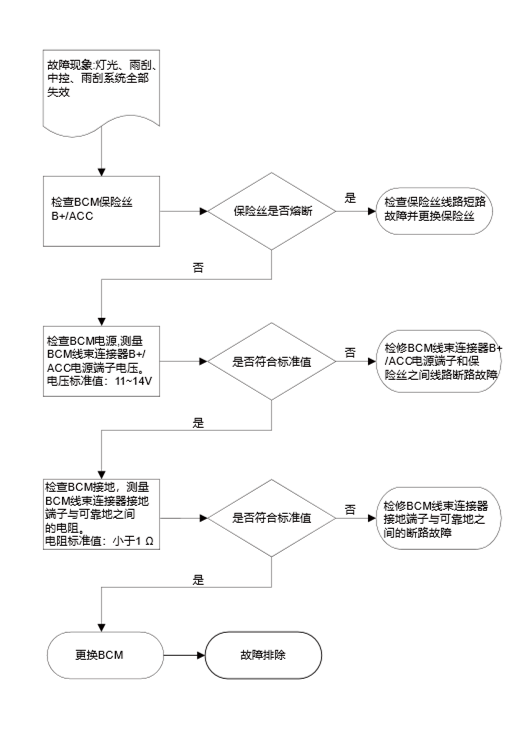
M05 BCM
C1
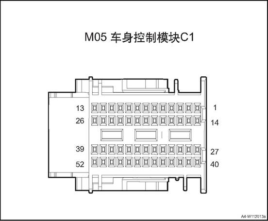
|
Connector No. |
Connector pin |
Wire Color |
Wire Diameter |
Pin Definition |
|
M05 |
1 |
B/W |
0.35 |
Rear view mirror folding switch |
|
M05 |
2 |
R/B |
0.35 |
EPB Switch Indicator Lamp (reserve) |
|
M05 |
3 |
R/Y |
0.35 |
Hazard warning lamp backlight |
|
M05 |
4 |
G/W |
0.5 |
P gear switch(CVT/DCT) |
|
M05 |
5 |
Br/V |
0.35 |
Position lamp switch |
|
M05 |
6 |
O/G |
0.5 |
IG1 feedback signal |
|
M05 |
7 |
R/G |
0.5 |
ACCfeedback signal |
|
M05 |
8 |
Gr/R |
0.35 |
Front wiper control |
|
M05 |
9 |
Bl/O |
0.35 |
Left/Right turn lamp switch |
|
M05 |
10 |
B |
0.5 |
Signal GND 3 |
|
M05 |
13 |
V |
0.5 |
BCAN_L |
|
M05 |
14 |
Gr |
0.35 |
Electric child lock feedback_right |
|
M05 |
15 |
W/B |
0.35 |
Front wiper GND |
|
M05 |
17 |
Gr |
0.5 |
Clutch pedal SW(MT) |
|
M05 |
18 |
- |
0.35 |
Key signal |
|
M05 |
25 |
Gr/Br |
0.35 |
Power saving relay |
|
M05 |
26 |
P |
0.5 |
BCAN_H |
|
M05 |
29 |
Br/W |
0.5 |
Front water spraying switch |
|
M05 |
32 |
Gr |
0.35 |
High beam switch |
|
M05 |
33 |
G/B |
0.35 |
Rear fog lamp switch |
|
M05 |
34 |
Bl/B |
0.35 |
Automatic light switch |
|
M05 |
35 |
B/W |
0.35 |
Hazard warning lamp switch |
|
M05 |
36 |
G |
0.35 |
Low beam switch |
|
M05 |
37 |
G |
0.35 |
Front wiper intermittent time adjustment GND |
|
M05 |
38 |
Y/B |
0.35 |
Window relay enable |
|
M05 |
39 |
Br/O |
0.5 |
Backlight |
|
M05 |
41 |
Gr/W |
0.35 |
Central lock indicating lamp |
|
M05 |
42 |
R/G |
0.5 |
Neutral position signal |
|
M05 |
44 |
G/R |
0.35 |
AUTOHOLD indicator (reserve) |
|
M05 |
45 |
Br/W |
0.35 |
Overtaking lamp switch |
|
M05 |
46 |
Br/O |
0.5 |
Reversing switch(MT) |
|
M05 |
47 |
R/W |
0.35 |
Front wiper intermittent time adjustment |
|
M05 |
50 |
O |
0.5 |
PCAN_H |
|
M05 |
51 |
Y |
0.5 |
PCAN_L |
|
M05 |
52 |
G/W |
0.35 |
Rear Defrost Relay |
F01 BCM
C2
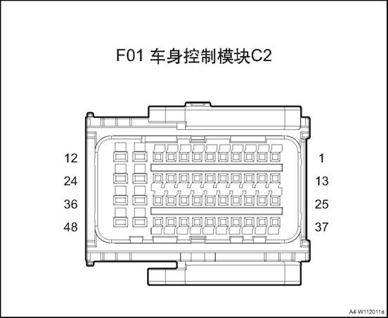
|
Connector No. |
Connector pin |
Wire Color |
Wire Diameter |
Pin Definition |
|
F01 |
1 |
Gr/Y |
0.35 |
Left Rear Door State |
|
F01 |
2 |
Lg/Bl |
0.35 |
Right Rear Door State |
|
F01 |
3 |
G/O |
0.35 |
Tail Door State |
|
F01 |
4 |
Lg |
0.35 |
Key signal |
|
F01 |
5 |
G |
0.35 |
Tail door unlocking switch |
|
F01 |
7 |
Lg/W |
0.35 |
Central control signal |
|
F01 |
8 |
B |
0.5 |
Signal GND 4 |
|
F01 |
10 |
- |
0.5 |
Mechanical key background |
|
F01 |
11 |
Gr/B |
0.5 |
Rear fog lamp |
|
F01 |
12 |
Lg |
0.5 |
Inner roof lamp |
|
F01 |
13 |
Br |
0.5 |
Brake light switch |
|
F01 |
14 |
O |
0.35 |
Electric child-lock lock |
|
F01 |
17 |
Gr/R |
0.35 |
Low Speed Relay of Front Wiper |
|
F01 |
18 |
Br/O |
0.35 |
High Beam Relay |
|
F01 |
21 |
Bl/B |
0.5 |
Front Windscreen Wiper Return Switch |
|
F01 |
23 |
Y/R |
0.5 |
Position Lamp |
|
F01 |
24 |
G/R |
0.5 |
Left turn light |
|
F01 |
25 |
Bl/B |
0.35 |
High brake lamp |
|
F01 |
27 |
Lg/B |
0.35 |
Co-pilot door state |
|
F01 |
28 |
L/R |
0.35 |
Welcome lamp output |
|
F01 |
31 |
Lg |
0.35 |
High Speed Relay of Front Wiper |
|
F01 |
33 |
W |
0.35 |
Electric child lock feedback_left |
|
F01 |
34 |
O |
0.5 |
LIN1 |
|
F01 |
35 |
Bl/R |
0.5 |
Right turn light |
|
F01 |
36 |
Br/Bl |
0.5 |
Reversing lamp +PDC+VRR |
|
F01 |
39 |
Lg/Bl |
0.35 |
Driver’s door state |
|
F01 |
41 |
Br/Bl |
0.35 |
Low Beam Relay |
|
F01 |
42 |
W/B |
0.35 |
Warning Horn Relay |
|
F01 |
46 |
O/G |
0.5 |
LIN2 |
|
F01 |
47 |
G/O |
0.5 |
Left daytime running lamp |
|
F01 |
48 |
G/Y |
0.5 |
Brake lamp |
M02 BCM
C3
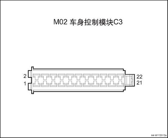
|
Connector No. |
Connector pin |
Wire Color |
Wire Diameter |
Pin Definition |
|
M02 |
1 |
R/Y |
0.5 |
BCM power 1 |
|
M02 |
2 |
Br/W |
0.5 |
Tail door unlocking power |
|
M02 |
3 |
P |
1.0 |
BCM power 2 |
|
M02 |
4 |
Gr |
0.5 |
Tail door open motor |
|
M02 |
5 |
Y/G |
0.5 |
Right daytime running lamp |
|
M02 |
6 |
Br/W |
0.5 |
Front water spray motor power |
|
M02 |
7 |
B |
0.5 |
Signal GND 1 |
|
M02 |
9 |
B |
0.5 |
Signal GND 2 |
|
M02 |
10 |
R/Bl |
0.5 |
Front water spray motor |
|
M02 |
12 |
P |
0.5 |
Rear view mirror folding |
|
M02 |
14 |
W |
1.0 |
Door lock power |
|
M02 |
16 |
Bl/O |
0.5 |
Rear view mirror unfolding |
|
M02 |
18 |
G |
0.75 |
Lock signal |
|
M02 |
20 |
P |
0.75 |
Unlock signal |
|
M02 |
22 |
B |
1.5 |
Power Supply GND |
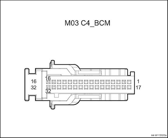
|
Connector No. |
Connector pin |
Wire Color |
Wire Diameter |
Pin Definition |
|
M03 |
3 |
Gr/Y |
0.35 |
Driver door inching switch |
|
M03 |
4 |
Y/O |
0.5 |
Central control lock switch |
|
M03 |
5 |
Y |
0.5 |
Central control lock switch |
|
M03 |
7 |
B |
0.5 |
Signal GND 5 |
|
M03 |
8 |
V |
0.5 |
Engine start button 1 |
|
M03 |
9 |
Bl/R |
0.5 |
Engine start button 2 |
|
M03 |
11 |
P/W |
0.5 |
Start button red indicator |
|
M03 |
12 |
P |
0.5 |
Start button green indicator |
|
M03 |
13 |
Br/W |
0.5 |
Start button backlight |
|
M03 |
15 |
G/O |
0.5 |
IG1 relay |
|
M03 |
18 |
Gr/G |
0.35 |
Standby antenna + |
|
M03 |
19 |
Gr/W |
0.35 |
Standby antenna - |
|
M03 |
20 |
Br |
0.35 |
Left front door handle + |
|
M03 |
21 |
Br/B |
0.35 |
Left front door handle - |
|
M03 |
22 |
Gr/Y |
0.35 |
Front low-frequency antenna + |
|
M03 |
23 |
Gr |
0.35 |
Front low-frequency antenna - |
|
M03 |
24 |
Bl/R |
0.35 |
Rear low-frequency antenna + |
|
M03 |
25 |
Y/W |
0.35 |
Rear low-frequency antenna - |
|
M03 |
26 |
Bl/B |
0.35 |
Rear bumper low-frequency antenna + |
|
M03 |
27 |
Y/B |
0.35 |
Rear bumper low-frequency antenna - |
|
M03 |
32 |
Br/W |
0.5 |
ACC relay |
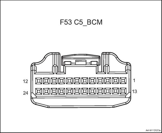
|
Connector No. |
Connector pin |
Wire Color |
Wire Diameter |
Pin Definition |
|
F53 |
2 |
R/B |
0.5 |
Ground lamp(left) |
|
F53 |
4 |
Gr/B |
0.5 |
Ground lamp(right) |
|
F53 |
19 |
G/R |
0.5 |
Left rear turn lamp signal |
|
F53 |
20 |
Bl/R |
0.5 |
Right rear turn lamp signal |
Power tail door controller 1 diagram
F28
Power Tail Door Controller1
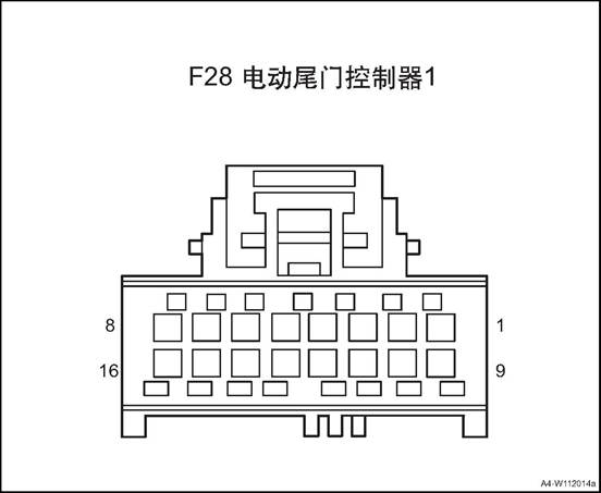
|
Connector No. |
Connector pin |
Wire Color |
Wire Diameter |
Pin Definition |
|
F28 |
2 |
Br/B |
0.35 |
Delay off indicator |
|
F28 |
3 |
G/Bl |
0.35 |
Tail door lower switch |
|
F28 |
4 |
Gr |
0.35 |
Self priming reset signal |
|
F28 |
5 |
G/Bl |
0.35 |
Half lock position signal |
|
F28 |
6 |
Bl/Y |
0.35 |
Half lock position signal switch |
|
F28 |
7 |
Y |
0.5 |
BCAN_L |
|
F28 |
9 |
Bl/R |
0.5 |
Electric unlock motor |
|
F28 |
12 |
V/G |
0.35 |
Driver’s side switch |
|
F28 |
13 |
R/O |
0.5 |
IG1 signal |
|
F28 |
14 |
Br |
0.35 |
Delayed close control switch |
|
F28 |
15 |
O |
0.5 |
BCAN_H |
|
F28 |
16 |
Gr/G |
0.35 |
Signal GND |
Power tail door controller 2 diagram
F29
Power Tail Door Controller 2
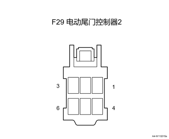
|
Connector No. |
Connector pin |
Wire Color |
Wire Diameter |
Pin Definition |
|
F29 |
1 |
G |
1 |
Self priming motor flip |
|
F29 |
2 |
Y |
1 |
Self priming motor pickup |
|
F29 |
3 |
G/B |
2.5 |
30A power input |
|
F29 |
4 |
B/W |
0.5 |
10A power input |
|
F29 |
6 |
B |
2.5 |
Power Supply GND |
![]()
Power tail door controller 3 diagram
![]()
|
Connector No. |
Connector pin |
Wire Color |
Wire Diameter |
Pin Definition |
|
F30 |
1 |
Bl |
1.5 |
Left electric stay bar open control |
|
F30 |
2 |
W |
1.5 |
Left electric stay bar open control |
|
F30 |
3 |
Bl |
1.5 |
Right electric stay bar open control |
|
F30 |
4 |
W |
1.5 |
Right electric stay bar open control |
|
F30 |
7 |
Bl/G |
0.35 |
Right electric stay bar Hall signal 1 |
|
F30 |
8 |
Bl/R |
0.35 |
Hall sensor power |
|
F30 |
9 |
Bl/G |
0.35 |
Left electric stay bar Hall signal 1 |
|
F30 |
10 |
Bl/Y |
0.35 |
Left electric stay bar Hall signal 2 |
|
F30 |
11 |
Bl/V |
0.35 |
Hall sensor circuit |
|
F30 |
12 |
Bl/Y |
0.35 |
Right electric stay bar Hall signal 2 |
|
F30 |
13 |
G |
0.5 |
Horn output |
|
F30 |
14 |
Gr |
0.5 |
Horn circuit |
P07 Kick
sensor
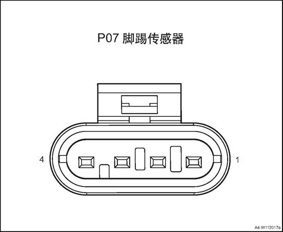
|
Connector serial number |
Connector pin |
Wire Color |
Wire Diameter |
Pin Definition |
|
P07 |
2 |
B |
0.5 |
GND |
|
P07 |
3 |
O |
0.5 |
LIN wire |
|
P07 |
4 |
B/W |
0.5 |
Power |
Power window anti-pinch module C1 diagram
F04
Power window anti-pinch module C1
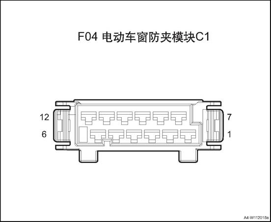
|
Connector No. |
Connector pin |
Wire Color |
Wire Diameter |
Pin Definition |
|
F04 |
1 |
P |
1.5 |
APM constant power 1 |
|
F04 |
2 |
O |
1.5 |
APM constant power 2 |
|
F04 |
3 |
B |
1.5 |
Ground(large current) |
|
F04 |
4 |
B |
1.5 |
Ground(large current) |
|
F04 |
5 |
Br |
1.5 |
Right rear down |
|
F04 |
6 |
G |
1.5 |
Right rear up |
|
F04 |
7 |
Bl |
1.5 |
Left front up |
|
F04 |
8 |
Br |
1.5 |
Left front down |
|
F04 |
9 |
G/W |
1.5 |
Right front up |
|
F04 |
10 |
Bl |
1.5 |
Right front down |
|
F04 |
11 |
B/G |
1.5 |
Left rear up |
|
F04 |
12 |
Br/Y |
1.5 |
Left rear down |
|
F04 |
12 |
R |
1.5 |
Left rear down |
Power window anti-pinch module C2 diagram
F03
Power window anti-pinch module C2
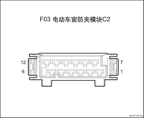
|
Connector No. |
Connector pin |
Wire Color |
Wire Diameter |
Pin Definition |
|
F03 |
1 |
O |
0.5 |
BCAN_H |
|
F03 |
2 |
Y |
0.5 |
BCAN_L |
|
F03 |
3 |
Gr |
0.5 |
ACC signal |
|
F03 |
5 |
Lg |
0.35 |
Sub-window lock button input |
|
F03 |
6 |
W/B |
0.35 |
Sub-window right rear lift input |
|
F03 |
7 |
O/B |
0.35 |
Main window right rear lift input |
|
F03 |
8 |
Br |
0.35 |
Sub-window left rear lift input |
|
F03 |
9 |
G/W |
0.35 |
Main window left rear lift input |
|
F03 |
10 |
Bl |
0.35 |
Sub-window right front lift input |
|
F03 |
11 |
B/G |
0.35 |
Main window right front lift input |
|
F03 |
13 |
G/W |
0.35 |
Main window left front lift input |
|
F03 |
15 |
Gr/G |
0.5 |
Ground(small current) |
|
F03 |
16 |
B/W |
0.5 |
APM constant power 3 |
|
F03 |
27 |
R/O |
0.35 |
Passenger invalid indicator |
|
F03 |
30 |
R/O |
0.5 |
IGN signal |
Ambient Lamp Controller diagram
M29
Ambient Lamp Controller
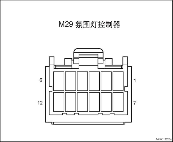
|
Connector No. |
Connector pin |
Wire Color |
Wire Diameter |
Pin Definition |
|
M29 |
1 |
W |
0.5 |
Ambient 12V power output |
|
M29 |
2 |
P |
0.5 |
ACC signal |
|
M29 |
3 |
Y |
0.5 |
BCAN_L |
|
M29 |
4 |
O |
0.5 |
BCAN_H |
|
M29 |
5 |
Gr |
0.35 |
LIN signal |
|
M29 |
7 |
Br |
0.75 |
Node controller 12V input |
|
M29 |
8 |
Br/R |
0.5 |
Front door right audio |
|
M29 |
9 |
G |
0.5 |
Front door right audio |
|
M29 |
10 |
V |
0.5 |
Front door left audio |
|
M29 |
11 |
Br/B |
0.5 |
Front door left audio |
|
M29 |
12 |
B |
0.5 |
GND |
M24
Wireless Charging
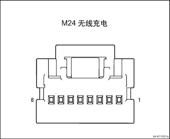
|
Connector serial number |
Connector pin |
Wire Color |
Wire Diameter |
Pin Definition |
|
M24 |
1 |
R/G |
0.75 |
ACC signal |
|
M24 |
2 |
B |
0.5 |
GND |
|
M24 |
3 |
Y |
0.5 |
BCAN_L |
|
M24 |
4 |
O |
0.5 |
BCAN_H |
1. Open the engine cover
2. Disconnect the battery negative cable.
3. Dismantle the dashboard left end cover assembly, refer to the “dashboard left end cover assembly”.
4. Disassemble the driver's side lower guard plate assembly
5. Remove bodywork control module.
![]() 1) Disconnect BCM wire harness
connector.
1) Disconnect BCM wire harness
connector.
![]() 2) Remove the 3 bolts fixing the
BCM.
2) Remove the 3 bolts fixing the
BCM.
3) Take off the BCM.
Install the body controller assembly
1) Put the BCM at installation position.
![]() 2) Install and tighten the 3 fixing
bolts of BCM
2) Install and tighten the 3 fixing
bolts of BCM
Tightening torque 6 ~ 9N·m
![]() 3) Connect BCM wire harness
connector.
3) Connect BCM wire harness
connector.
Install bottom guard plate on driver’s side
3. Install the dashboard left end cover assembly
4). Connect the battery negative cable.
5. Close the engine compartment cover
1. Open the engine cover
2. Disconnect the battery negative cable.
3. Remove the C pillar lower guard plates and luggage compartment guard plate. Refer to the “C pillar lower guard plate” and the “luggage compartment guard plate”.
4. Dismantle the tail door controller assembly.
![]() 1) Disconnect tail door controller
assembly wire harness connector 1.
1) Disconnect tail door controller
assembly wire harness connector 1.
2) Dismantle the 2 nuts fixing the tail door controller assembly.
3) Take off the tail door controller assembly.
1. Install the tail door controller assembly.
1) Put the tail door controller assembly at installation position.
2) Mount and tighten the 2 fixing nuts of the tail door controller assembly.
Tightening torque 8 ~ 10N · m
3) Connect tail door controller assembly wire harness connector 1.
2. Install the right C pillar lower guard plate and luggage compartment guard plate.
![]() 3. Connect the battery negative cable.
3. Connect the battery negative cable.
4. Close the engine compartment cover.
1. Open the engine cover
2. Disconnect the battery negative cable.
3. Dismantle the glove box assembly refer to glove box assembly
4. Dismantle the ambient lamp controller.
![]() 1) Disconnect the ambient lamp
controller wire harness connector 1.
1) Disconnect the ambient lamp
controller wire harness connector 1.
2) Remove the 2 fixing bolts of the ambient lamp controller.
3) Take off the ambient lamp controller.
1. Install the ambient lamp controller.
![]() 1) Put the ambient lamp controller
at installation position.
1) Put the ambient lamp controller
at installation position.
2) Mount and tighten the 2 fixing bolts of the ambient lamp controller
Tightening torque 7 ~ 9N·m
3) Connect the ambient lamp controller wire harness connector 1.
2. Install glove box assembly
3. Connect the battery negative cable.
4. Close the engine compartment cover.
1. Open the engine cover
2. Disconnect the battery negative cable.
3. Remove the front right seat assembly See front right seat assembly
4. Dismantle the power window anti-pinch controller.
1) Remove the maintenance carpet.
2) Disconnect the power window anti-pinch controller wire harness connector.
![]()
3) Dismantle the 2 fixing nuts of the power window anti-pinch controller.
![]() 4) Take off the power window
anti-pinch controller.
4) Take off the power window
anti-pinch controller.
1. Install the power window anti-pinch controller.
1) Put the power window anti-pinch controller at the installation position
2) Mount and tighten the 2 fixing nuts of the power window anti-pinch controller.
Tightening torque 8 ~ 10N · m
![]()
3) Connect the power window anti-pinch controller wire harness connector.
![]() 4) Cover the maintenance carpet.
4) Cover the maintenance carpet.
2. Install the front right seat assembly.
3. Connect the battery negative cable.
4. Close the engine compartment cover.
1. Open the engine cover
2. Disconnect the battery negative cable.
3. Remove the rear bumper assembly. Refer to the rear bumper assembly
4. Dismantle the kick sensor&controller assembly.
1) Disconnect the kick sensor&controller assembly wire harness connector 1.
2) Dismantle the 2 fixing bolts 2 of the kick sensor&controller assembly.
![]() 3) Take off the kick
sensor&controller assembly.
3) Take off the kick
sensor&controller assembly.
1. Install the kick sensor&controller assembly.
1) Put the kick sensor&controller assembly at installation position.
2) Mount and tighten the 2 fixing bolts 2 of the kick sensor&controller assembly.
3) Connect the kick sensor&controller assembly wire harness connector 1.
![]() 2. Install rear bumper assembly
2. Install rear bumper assembly
3. Connect the battery negative cable.
4. Close the engine compartment cover.
1. Open the engine cover
2. Disconnect the battery negative cable.
3. Remove the rear bumper assembly. Refer to the rear bumper assembly
4. Dismantle the kick sensor antenna
![]() 1) Disconnect the kick sensor
antenna wire harness connector 1.
1) Disconnect the kick sensor
antenna wire harness connector 1.
2) Take off the the kick sensor antenna.
1. Install the kick sensor antenna.
![]() 1) Put the kick sensor antenna at
installation position.
1) Put the kick sensor antenna at
installation position.
2) Connect the kick sensor antenna wire harness connector 1.
2. Install rear bumper assembly
3. Connect the battery negative cable.
4. Close the engine compartment cover.
1. Open the engine cover
2. Disconnect the battery negative cable.
3. Disassemble tail door trim panel assembly. See the “tail door trim panel assembly”.
4. Remove the buzzer
![]() 1) Disconnect the buzzer wire
harness connector 1.
1) Disconnect the buzzer wire
harness connector 1.
2) Dismantle the 2 fixing screws of the buzzer.
3) Remove the buzzer
1. Install the buzzer
![]() 1) Put the buzzer at installation
position.
1) Put the buzzer at installation
position.
2)
Install the 2 fixing screws of the buzzer. Tightening torque 7 ~ 9N·m
3) Connect the buzzer wire harness connector 1.
2. Install tail door trim panel assembly
3. Connect the battery negative cable.
4. Close the engine compartment cover.
1. Open the engine cover
2. Disconnect the battery negative cable.
3. Dismantle the front storage box, refer to “front storage box assembly”.
4. Dismantle the wireless charging module.
![]() 1)Disconnect the wireless charging
module wire harness connector 1.
1)Disconnect the wireless charging
module wire harness connector 1.
2) Install the 4 screws 2 fixing the wireless charging module
3) Take off the wireless charging module.
1. Install the wireless charging module.
![]() 1) Put the wireless charging module
at installation position.
1) Put the wireless charging module
at installation position.
2) Install the 4 screws 2 fixing the wireless charging module
3) Connect the wireless charging module wire harness connector 1.
2. Install the front storage box assembly
3. Connect the battery negative cable.
4. Close the engine compartment cover.
The rearview mirror switch is used for the four-way adjustment of the rearview mirror, which is located at the driver side lower guard plate. Backlight and headlight height adjustment switch is used for the beam height of headlights, there are 7 gears: 0-6, located at the driver side lower guard plate. Central control switch group includes hazard warning lamp, ESC OFF switch, located on the sub-dash.
The glass regulator switch is used to control the window up and down. The driver's switch can control the other three doors’ window up and down, and realize the functions of window locking and door locking. Located at the four doors’ armrest panel.
![]()
1. Central control switch group
2. Left lower switch group
3. Glass regulator master control switch
4. Combination switch
5. Clock spring
6. Tail door outer switch
7. Tail door switch bracket
|
No. |
Item |
Specification |
Remark |
|
1 |
Rated voltage/working voltage range |
DC 12V/9V—16V |
|
|
2 |
Rated load/Max load |
100mA/150mA |
|
Backlight and headlight height adjustment switch
|
No. |
Item |
Specification |
Remark |
|
1 |
Rated voltage/working voltage range |
DC 12V/9V—16V |
|
|
2 |
Rated load |
<10mA |
|
Glass regulator switch
|
No. |
Item |
Specification |
Remark |
|
1 |
Rated voltage/working voltage range |
DC 12V/9V—16V |
|
|
2 |
Rated load |
<10mA |
Four-window one button regulator |
|
3 |
Rated load |
<10A |
Driver’s side one button regulator |
|
No. |
Item |
Torque (N·m) |
|
1 |
Combination switch fixing screws |
1~2 |
|
2 |
Tail door switch bracket screws |
1~2 |
|
Fault symptom |
Possible Cause of Malfunction |
Solution |
|
Mirror regulating function invalid |
Circuit fault |
1. Check harness connector for looseness. |
|
2. Use multimeter to check the continuity of the switch according to the logic diagram. |
||
|
3. Check other circuits and the rearview mirror control module |
Backlight and headlight height adjustment switch
|
Fault symptoms |
Possible Cause of Malfunction |
Solution |
|
Headlight height adjustment invalid |
Circuit fault |
1. Check harness connector for looseness. 2. Use multimeter to check the output voltage of the switch according to the logic diagram. 3. Check other circuits and the headlight module. |
|
Fault symptoms |
Possible Cause of Malfunction |
Solution |
|
Window lifting function failure |
Circuit fault |
1. Check harness connector for looseness. 2. Use multimeter to check the continuity of the switch according to the logic diagram. 3. Check other circuits and the anti-pinch module and motor. |
|
Window lock failure |
Circuit fault |
1. Check harness connector for looseness. 2. Use multimeter to check the continuity of the switch according to the logic diagram. 3. Check other circuits and the anti-pinch module and motor. |
|
Door lock failure |
1. Check harness connector for looseness. 2. Use multimeter to check the continuity of the switch according to the logic diagram. 3. Check other circuits and BCM. |
Combination Switch - Lamp Diagram
M06
Combination Switch-Lamp

|
Connector No. |
Connector pin |
Wire Color |
Wire Diameter |
Pin Definition |
|||||
|
M06 |
1 |
B |
0.35 |
Switch ground |
|||||
|
|
3 |
Br/V |
0.35 |
Small lamp |
|
|||||
|
M06 |
4 |
Bl/B |
0.35 |
Auto headlight |
|
|||||
|
M06 |
5 |
G |
0.35 |
Headlight (low-beam) |
|
|||||
|
M06 |
7 |
G/B |
0.35 |
Rear fog lamp |
|
|||||
|
M06 |
8 |
Br/W |
0.35 |
Overtaking lamp |
|
|||||
|
M06 |
10 |
Gr |
0.35 |
High Beam |
|
|||||
|
M06 |
12 |
Bl/O |
0.35 |
Turn lamp + |
|
|||||
|
M06 |
13 |
G |
0.35 |
Turn lamp - |
|
|||||
Combination Switch - Wiper Diagram
![]()
|
Connector No. |
Connector pin |
Wire Color |
Wire Diameter |
Pin Definition |
|
M13 |
6 |
B |
0.5 |
Switch ground |
|
M13 |
7 |
Br/W |
0.5 |
Front washer |
|
M13 |
8 |
Gr/R |
0.35 |
Front wiper + |
|
M13 |
9 |
W/B |
0.35 |
Front wiper - |
|
M13 |
12 |
R/W |
0.35 |
Intermittent adjustment + |
|
M13 |
13 |
G |
0.35 |
Intermittent adjustment - |
M07
Clock Spring_Horn
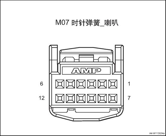
|
Connector No. |
Connector pin |
Wire Color |
Wire Diameter |
Pin Definition |
|
M07 |
2 |
R |
0.5 |
Entertainment signal 1 |
|
M07 |
3 |
Bl/O |
0.5 |
Entertainment signal 2 |
|
M07 |
4 |
Bl/G |
0.5 |
Public terminal |
|
M07 |
5 |
R |
0.5 |
ACC power(adaptive cruise control) |
|
M07 |
5 |
O/R |
0.5 |
Cruise control + |
|
M07 |
6 |
O/G |
0.5 |
LIN signal (adaptive cruise control) |
|
M07 |
6 |
Br |
0.5 |
Cruise control - |
|
M07 |
8 |
Br/O |
0.35 |
Backlight + |
|
M07 |
9 |
B |
0.35 |
GND |
|
M07 |
10 |
Bl/Br |
0.35 |
Instrument signal + |
|
M07 |
11 |
Gr/R |
0.35 |
Instrument signal - |
|
M07 |
12 |
W/B |
0.35 |
Horn |
M08
Clock Spring-Airbag
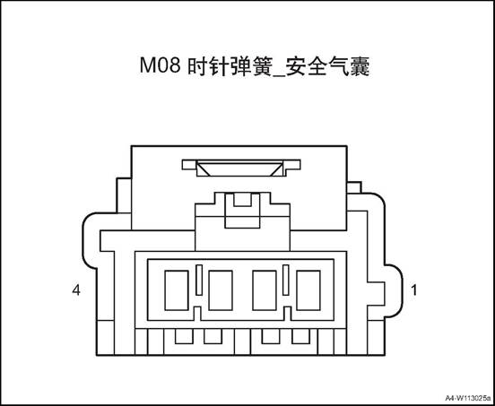
|
Connector No. |
Connector pin |
Wire Color |
Wire Diameter |
Pin Definition |
|
M08 |
1 |
G |
0.5 |
Driver airbag |
|
M08 |
2 |
G/R |
0.5 |
Driver airbag |
△Attention: Before removal, turn the steering wheel to align the wheels and turn off the start switch to lock the steering wheel.
1. Open the engine cover
2. Disconnect the battery negative cable.
3. Disassemble the driver's airbag assembly.Refer to the “driver's airbag assembly”.
4. Remove the steering wheel assembly, refer to the “Steering Wheel Assembly".
5. Remove the instrument cluster cover assembly, refer to the instrument cluster cover assembly
6. Disassemble the steering column housing lower shell, refer to “steering column lower shell”.
7. Remove the clock spring
![]() 1) Loosen the 3 clips, and remove
the clock spring.
1) Loosen the 3 clips, and remove
the clock spring.
![]() 2). Disconnect the clock spring
wire harness connector.
2). Disconnect the clock spring
wire harness connector.
Assemble the clock spring
![]() 1) Connect front roof lamp assembly
harness connector.
1) Connect front roof lamp assembly
harness connector.
△Attention: First, turn the clock spring clockwise to the limit position, then turn it back to the limit position to determine the total number of turns, and finally turn back to the middle position.
![]() 2) Install the clock spring to the
steering column, and clamp it firmly.
2) Install the clock spring to the
steering column, and clamp it firmly.
2. Install the steering column housing lower shell
3. Install the instrument cluster cover assembly
4. Install the steering wheel
5. Assemble driver safety airbag assembly.
6). Connect the battery negative cable.
Close the engine cover.
1. Open the engine cover
2. Disconnect the battery negative cable.
3. Disassemble the driver's airbag assembly.Refer to the “driver's airbag assembly”.
4. Remove the steering wheel assembly, refer to the “Steering Wheel Assembly".
5. Remove the instrument cluster cover assembly, refer to the instrument cluster cover assembly
6. Disassemble the steering column housing lower shell, refer to “steering column lower shell”.
7. Disassemble the clock spring.Refer to “Clock Spring”.
8. Remove the combination switch assembly.
![]() 1) Dismantle the 2 screws fixing
the combination switch assembly.
1) Dismantle the 2 screws fixing
the combination switch assembly.
![]() 2) Disconnect the combination
switch assembly wire harness connector.
2) Disconnect the combination
switch assembly wire harness connector.
Remove the combination switch assembly.
1. Install the combination switch assembly
![]() 1) Put the combination switch
assembly at installation position.
1) Put the combination switch
assembly at installation position.
2) Connect the combination switch assembly wire harness connector.
![]() 3) Install the 2 screws fixing the
combination switch assembly.
3) Install the 2 screws fixing the
combination switch assembly.
Tightening torque 1~2N·m
2. Assemble the clock spring
3. Install the steering column housing lower shell
4. Install the instrument cluster cover assembly
5. Install steering wheel assembly
6. Assemble driver safety airbag assembly.
7). Connect the battery negative cable.
8. Close the engine compartment cover
1. Operate the combination switch light control handle and test the working condition of all lights and switches.
2. When the light control handle is in OFF gear, all exterior lights and night lights of electrical equipment in the vehicle shall be extinguished.
3. When the light control handle is in the small light gear, position lights, front and rear position lights, license plate lamps, instrument lighting and all electrical equipment in the vehicle at night shall be on. If the vehicle is in driving state, the side position lamp shall also be on
4. When the light control handle is in the small light gear, when the front (rear) fog lamp switch is pressed, all front (rear) fog lights should be on.
5. When the light control handle is in headlight gear, the headlight low beam is on, while all the small lights are on. At this time, turn the handle down by 6 ° and the high beam of the headlight is on. Turn the handle back to its original position, and then turn it up by 6 ° to turn the high beam on instantaneously, release the handle, the switch will automatically return.
6. When the light lever is turned 15° forwards (rearward), all right (left) turn signals start to flash and the right (left) turn indicator light on the instrument starts flashing and the handle stops returning to its original position. Rotate the handle forward (after) 9°, right (left) turn signal light flashes, the handle automatically resets after release hand.
7. Press the alarm switch, all turn signals should be flashing at the same time, the left and right turn indicators on the instrument also flash.
8. Operate combination switch wiper/ washing functions to check wiper and washer working state.
1) When the handle is in OFF position, the wiper and washer does not work
2) When the handle is in MIST position, the wiper makes inching action. When the force disappears, the handle is reset and the wiper stops working.
3) When the handle is in INT gear, the wiper rod moves in a regular interval.
4) Turn the intermittent time adjustment knob to change the wiper speed between FAST and SLOW.
5) When the handle is in the LO position, the wiper moves continuously at a low speed.
6) When the handle is in the HI position, the wiper moves continuously at a high speed.
7) When the handle is lifted upward, the front washing nozzle sprays water on the front windscreen. At the same time, when the front wiper acts, the force disappears, the handle automatically returns to the position, and the washer and wiper stop working.
8) Rotate the knob at the end of the handle to INT, the rear wiper starts running at a low speed.
9) Rotate the knob at the end of the handle to ON, the rear wiper starts running at a high speed.
10) When the handle is pressed down, the rear washing nozzle sprays water on the rear windscreen. When the handle is released, it will return automatically, and the water spray and wiper will stop working.
1. Open the engine cover
2. Disconnect the battery negative cable.
![]() 3. Remove the rearview mirror switch
3. Remove the rearview mirror switch
1) Disassemble the driver side lower guard plate.
![]() 2) Disconnect the rearview mirror
switch wire harness connector.
2) Disconnect the rearview mirror
switch wire harness connector.
3) Take off the rearview mirror switch.
1. Install the rearview mirror switch.
![]() 1) Put the rearview mirror switch
at installation position.
1) Put the rearview mirror switch
at installation position.
2) Connect the rearview mirror switch wire harness connector.
![]() 3) Assemble the driver side lower
guard plate.
3) Assemble the driver side lower
guard plate.
2). Connect the battery negative cable.
3. Close the engine compartment cover
1. Open the engine cover
2. Disconnect the battery negative cable.
3. Dismantle the glass regulator master control switch
1) Take out the glass regulator master control switch storage box, remove the one screw.
![]() 2) Pry off the glass regulator
master control switch.
2) Pry off the glass regulator
master control switch.
△Attention Do not damage the door trim panel.
3) Disconnect the glass regulator master control switch wire harness connector.
4) Take off the glass regulator master control switch
![]()
1. Install the glass regulator master control switch
1) Connect the glass regulator master control switch wire harness connector.
![]()
2) Install the driver’s side door window regulating switch assembly into the front door trim assembly.
![]() 3) Install the one screw of the
glass regulator master control switch.
3) Install the one screw of the
glass regulator master control switch.
4) install the the storage box.
△ Note: After installation, check if the functions of each button are normal. If not normal or unable to work, it should be re-installed or replaced.
2). Connect the battery negative cable.
3. Close the engine compartment cover
1. Open the engine cover
2. Disconnect the battery negative cable.
3. Dismantle the glass regulator master control switch
![]() 1) Take out the glass regulator
switch storage box, remove the one screw.
1) Take out the glass regulator
switch storage box, remove the one screw.
2) Pry off the glass regulator switch.
△Attention Do not damage the door trim panel.
![]() 3) Disconnect the glass regulator
switch wire harness connector.
3) Disconnect the glass regulator
switch wire harness connector.
4) Take off the glass regulator switch.
1. Install the glass regulator switch.
![]() 1) Connect the glass regulator
switch wire harness connector.
1) Connect the glass regulator
switch wire harness connector.
![]() 2) Install the glass regulator
switch on the rear door inner trim panel.
2) Install the glass regulator
switch on the rear door inner trim panel.
3) Install the one screw of the glass regulator switch.
4) install the the storage box.
△ Note: After installation, check if the function of each button is normal. If not normal or unable to work, it should be re-installed or replaced.
2). Connect the battery negative cable.
3. Close the engine compartment cover
Ⅷ Central Control Switch Group
1. Open the engine cover
2. Disconnect the battery negative cable.
3. Remove sub-dash panel upper trim assembly, refer to the “sub-dash panel upper trim assembly”.
4. Remove the central control switch group.
1) Pry up the central control switch group
![]() 2) Remove the central control
switch group.
2) Remove the central control
switch group.
1. Install the central control switch group
![]() 1) Put the central control switch
group at the installation position
1) Put the central control switch
group at the installation position
2) Install the central control switch group
2. Install the sub-dash panel upper trim assembly
3. Connect the battery negative cable.
4. Close the engine compartment cover.
1. Open the engine cover
2. Disconnect the battery negative cable.
3. Remove the driver airbag. See the “driver airbag”.
![]() 4. Dismantle the steering wheel multifunction switch.
4. Dismantle the steering wheel multifunction switch.
1) Pry up the steering wheel multifunction switch assembly
![]() 1. Install the steering wheel
multifunction switch
1. Install the steering wheel
multifunction switch
1). Press the steering wheel multifunction switch into the steering wheel.
2. Install the driver's airbag
3. Connect the battery negative cable.
4. Close the engine compartment cover.
1 Open the engine compartment cover.
2. Disconnect the battery negative cable.
3. Remove electronic parking switch.
1) Pry up the upper trim panel assembly of sub dashboard
![]() 2) Disconnect the electronic
parking switch wire harness connector.
2) Disconnect the electronic
parking switch wire harness connector.
![]() 3) Remove the 2 screws for
electronic parking switch
3) Remove the 2 screws for
electronic parking switch
![]() 4) Take off the electronic Parking Switch
4) Take off the electronic Parking Switch
1. Install electronic parking switch.
![]() 1) Put the electronic parking
switch at installation position.
1) Put the electronic parking
switch at installation position.
![]() 2) Install the 2 screws for
electronic parking switch
2) Install the 2 screws for
electronic parking switch
Tightening torque 1~2N·m
![]() 3) Connect the electronic parking
switch wire harness connector.
3) Connect the electronic parking
switch wire harness connector.
4) Install the sub-dash panel upper trim assembly
2. Connect the battery negative cable.
3. Close the engine compartment cover
1. Open the engine cover
2. Disconnect the battery negative cable.
3. Dismantle the light adjusting switch.
![]() 1) Disassemble the driver side
lower guard plate.
1) Disassemble the driver side
lower guard plate.
![]() 2) Disconnect the light adjusting
switch wire harness connector.
2) Disconnect the light adjusting
switch wire harness connector.
3) Take off the light adjusting switch.
1. Install the light adjusting switch.
![]() 1) Put the light adjusting switch
at installation position.
1) Put the light adjusting switch
at installation position.
2) Disconnect the light adjusting switch wire harness connector.
![]() 3) Assemble the driver side lower
guard plate.
3) Assemble the driver side lower
guard plate.
2. Install the light adjusting switch.
3. Connect the battery negative cable.
4. Close the engine compartment cover.
1. Open the engine cover
2. Disconnect the battery negative cable.
3. Remove the left lower switch group
![]() 1) Disassemble the driver side
lower guard plate.
1) Disassemble the driver side
lower guard plate.
![]() 2) Disconnect the left lower switch
group wire harness connector.
2) Disconnect the left lower switch
group wire harness connector.
3) Take off the left lower switch group.
1. Install the left lower switch group.
![]() 1) Put the left lower switch group
at the installation position
1) Put the left lower switch group
at the installation position
2) Connect the left lower switch group wire harness connector.
![]() 3) Assemble the driver side lower guard
plate.
3) Assemble the driver side lower guard
plate.
2). Connect the battery negative cable.
3. Close the engine compartment cover
1. Open the engine cover
2. Disconnect the battery negative cable.
3. Disassemble tail door trim panel assembly. See the “tail door trim panel assembly”.
4. Dismantle the tail door outer switch.
![]() 1) Disconnect the tail door outer
switch wire harness connector.
1) Disconnect the tail door outer
switch wire harness connector.
![]() 2) Pry up tail door outer switch.
2) Pry up tail door outer switch.
1. Install the tail door outer switch.
![]() 1) Put the tail door outer switch
at installation position.
1) Put the tail door outer switch
at installation position.
![]() 2) Connect the tail door outer
switch wire harness connector.
2) Connect the tail door outer
switch wire harness connector.
2. Install tail door trim panel assembly
3. Connect the battery negative cable.
4. Close the engine compartment cover.
1. Open the engine cover
2. Disconnect the battery negative cable.
3. Disassemble tail door trim panel assembly. See the “tail door trim panel assembly”.
4. Dismantle the tail door outer switch. See the “tail door outer switch”.
5. Dismantle the tail door switch bracket.
![]() 1) Dismantle the tail door switch
bracket screws
1) Dismantle the tail door switch
bracket screws
2) Take off the tail door switch bracket
1. Install boot switch bracket
![]() 1) Put the tail door switch bracket
at installation position.
1) Put the tail door switch bracket
at installation position.
2) Install the tail door switch bracket screws
Tightening torque 1~2N·m
2. Install the tail door outer switch.
3. Install tail door trim panel assembly
4). Connect the battery negative cable.
5. Close the engine compartment cover
In addition to a cigarette lighter, the vehicle is also equipped with a spare power socket. The cigarette lighter and the standby power socket are installed under the central instrument panel. Both the cigarette lighter and the spare power socket are powered by ACC power. A light ring is also arranged on the seat of the cigarette lighter, which is convenient for use at night.
![]()
1. Multimedia Interface Assembly
2. 12V on-board power.
3. 5V USB Charger
|
No. |
Measure |
Normal Result |
Abnormal Result |
|
1 |
Press the cigarette lighter into its seat until you hear a clicking sound |
When the negative pole is power-on, the cigarette lighter will jump to the edge of the seat. |
The cigarette lighter does not work. |
|
2 |
|
The cigarette lighter lamp is on. |
The cigarette lighter lamp is off. |
The cigarette lighter does not work.
|
Step |
Measure |
Yes |
No |
|
1 |
Check whether the fuse is blown. |
Turn to step 4 |
Turn to step 2 |
|
2 |
Use a test light to connect the positive and negative ports of the cigar lighter to check if the test lamp is on |
Turn to step 5 |
Turn to step 3 |
|
3 |
If the cigarette lighter light is on |
Turn to step 6 |
Turn to step 7 |
|
4 |
Replace the fuse |
- |
To “system check” |
|
5 |
Replace the cigarette lighter |
- |
To “system check” |
|
6 |
Replace the cigarette light lamp |
- |
To “system check” |
|
7 |
Repair the circuit |
- |
To “system check” |
On-board power supply system check
|
No. |
Measure |
Normal Result |
Abnormal Result |
|
1 |
Put the vehicle external adapter to the on-vehicle power supply |
The adapter can supply power to the electrical equipment normally |
The on board power don’t work |
|
Step |
Measure |
Yes |
No |
|
1 |
Check whether the fuse is blown. |
Turn to step 3 |
Turn to step 2 |
|
2 |
Check wiring harness connector for looseness. |
Turn to step 4 |
Turn to step 5 |
|
3 |
Replace the fuse |
- |
To “system check” |
|
4 |
Repair the circuit |
- |
To “system check” |
|
5 |
Replace on board power |
- |
To “system check” |
|
No. |
Measure |
Normal Result |
Abnormal Result |
|
1 |
Insert the phone charge wire to the USB connector |
Phone can charge normally |
Phone can’t charge |
|
Step |
Measure |
Yes |
No |
|
1 |
Check whether the fuse is blown. |
Turn to step 3 |
Turn to step 2 |
|
2 |
Check wiring harness connector for looseness. |
Turn to step 4 |
Turn to step 5 |
|
3 |
Replace the fuse |
- |
To “system check” |
|
4 |
Repair the circuit |
- |
To “system check” |
|
5 |
Replace the USB charging interface |
- |
To “system check” |
1. Open the engine cover
2. Disconnect the battery negative cable.
△Warning: It takes At least 3 minutes until the discharge of energy storage capacitor in ACU is completed.
3. Dismantle the 12V on-board power.
![]() 1) Pry up the 12V on-board power.
1) Pry up the 12V on-board power.
![]() 2) Disconnect the 12V on-board
power wire harness connector.
2) Disconnect the 12V on-board
power wire harness connector.
1. Install the 12V on-board power.
![]() 1)Connect the 12V on-board power
wire harness connector.
1)Connect the 12V on-board power
wire harness connector.
![]() 2) Install the 12V on-board power.
2) Install the 12V on-board power.
2). Connect the battery negative cable.
3. Close the engine compartment cover
1. Open the engine cover
2. Disconnect the battery negative cable.
△Warning: It takes At least 3 minutes until the discharge of energy storage capacitor in ACU is completed.
3. Dismantle the multi-media interface
![]() 3) Pry up the multimedia interface
assembly
3) Pry up the multimedia interface
assembly
![]() 4) Disconnect multimedia interface
assembly harness connector.
4) Disconnect multimedia interface
assembly harness connector.
1. Install the multimedia interface assembly
![]() 1) Connect multimedia interface
assembly harness connector.
1) Connect multimedia interface
assembly harness connector.
![]() 2) Install the multimedia interface
assembly
2) Install the multimedia interface
assembly
2). Connect the battery negative cable.
3. Close the engine compartment cover
1. Open the engine cover
2. Disconnect the battery negative cable.
Remove sub-dash panel cover assembly See sub-dash panel cover assembly
4. Dismantle the 5V USB Charger
△Warning: It takes At least 3 minutes until the discharge of energy storage capacitor in ACU is completed.
1) Disconnect the 5V USB charger wire harness connector.
![]()
![]() 2) Pry up the 5V USB charger.
2) Pry up the 5V USB charger.
1. Install the 5V USB charger
![]() 1) Put the 5V USB charger at
installation place.
1) Put the 5V USB charger at
installation place.
![]() 2) Connect the 5V USB charger wire
harness connector.
2) Connect the 5V USB charger wire
harness connector.
2. Install Rear cover of secondary dashboard
3. Connect the battery negative cable.
4. Close the engine compartment cover.
Components Layout
![]()
1. Combination instrument
The instrument is located in front of the driver and in the dashboard above the steering column opening. The rest of the instrument cluster, including the mounting hardware and electrical connections, is enclosed inside the instrument cluster behind the instrument panel. In addition to analog meters and indicators, a variety of alarm or reminder indications as well as certain diagnostic information are also available.
The instrument of the vehicle adopts the form of four meters and adopts a plane structure. Two large instructions header, on the left for the tachometer, speedometer on the right, fuel gauge and water temperature gauge respectively in the tachometer and speedometer header. The middle LCD display is driving information display. The display includes clock, total mileage, sub-total mileage, instantaneous fuel consumption and cruising mileage.
1. Fuel guage
2. Screen
3. Water temperature gauge
4.Tachometer
5. Speedometer
1. Fuel guage
2. Screen
3. Water temperature gauge
4.Tachometer
5. Speedometer
1. Speedometer: The speedometer pointer moves according to the CAN signal sent from the ESC, indicating the speed at which the vehicle is traveling.
2. Tachometer: The tachometer pointer moves according to the speed CAN signal sent from the engine EMS indicating the engine speed.
3. Water temperature gauge: The water temperature meter pointer moves according to the CAN signal sent from the EMS, indicating the engine coolant temperature.
4. Fuel Gauge: The fuel gauge hands move according to the resistance signal from the fuel sensor, indicating the amount of fuel left in the fuel tank.
5. LCD: alarm information / message, driving computer, menu, total mileage, subtotal mileage, local time, gear position
|
Item |
3.5-inch |
7-inch |
|
|
Dial |
Color |
Black |
Black |
|
Instrument Panel Technology |
3D, draw-bench |
All Black |
|
|
Scale line/figure |
White |
White |
|
|
Red Zone |
Red |
/ |
|
|
Item |
3.5-inch |
7-inch |
|
|
Back Light |
Dial |
White |
White |
|
Pointer |
Red |
/ |
|
|
LCD |
3.5-inch monochrome TFT screen |
7-inch TFT screen |
|
|
Speedometer |
Clock mechanism type |
Stepping Motor |
Digital display |
|
Signal Source |
CAN bus VehSpdVd VehSpd |
CAN bus VehSpdVd VehSpd |
|
|
Vehicle speed unit |
km/h |
km/h |
|
|
Maximum dial (km/h) |
220 |
220 |
|
|
Minimum dial (km/h) |
5 |
1 |
|
|
Km/h Symbol |
Yes, with back light |
Yes |
|
|
Coolant temperature gauge |
/ |
8 stage EngCoolantTpt |
8 stage EngCoolantTpt |
|
Fuel guage |
/ |
8 stage |
8 stage |
|
Tachometer |
Movement Type |
Stepping Motor |
Digital display |
|
Signal motor |
CAN bus EngspdVd ; Engspd |
CAN bus EngspdVd ; Engspd |
|
|
Maximum tachometer scale |
8000 |
8000 |
|
|
Minimum tachometer scale |
200 |
100 |
|
|
Red Zone |
6200~8000 |
5000~8000 |
|
|
x1000rpm |
Yes, with back light |
Yes |
|
|
LCD display content |
Fuel consumption information |
Average fuel consumption L/100km FuelConsumption |
Average fuel consumption L/100km FuelConsumption |
|
Range |
km |
km |
|
|
Total mileage |
0~999999km |
0~999999km |
|
|
Sub-total mileage |
0~999.9km |
0~999.9km |
|
|
Gear position |
DrvModsp TCU-HSC-FrP01 |
DrvModDsp TCU_HSC_FrP01 |
|
|
Time |
hour/minute CPSTimeHour HU-LSC- FrP00 CPSTimeMinute HU-LSC- FrP00 CPSTimeSecond HU-LSC- FrP00 |
Hour/minute GPSTimeHour HU_LSC_FrP00 GPSTimeMinute HU_LSC_FrP00 GPSTimeSecond HU_LSC_FrP00 |
|
|
Item |
Description |
||||
|
Warning indicating symbol on dial scale |
Turn left |
CAN |
DirIndicationLH |
Green |
|
|
Right Steering |
CAN |
DirIndicationRH |
Green |
|
|
|
High beam |
CAN |
HeadLampHighB eamCtrl |
Blue |
|
|
|
Front fog light |
CAN |
FrontFogLamp |
Green |
|
|
|
Rear fog lamps |
CAN |
ReartFogLamp |
Yellow |
|
|
|
Position light |
CAN |
Poslamp |
Green |
|
|
|
Item |
Description |
||||
|
Warning indicating symbol on dial scale |
Brake system fault light |
CAN |
EBDFailure HandBrakingStat us Brake liquid low (low level) |
Red |
|
|
ABS fault lamp |
CAN |
ABSFailure ESC_HSC_FrP0 2 |
Yellow |
|
|
|
Tire pressure warning lamp |
CAN |
FLPressureWarn ing FRPressureWar ning RLPressureWarn ing RRPressureWar ning FLTempHigh FRTempHigh RLTempHigh RRTempHigh StudyMode TPMS_LSC_FrP 00 |
Yellow |
|
|
|
Safety airbag fault lamp |
CAN |
AirbagFailSts |
Red |
|
|
|
Driver safety belt |
Low level |
|
Red |
|
|
|
Engine exhaust fault indicator |
CAN |
EngMIL |
Yellow |
|
|
|
Engine fault light |
CAN |
EngFailure |
Yellow |
|
|
|
Engine anti-theft indicator |
CAN |
IMMOFeedback |
Red |
|
|
|
Oil pressure low warning lamp |
Low voltage |
|
Red |
|
|
|
Item |
Description |
||||
|
Warning indicating symbol on dial scale |
Engine water temperature warning lamp |
CAN |
Meter driving |
Red |
|
|
Fuel shortage warning lamp |
PIN |
Meter driving |
Yellow |
|
|
|
EPS light |
CAN |
EleStrFailFlag |
Red |
|
|
|
EPS light |
CAN |
StrSysStatus |
Yellow |
|
|
|
Cruise control indicator lamp |
CAN |
CruiseSwitch |
White |
|
|
|
Cruise control indicator lamp |
CAN |
CruiseActive |
Green |
|
|
|
Charging and discharging indicator lamp |
Low level |
|
Red |
|
|
|
TPMS system fault lamp |
CAN |
FLPressureWarn ing FRPressureWar ning RLPressureWarn ing RRPressureWar ning SystemWarning StudyMode StudyFailureWar ning TPMS_LSC_FrP 00 |
Yellow |
|
|
Speedometer inspection
1) Adjust the tire pressure to the required value
2) Put the vehicle on the vehicle speed test platform
3) Confirm the parking brake motion.
4) To prevent the car from moving around, the car should be fixed around.
5) To prevent the car from running out, fasten the rear end with a chain or wire rope, and secure the end of the chain or wire rope.
6) Check if the speedometer indication range is within the standard value range.
Speedometer indicating standard range and CAN information table:
|
Actual vehicle speed (km/h) |
CAN message value |
Vehicle speed indication range (km/h) |
|
60 |
0x042A |
60~65 |
|
100 |
0x06F1 |
100~105 |
|
160 |
0x0B1C |
160~168 |
△Attention When testing, don’t suddenly operate clutch or rapidly increase or decrease the vehicle speed.
△Note: Ensure CAN value change.
Compare the readings between the engine tachometer and the on-board tachometer at each engine speed to see if the difference between them is within the standard values.
Tachometer indicating standard range and CAN information table:
|
Engine rotation speed(rpm) |
CAN message value |
Allowable error range |
|
700 |
0x0578 |
±30 |
|
2000 |
0x0FA0 |
±40 |
|
4000 |
0x1F40 |
±80 |
|
6000 |
0x2EE0 |
±120 |
1. Water temperature gauge description: space - low temperature zone
During the warm-up process, the engine will work in this area for a short time. In this temperature zone, the engine should not run at high speed and the working load of the engine should not be too large.
Between scale 1 and 4 - normal temperature zone. Under normal driving conditions, the water temperature gauge should be within the this range. When the outside temperature is very high and the engine load is very heavy, it may deviate from this range. As long as the coolant alarm lamp does not flash, the car can still run normally.
If the coolant alarm light flashes, the engine must be shut down and the cooling system must be checked
Overheating zone: If the indicator enters the red zone, it means the engine overheats. Immediately stop the car safely, turn off the ignition and look for the cause of the problem after the engine has cooled down. Description:
Auxiliary headlamps installed in front of the front bumper cold air inlet will affect the flow of cooling air is not conducive to engine cooling. If the outside temperature is high, the engine is in heavy-duty work, the engine can easily overheat. The front spoiler also guides the cooling air If it is damaged or even broken due to a collision, it may cause the engine to overheat.
2. Water temperature gauge inspection
Check the information sent by the EMS. Compares the water temperature gauge indication and CAN information.
|
Instrument water temperature display |
Engine water temperature(℃) |
CAN signal value |
|
1 scale |
50 |
0x82 |
|
2 scales |
60 |
0x90 |
|
3 scales |
70 |
0x9D |
|
4 scales |
80 |
0xAA |
|
5 scales |
110 |
0xD2 |
|
7 scales |
120 |
0x2EO |
|
8 scales |
130 |
0xED |
When the float changes with the oil level in the fuel tank, the sliding contact linked with the float rod responds and changes the resistance value of the thick film resistance. When the fuel tank is filled with fuel, the resistance value of the thick film resistor is the smallest, and the fuel gauge shows full scale (8 scale). On the contrary, when the fuel in the fuel tank is exhausted, the resistance of the thick film resistor is the largest, and the fuel gauge shows a space
1)Inspection methods:
1) Check fuel gauge.
When the fuel gauge shows just below 1 scale, there is about 8 liters of fuel in the tank. After filling up the fuel tank car for some distance, the fuel gauge will show full scale When refueling, due to the remaining oil, so the amount of fuel that can be added will be lower than the marked capacity
2) Fuel gauge simple inspection procedures
Fuel
gauge display scale number changes Replace
the fuel gauge. Repair
electrical wiring. Abnormal Normal Replace
the fuel gauge sensor assembly. Repair
wire harness. The test
light illuminates when the ignition switch is placed in the ON position. Connect
the test lamp (12v-3.4v) to the connector on the wiring side with a special
tool Remove
the fuel gauge sensor assembly connector.

2. Fuel gauge sensor assembly inspection: Remove the fuel gauge sensor assembly from the fuel tank for inspection.
3. Fuel gauge sensor assembly resistance
1) Check if the resistance between the fuel gauge sensor terminals is within the standard value when the float of the fuel gauge sensor assembly is in the full (highest) position and the space (lowest) position.
Fuel gauge sensor resistance and instrumentation table:
|
Display screen fuel indicating |
Fuel pump resistance value input (Ω) |
Designed volume (L) |
Instrument designed value (Ω) |
|
E-STOP |
321±2 |
0 |
|
|
E |
311±2 |
2.38 |
|
|
1 scale (warning point) |
279±2 |
6.46 |
268 |
|
2 scales |
241±2 |
12.03 |
238 |
|
3 scales |
204±2 |
18.09 |
198 |
|
4 scales |
176±2 |
23.66 |
164 |
|
5 scales |
148±2 |
30.15 |
134 |
|
6 scales |
125±2 |
35.84 |
114 |
|
7 scales |
97±2 |
42.46 |
93 |
|
8 scales |
78±2 |
47 |
68 |
|
F-STOP |
64±2 |
50 |
|
2) Check if the resistance value changes smoothly when the float slowly moves between F (highest) and E (lowest).
Blinks at 1 Hz until the driver fastens the seat belt. If the driver has fasten the seat belt, this indicator does not blink
When the vehicle speed is more than 20km / h, when the seat belt is not fastened, it will sound for 90s with a 0.5s ring and a 0.5s stop frequency. When the alarm condition is met again, the audible alarm will be triggered again.
There is a balloon indicator on the dashboard that shows the balloon symbol. The system checks for air bag system failure. This lamp can be used to understand the airbag system with or without electrical failure. System checks include airbag sensors, airbag modules, wiring and diagnostic modules. When the vehicle is started, the light is on for a few seconds and then goes out. This means that the airbag system is ready. If the air bag ready light does not go out after the vehicle starts or turns on while driving, it indicates that there is an abnormality in the air bag system.
As a check, when the ignition switch is turned on and the engine is not started, the charging system indicator will briefly turn on, indicating that it is functioning properly. When the engine is started, the indicator should go out. If the light does not go out or turns on while driving, there may be an electrical fault in the charging system. Driving while this light is on will run out of battery power. If you have to drive a short distance while the light is on, be sure to turn off all accessories, such as radio and air conditioning.
The warning light will turn on continuously for a few seconds when the ignition switch is turned on. This is normal phenomenon. If the warning light does not go out, set the ignition switch to the LOCK position. Or, if the warning light is on, stop as soon as possible and turn the ignition off, then restart the engine to reset the system. If the warning light does not go out or turn on again while driving, you need to repair the vehicle. If the normal brake system warning light is not on, the vehicle will still be able to brake, but anti-lock brakes will not work. If the conventional brake system warning light is also on, there is not only no anti-lock brake, but also a problem with the conventional brake system. When the ignition switch is turned to the ON position, the anti-lock brake warning light will turn on briefly, which is normal. If the warning light does not light at this point, troubleshoot the problem so that it can warn you whenever a problem occurs.
When the ignition switch is turned on, the water temperature meter shows the engine coolant temperature.
If the engine oil pressure is too low, the warning light will illuminate all the way after the engine is started, or on when driving. This indicates that the engine oil pressure is not enough. Engine oil level may be too low, other engine oil failure may also occur. The oil pressure warning light may also turn on in the other three cases:
/
1) As a test, when the ignition switch is ON, but the engine is not running, this warning lamp will be on to indicate that it is functioning properly. After the engine is started, this warning light will go out. If the light is not on when the ignition is on, the fuse or light bulb is defective.
2) If the engine idles while the red light is on, the warning light may blink and then turn off. If you carry out emergency braking, the light will turn on shortly. This is normal phenomenon.
△Warning Do not continue driving when the oil pressure is too low.
The instrument cluster the buzzer through internal amplifying circuit and sound generator of microprocessor to generate necessary sound alarm, reversing radar alarm, driver's safety belt alarm, co-pilot's safety belt alarm and parking brake alarm. The alarm priority is the above order, and the sound level is 55 ± 5dB.
Reversing radar alarm
1) Voltage signal input, from the anti-collision redar sensor
2) Signal processing
|
Obstacle distance (mm) |
Sound frequency (Hz) |
Area |
Attention |
|
>1500 |
- |
Safe area |
Normal back-up |
|
1200~1500 |
1 |
Safe area |
Normal back-up |
|
900~1200 |
2 |
Safe area |
Normal back-up |
|
600~900 |
4 |
Warning area |
Deceleration back-up lamp |
|
350~600 |
8 |
Dangerous area |
Stop reversing |
|
<350 |
Long buzzing |
Dangerous area |
Stop reversing |
3) Sound signal continues to be sent until the input signal disappears, sound frequency: 2000 ± 10Hz.
2. Safety belt unfastened alarm
Signal Source: Driver's Seat Belt Light, Passenger Seat Belt Light, Passenger Seat Sensor, Speed Signal.
2) Signal processing
See the alarm control logic in the figure below for details. The co-pilot seat belt alarm adds the judgment of whether the co-pilot seat is occupied.
Sound
alarm Timer
reset Seatbelt
unfastened Vehicle
speed < 10km/h Alarm 60s
timeout Alarm 60s
timeout Vehicle
speed < 10km/h 0.5s on
and 0.5s off 0.5s on
and 0.5s off Seatbelt
unfastened Vehicle
speed ≥ 20km/h The seat
belt alarm has occurred once
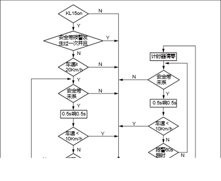
The alarm is triggered by the sound signal, the sound frequency: 2000 ± 10Hz.
Parking brake alarm
Depend on the following signal: parking brake and vehicle speed
Parking brake signal and speed ≥ 5km / h.
Signal output
The alarm is triggered by the sound signal, the sound frequency: 2000 ± 10Hz, vocal cycle: longing.
![]() Button function: 1. Up: Select the previous option of
the list element and press and hold.
Button function: 1. Up: Select the previous option of
the list element and press and hold.
2) Down: Select the next option of the list element to press and hold.
3) Confirm: Press to confirm the selection.
4) Back: Press to return to the previous interface.
5) Turn page: Press to bring up the instrument menu interface (dot screen).
![]() Average fuel consumption
Average fuel consumption
Average fuel consumption is the average fuel consumption displayed in L/100 km after the memory was emptied last time. This information can help you adjust your driving habits to achieve the fuel consumption value you expect. The interface is updated every 5 seconds. If you want to measure the average fuel consumption during a certain driving cycle, reset the travel information in the menu to empty the memory before measurement. Clear records, less than 100m driving shows --- L / 100km; After driving 100m, shows the calculated average fuel consumption.
After each ignition, the average fuel consumption using the value of the last exit; if the instrument is disconnected with the battery, the average fuel consumption will reset to 0.
![]() Range
Range
The range is used to display the mileage with current fuel in the tank. The system calculates the range every second, the interface is updated every 10 seconds.
The range value is calculated based on the current fuel consumption. Therefore, due to the different road conditions and driving conditions, the display of the range will change, which will be different from the actual driving distance. This value is for reference only.
When the fuel sensor is open or short circuit, the interface displays "--- km"; “Range” at least shows 50km.
![]() Short range fuel consumption
Short range fuel consumption
Short range fuel consumption shows the average fuel consumption of the last driving cycle in L / 100 km. Each time when the engine stops for more than 2 hours, the short range fuel consumption will be automatically reset to 0. After clearing records, less than 100m driving shows --- L / 100km; After driving 100m, shows the calculated short range fuel consumption.
![]() Cruise speed
Cruise speed
Cruise speed displays vehicle's current cruise speed set by the driver. The cruise speed can be set by cruise switch. If the cruise function is activated, ---km/h will be displayed on screen.
![]() Tire pressure, tire temperature
Tire pressure, tire temperature
250 250 kPa kPa 44 44 ņ ņ 250 250 kPa kPa 44 44 ņ ņ
Tire
pressure/temperature monitor interface: it can monitor tire pressure and
temperature. The unit of tire pressure is kPa, and the accuracy is 1kPa. When
invalid value is received, the screen will flash in 1Hz, with -.- shown on
screen. The unit of tire temperature is ℃, and the accuracy is 1 ℃. When
invalid value is received, the screen will flash in 1Hz, with - shown on
screen.
|
No. |
Item |
Torque (N·m) |
|
1 |
Instrument cluster screw |
4~6 |
1. Check for after-sale devices that may affect the operation of the instrument system.
2. Inspect easily accessible or visible system components for damage or conditions that could cause failure.
3. Check whether the sensors of different information are normal.
|
No. |
Fault symptoms |
Fault analysis |
Solutions |
Remark |
|
1 |
Instrument cluster malfunction |
The circuit is disconnected |
Check power supply and grounding circuit |
|
|
Damaged instrument circuit |
Replace the instrument cluster |
|||
|
2 |
The light and indicating light are off |
The circuit is disconnected |
Check if the circuit and connection pieces are connected |
|
|
Control signal flow fault |
Check the related switching signal |
|||
|
Damaged instrument circuit |
Replace the instrument cluster |
|||
|
3 |
The indicating instrument has error or fault. The mileage LCD does not work. |
System Malfunction |
Check if all relative sensors have normal output. If all the circuits and connecting pieces are connected. |
|
|
Damaged instrument circuit |
Replace the instrument cluster |
|||
|
4 |
Mileage information is not completely displayed. |
Instrument Circuit Damage |
Replace the instrument cluster |
|
Fault
removed Replace
combination meter Whether
accord with standard value Check the
resistance between terminal 23 of instrument cluster harness connector M36
and body grounding Resistance
standard value: less than 1Ω Check the
power supply voltage of terminal 18 and 19 of instrument cluster wire
harness connector M36 Standard
value: 11 ~ 14V Whether
accord with standard value No No No Yes Yes Yes Repair
the open circuit between the terminal 23 of instrument cluster harness
connector M36 and body ground Check
open circuit fault between terminal 18 and 19 of instrument cluster wire
harness connector M36 and fuse Check if
the fuse is broken Check for
short circuit in fuse circuit or replace fuse Check
instrument cluster fuse FS34, FS22 Fault:
Instrument cluster malfunction
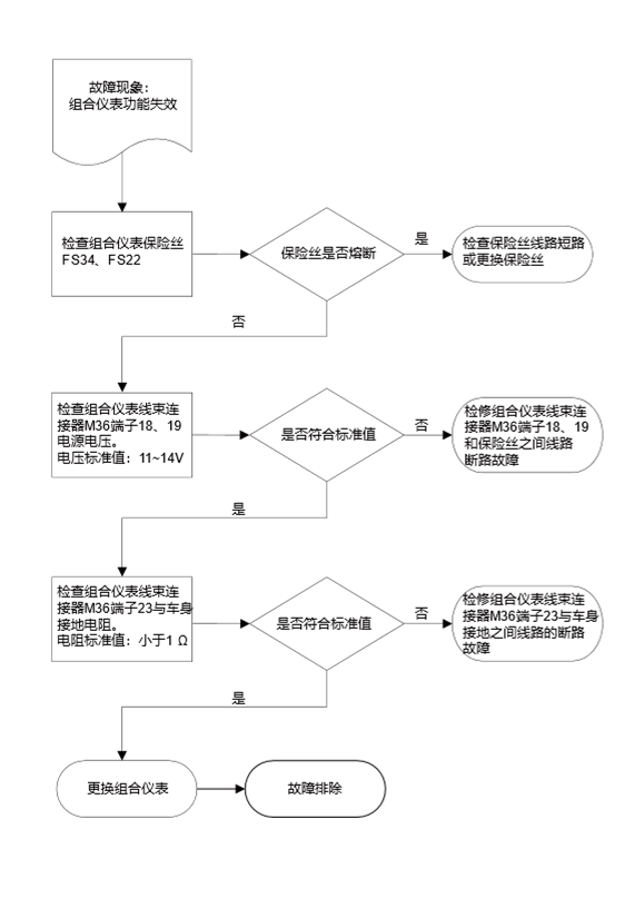
M36
Instrument cluster
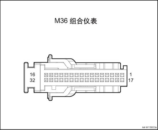
|
Connector serial number |
Connector pin |
Wire Color |
Wire Diameter |
Pin Definition |
|
M36 |
8 |
O |
0.5 |
CAN_H |
|
M36 |
9 |
Y |
0.5 |
CAN low |
|
M36 |
11 |
Y |
0.5 |
Brake fluid level - |
|
M36 |
15 |
G/O |
0.35 |
Rear radar beep signal + |
|
M36 |
18 |
Gr/Y |
0.5 |
B+ Power |
|
M36 |
19 |
O/G |
0.5 |
IGN signal |
|
M36 |
23 |
B |
0.5 |
GND |
|
M36 |
24 |
Bl/Y |
0.5 |
Fuel sensor GND |
|
M36 |
25 |
Bl/G |
0.5 |
Fuel signal |
|
M36 |
29 |
G/B |
0.5 |
Charging indicator - |
|
M36 |
30 |
P/B |
0.5 |
Engine oil pressure - |
|
M36 |
31 |
Bl/Br |
0.35 |
Steering wheel switch signal + |
|
M36 |
32 |
Gr/R |
0.35 |
Steering wheel switch signal - |
1. Open the engine cover
2. Disconnect the battery negative cable.
3. Remove the instrument cluster cover assembly, refer to the instrument cluster cover assembly
4. Disassemble instrument cluster assembly.
![]() 1) Dismantle the 4 screws fixing
the instrument cluster assembly.
1) Dismantle the 4 screws fixing
the instrument cluster assembly.
![]() 2) Disconnect the instrument
cluster assembly wire harness connector.
2) Disconnect the instrument
cluster assembly wire harness connector.
3) Take off the instrument cluster assembly.
1. Install the instrument cluster assembly.
![]() 1) Put the instrument cluster
assembly at installation position.
1) Put the instrument cluster
assembly at installation position.
2) Connect the instrument cluster assembly wire harness connector.
3) Mount and tighten the 4 screws that fix the instrument cluster assembly.
![]() Tightening torque 4~6N·m
Tightening torque 4~6N·m
2. Install instrument cluster cover assembly
3. Connect the battery negative cable.
4. Close the engine compartment cover.
The wiper has four control modes: high speed, low speed, auto, and inching, the wiper switch is integrated on the combination switch on the right of the steering column. The front wiper system consists of wiper/washer switch, wiper motor, connecting rod, wiper arm and wiper blade. There is a self-stop device in the front wiper circuit, which consists of a worm gear and a cam disc. The purpose of the device is to keep the circuit intact for a short time after the wiper / wash switch is off until the wiper arm is fully returned to the initial position The wiper system is driven by a permanent magnet motor, which is mounted on the front wall panel and directly connected to the front wiper rod.
The windshield washer system consists of glass cleaner, washing water pipe, washing kettle & motor assembly, front nozzle, rear nozzle and washing switch. The windshield washing kettle is installed under the right front headlamp assembly. The washing motor is fixed on the washing kettle. and the washing motor rotates forward and reversely so that the glass cleaner is delivered to the front nozzle or the rear nozzle through the hose.
When the ignition switch is "ON”, the wiper switch is set to AUTO, and automatic wiping in rain function on MP5 is turned on, the rain sensor is activated, and the wiper can work intelligently.
![]()
1. Washing kettle & motor assembly
2. Front washing hose
3. Front nozzle
4. Front wiper motor and connecting rod assembly
5. Front wiper arm
6. Front wiper blade
7. Rain sensor
|
No. |
Item |
Torque (N·m) |
|
1 |
Front wiper motor and connecting rod assembly fixing bolt |
10~12 |
|
2 |
Rear wiper arm assembly nut |
17~21 |
|
Common failures |
Failure causes and solutions |
|
|
Stop working |
Moving parts get stuck |
Exclude the stuck |
|
Power off,the connector falls off |
Power on |
|
|
The motor is burned |
Replace a new motor |
|
|
Abnormal noise,Doesn’t work normally |
Abnormal noise inside the motor |
Replace the motor |
|
The connecting mechanism has collision and friction during movement |
Exclude collision and friction |
|
|
Abnormal noise between blade and windshield |
Clean the windshield |
|
|
The wiper blade shakes during work. |
Add cleanser to the washer kettle to reduce friction during work, adjust or replace. |
|
|
Can not wipe clean |
The windshield is not clean |
Clean the windshield |
|
The wiper blade is badly worn |
Replace the wiper blade(it is recommended to change the wiper blade every 3 months) |
|
|
No. |
Measure |
Normal Result |
Abnormal Result |
|
1 |
Turn the ignition switch to “ON”, keep the washer switch to “ON” position |
The wiper works at low speed As long as the washer switch is held in the on position, the washer sprays on the windshield. Turn off the switch, the washer stops working and the wiper returns to the stop position after 2-4 times |
The washer does not work |
|
2 |
Place the wiper switch at interval position |
After the wiper has completed one wipe, it will pause for a few seconds, and then perform the next wipe. |
The wiper delay mode does not work The wiper defog, delay and low speed mode do not work |
|
3 |
Place the wiper switch at interval position, keep wiper switch on for 1-2 s |
As long as the washer switch is held in the on position, the washer sprays on the windshield. The wiper works at low speed during spraying,the blade wipes for 2-4 times after turn off the washer switch Then,the wiper returns to interval work |
The washer does not work, the wiper delay mode does not work The wiper inching, interval and low speed mode do not work |
|
4 |
Turn the wiper switch to low speed position |
The wiper continues to work at low speed |
The wiper inching, interval and low speed mode do not work |
|
5 |
Turn the wiper switch to High speed(HI) position |
The wiper continues to work at high speed |
The wiper can not work at high speed model,it works at low speed model |
|
6 |
Switch the wiper to OFF position. |
The wiper returns to the stop position |
The wiper doesn’t stop |
The wiper and washer don’t work wherever the wiper switch’s position
|
Step |
Solution |
Yes |
No |
|
1 |
Check to see whether the fuses in the fuse box in the engine hood and cab are blown |
Turn to step 2 |
Turn to step 3 |
|
2 |
After excluding failures caused by other wiring problems,replace the fuse to check whether the failure is solved |
|
Turn to step 3 |
|
3 |
Turn on the ignition switch, check whether the motor’s power supply and ground is normal |
|
Turn to step 4 |
|
The voltage between the wiper motor connector terminal 3 and ground is 12V and terminal 1 is grounded |
|||
|
The voltage between pin 4 and ground of the washer motor is 12V |
|||
|
4 |
Replace the wiper and washer motors,check whether the failure is solved |
|
Turn to step 5 |
|
5 |
Replace the wiper switch |
|
|
Wiper does not work at high speed
|
Step |
Solution |
Yes |
No |
|||
|
1 |
Check whether the pin 4 and pin 1 of the wiper motor are connected |
Turn to step 3 |
Turn to step 2 |
|||
|
2 |
Replace the wiper motor |
|
Turn to step 3 |
|||
|
3 |
Check whether the connecting wire between pin 2 of the wiper motor and wiper combination switch is normal |
Turn to step 5 |
Turn to step 4 |
|||
|
4 |
Repair or replace the connecting wire between pin 2 of the wiper motor and wiper combination switch, check whether the failure is solved |
|
Turn to step 5 |
|||
|
5 |
Turn the wiper combination switch to high speed, heck whether the resistance between pin 9 and 8 is normal. / |
Turn to step 7 |
Turn to step 6 |
|||
|
6 |
Replace the switch to check whether the failure is solved |
|
Turn to step 7 |
|||
|
7 |
Repair or replace the connecting wire between pin 6 of wiper switch and ground |
|
|
|
|||
Wiper does not work at low speed only.
|
Step |
Solution |
Yes |
No |
|
1 |
Check whether the pin 3 and pin 1 of the wiper motor are connected |
Turn to step 3 |
Turn to step 2 |
|
2 |
Replace the wiper motor |
|
Turn to step 3 |
|
3 |
Check whether the connecting wire between pin 3 of the wiper motor and wiper combination switch is normal |
Turn to step 5 |
Turn to step 4 |
|
4 |
Repair or replace the connecting wire between pin 3 of the wiper motor and wiper combination switch,Check whether the failure is solved |
|
Turn to step 5 |
|
5 |
Turn the wiper combination switch to low speed, heck whether the resistance between pin 9 and 8 is normal. |
Turn to step 7 |
Turn to step 6 |
|
6 |
Replace the switch to check whether the failure is solved |
|
Turn to step 7 |
|
7 |
Repair or replace the connecting wire between pin 6 of wiper switch and ground |
|
|
The wiper does not work at interval position only.
|
Step |
Solution |
Yes |
No |
|
1 |
Turn the wiper combination switch to interval position, check whether the resistance between pin 9 and 8 is normal. |
Turn to step 3 |
Turn to step 2 |
|
2 |
Replace the switch to check whether the failure is solved |
|
Turn to step 3 |
|
3 |
Check whether the connecting wire between pin 8 of the wiper motor and BCM |
Turn to step 5 |
Turn to step 4 |
|
4 |
Repair or replace the connecting wire between wiper combination switch pin 8 and BCM, check whether the failure is solved |
|
Turn to step 5 |
|
5 |
Check whether the wiring between BCM and wiper relay terminal is conducted. |
Turn to step 7 |
Turn to step 6 |
|
6 |
Repair or replace the connecting wire between BCM and wiper relay terminal, check whether the failure is solved. |
|
Turn to step 7 |
|
7 |
Turn the ignition switch to ON position,turn the wiper switch to interval mode,check whether the wiper relay is connected to ground |
Turn to step 9 |
Turn to step 8 |
|
8 |
Replace the BCM Whether the failure is solved |
|
Turn to step 9 |
|
9 |
Replace wiper relay |
|
|
|
Step |
Solution |
Yes |
No |
|
1 |
Check whether the continuity of the wiper combination switch in each gear is normal |
Turn to step 3 |
Turn to step 2 |
|
2 |
Replace the wiper combination switch Whether the failure is solved |
|
Turn to step 3 |
|
3 |
Check whether the connecting circuit between the wiper combination switch and the wiper motor is normal |
Turn to step 5 |
Turn to step 4 |
|
4 |
Repair or replace the connecting circuit between the wiper combination switch and the wiper motor, and check whether the fault is eliminated |
|
Turn to step 5 |
|
5 |
Replace the wiper motor |
|
|
|
Step |
Solution |
Yes |
No |
|
1 |
Check whether the power supply of the washer motor is normal, turn on the ignition switch,the voltage between the positive port of the washer motor plug and ground should be equal to the battery voltage |
Turn to step 3 |
Turn to step 2 |
|
2 |
Repair or replace the power supply wiring of the washer motor,whether the failure is solved |
|
Turn to step 3 |
|
3 |
Check whether the output voltage of the BCM terminal 10 is normal |
Turn to step 5 |
Turn to step 4 |
|
4 |
Repair or replace BCM |
|
Turn to step 5 |
|
5 |
Replacing the washing motor |
|
|
Ⅲ Front Wiper Motor & Connecting Rod Assy.
1. Open the engine cover
2. Disconnect the battery negative cable.
3. Disassemble front wiper arm assembly. See the “front wiper arm assembly”.
4. Remove the vent cover assembly. See the “vent cover assembly”
5. Dismantle the front wiper& connecting rod assembly.
1) disconnect the front wiper& connecting rod assembly WIR harness connector 1.
2) Dismantle the 3 bolts fixing the front wiper& connecting rod assembly.
![]() 3) Remove the front wiper&
connecting rod assembly.
3) Remove the front wiper&
connecting rod assembly.
△Attention Before removing the wiper motor and connecting rod assembly, make sure that the connecting rod stops at the automatic stop position. During the disassembly, do not move the wiper blade violently or it will damage the blade and affect the effect of wiper
1. Disconnect the wiper motor wire harness connector.
Terminal 2,3,4 are connected to the positive terminal of the battery, terminal 1 is connected to the negative terminal of the battery
|
NO. |
1 |
2 |
3 |
|
|
Definition |
GND |
Stopping position |
Low speed |
High speed |
![]() 3. As shown in the table, check
whether the motor is normal
3. As shown in the table, check
whether the motor is normal
/ 1 2 3 4 OFF L0 HI
△ attention: In
general, contamination come from insects, sap, and hot wax treatment. If the
wiper blade can not work normally,use good or mild cleaner to clean the
windshield and blade,and then clean with clean water thoroughly
1. Install the the front wiper& connecting rod assembly.
1) Put the the front wiper& connecting rod assembly at installation position.
2) Mount and tighten the 3 bolts fixing the front wiper& connecting rod assembly.
Tightening torque 10~12N·m
![]() 3) Connect the front wiper&
connecting rod assembly WIR harness connector 1.
3) Connect the front wiper&
connecting rod assembly WIR harness connector 1.
2. Install the vent cover assembly
3. Install front wiper arm assembly
4). Connect the battery negative cable.
5. Close the engine compartment cover
1. In 30s after turning the ignition switch to "OFF” , turn the wiper switch to inching mode for more than 2s, and the wiper moves to the maintenance position.
![]() 2. Disassemble the front wiper arm
assembly
2. Disassemble the front wiper arm
assembly
1) Remove the front wiper end cap.
2) Remove the two nuts securing the front wiper arm.
3) Remove front wiper arm.
![]() 4) separate the front wiper blade
4) separate the front wiper blade
1. Install front wiper arm assembly
![]() 1) install the front wiper blade on
the front wiper arm.
1) install the front wiper blade on
the front wiper arm.
![]() 2) Mount the two nuts securing the
front wiper arm.
2) Mount the two nuts securing the
front wiper arm.
Tightening torque 17~21N·m 3) Install the end cap.
2. Reset the wipe blade.
1. Disassemble the front wiper blade assembly
![]() 1) In 30s after turning the
ignition switch to "OFF” , turn the wiper switch to inching mode for more
than 2s, and the wiper moves to the maintenance position.
1) In 30s after turning the
ignition switch to "OFF” , turn the wiper switch to inching mode for more
than 2s, and the wiper moves to the maintenance position.
2) Pull up the wiper arm
3) Press the connection with a thumb and pull out the wiper blade.
1. Install the front wiper blade assembly
![]() 1) Insert the wiper blade into the
wiper arm slot
1) Insert the wiper blade into the
wiper arm slot
2) Place down the wiper arm.
3) Reset the wipe blade.
1. Open the engine cover
2. Disconnect the battery negative cable.
3. Remove front bumper body assembly. See front bumper assembly
4. Discharge washing liquid.
5. Dismantle the washing liquid kettle & motor assembly.
1) Disconnect the the washing liquid kettle & motor assembly wire harness connector 1.
2) Disconnect the motor and washing liquid pipe 2.
3) Dismantle the 3 bolts 3 fixing the washing liquid kettle & motor assembly.
![]() 4) Take down the washing liquid
kettle & motor assembly.
4) Take down the washing liquid
kettle & motor assembly.
1. Install the washing liquid kettle & motor assembly
1) Put the washing liquid kettle & motor assembly at the installation position
![]() 2) Install the 3 bolts 3 that fix the washing liquid
kettle & motor assembly.
2) Install the 3 bolts 3 that fix the washing liquid
kettle & motor assembly.
Tightening torque 6 ~ 9N·m
3) Connecting the washing liquid pipe 2 to the motor.
4) Connect the the washing liquid kettle & motor assembly wire harness connector 1.
2. Install front bumper assembly
3. Fill washing liquid.
4). Connect the battery negative cable.
5. Close the engine compartment cover
△Attention: Before adding washing liquid, check the kettle to see if there is any foreign matter or pollution. Clean the washing liquid kettle if necessary.
1. Open the engine cover
2. Remove the vent cover assembly. See the “vent cover assembly”
3. Remove front nozzle.
1) Disconnect the front window nozzle and front washing liquid pipe connection.
![]() 2) Pry off the front window nozzle.
2) Pry off the front window nozzle.
![]() 1. Install front window nozzle
1. Install front window nozzle
1) Install the front window nozzle to the vent cover assembly.
2) Connect the front window nozzle and front washing liquid pipe.
△Attention: adjust the front nozzle to proper position after installation.
2. Install the vent cover assembly
3. Close the engine compartment cover
1. Open the engine cover
2. Disconnect the battery negative cable.
3. Remove front bumper body assembly. See front bumper assembly
4. Remove the vent cover assembly. See the “vent cover assembly”
5. Remove the front washing liquid pipe assembly
![]() 1) Disconnect the front washing
liquid pipe assembly and washer motor.
1) Disconnect the front washing
liquid pipe assembly and washer motor.
2) Disconnect the front washing liquid pipe assembly from front window nozzle.
![]()
![]() 3) Detach the front washing liquid
pipe assembly from the body buckles.
3) Detach the front washing liquid
pipe assembly from the body buckles.
4) Pull out the front washing liquid pipe assembly.
1. Install the front washing liquid pipe assembly.
1) Install the front washing liquid pipe assembly into the mounting position.
![]()
2) Install the front washing liquid pipe assembly fixing buckles.
![]() 3) Connect the front washing liquid
pipe assembly with front window nozzle.
3) Connect the front washing liquid
pipe assembly with front window nozzle.
![]() 4) Connect the front washing liquid
pipe assembly and washer motor.
4) Connect the front washing liquid
pipe assembly and washer motor.
Install wheel fender
3. Install the vent cover assembly
4. Install front bumper assembly
5). Connect the battery negative cable.
6. Close engine compartment cover
1. Open the engine cover
2. Disconnect the battery negative cable.
3. Remove front bumper body assembly. See front bumper assembly
4. Dismantle the washer motor.
![]() 1) Disconnect the the washer motor
assembly wire harness connector 1.
1) Disconnect the the washer motor
assembly wire harness connector 1.
2) Disconnect the motor and washing liquid pipe 2.
3) Remove the washer motor.
1 Install the washer motor.
![]() 1) Put the washer motor at the
installation position
1) Put the washer motor at the
installation position
2) Connecting the washing liquid pipe 2 to the motor.
3) Connect the the washer motor assembly wire harness connector 1.
2. Install front bumper assembly
3. Connect the battery negative cable.
4. Close the engine compartment cover.
△Attention: Before adding washing liquid, check the kettle to see if there is any foreign matter or pollution. Clean the washing liquid kettle if necessary.
1. Open the engine cover
2. Disconnect the battery negative cable.
3. Dismantle the rain sensor.
![]() 1) Remove the rain sensor cover
1) Remove the rain sensor cover
2) Disconnect the rain sensor wire harness connector 1.
3) Dismantle the metal snap ring 2.
4) Take off the rain sensor.
1. Install the rain sensor
![]() 1) Put the rain sensor at
installation position.
1) Put the rain sensor at
installation position.
2) Clip the rain sensor on the snap ring 2.
3) Connect the rain sensor wire harness connector 1.
4) Install the rain sensor cover
△Attention: When installing the rain sensor, do not touch the soft silica gel on the surface of the sensor. After installation, make sure that there are no air bubbles between the sensor and the glass in the installation area. If there are bubbles, remove the sensor and re install it.
2). Connect the battery negative cable.
3. Close the engine compartment cover
The rear view mirror include an inner rearview mirror and two outer rearview mirrors. They are fixed on the top of the front windshield and the left and right side out of the vehicle body respectively for observing the cabin and the back of the vehicle. The rear-view mirror control system consists of exterior mirrors, folding switch, rearview mirror control module assembly. Outer mirrors are controlled by the electric mirror switch panel on the left side of the dashboard.
Outer mirrors are controlled by the electric mirror switch panel on the left side of the dashboard.
Components Layout
![]()
1. Interior rearview mirror
2. Left outer rearview mirror
3. Right outer rearview mirror
|
No. |
Item |
Torque (N·m) |
|
1 |
Outer rearview mirror assembly fixing bolts |
7~9 |
|
2 |
Inner rearview mirror assembly fixing bolts |
1.1~1.9 |
|
Serial No. |
Fault symptoms |
Fault analysis |
Solutions |
Remark |
|
1 |
Power rear view mirror can not adjust |
Fuse failure |
Check and repair the wiring short circuit fault or replace the fuse. |
Refer to power rearview mirror can not adjust |
|
2 |
Adjust the motor fault |
Change and adjust the motor |
||
|
3 |
Adjust the switch malfunction |
Change the adjustment switch |
||
|
4 |
Poor contact of wire harness and connector |
Check and repair the wire harness and connector |
||
|
5 |
Poor contact of relative grounding point |
Check and repair the grounding point circuit |
||
|
6 |
Related power supply wire harness fault |
Check and repair the power supply circuit |
||
|
7 |
BCM damaged |
Replace the BCM |
Power rearview mirror can not adjust
Fault
cleared. Replace
power rearview mirror motor. Check the
resistance between terminal 2, 3 and 4 of power rearview mirror motor
harness connector D07 and the switch terminal Resistance
standard value: less than 1Ω Whether
accord with standard value Whether
accord with standard value Operate
the power rearview mirror switch, check the internal continuity of the
power rearview mirror switch, and measure the resistance value Resistance
standard value: less than 1Ω Check and
repair the circuit Whether
accord with standard value Check the
power supply voltage and grounding resistance of the power rearview mirror
switch Standard
value: 11 ~ 14V Resistance
standard value: less than 1Ω Check
that if the fuse is blown. No No No Yes Yes Yes Yes Yes Replace
power rearview mirror switch Repair
the open circuit fault between terminal 2, 3 and 4 of power rearview mirror
motor harness connector D07 and the switch terminal Check for
short circuit in fuse circuit and replace fuse Check if
the indoor fuse is blown Power
rearview mirror can not adjust
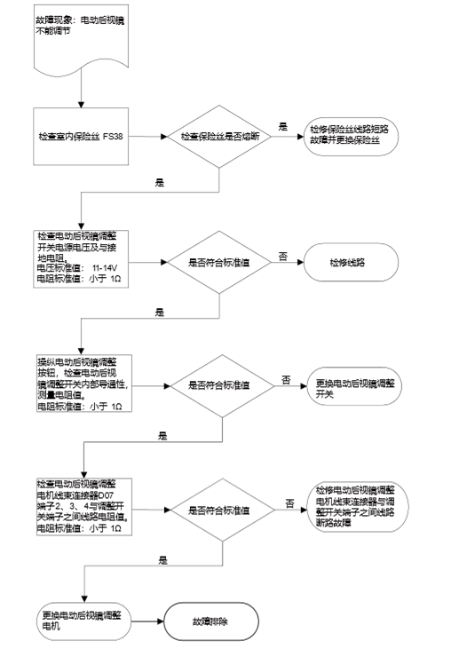
Ⅲ Outer Rearview Mirror Assembly
△Note: Left and right outer rearview mirror disassembly method is similar.
1. Open the engine cover
2. Disconnect the battery negative cable.
3. Remove the front door assembly. See the “front door panel assembly”.
4. Dismantle the outer rearview mirror assembly.
![]() 1) Disconnect the outer rearview
mirror switch wire harness connector.
1) Disconnect the outer rearview
mirror switch wire harness connector.
2) Remove the 3 nuts2 that fix the outer rearview mirror assembly.
3) Remove the outer rearview mirror assembly.
1. Install the outer rearview mirror assembly
![]() 1) Put the outer rearview mirror assembly at
installation position.
1) Put the outer rearview mirror assembly at
installation position.
2) Mount the 3 nuts2 that fix the outer rearview mirror assembly.
Tightening torque 7 ~ 9N·m
3) Connect the outer rearview mirror switch wire harness connector 1.
△Note: When installing the rearview mirror, first cross rearview mirror assembly connector through the door, place the liner near the vehicle door junction
△ Note: Connect the rearview mirror assembly connector to the vehicle wiring socket.
△ Note: There is liner connection between rearview mirror assembly and vehicle door, it has the function of shock absorption and sealing.
2. Install the front door panel assembly
3. Connect the battery negative cable.
4. Close the engine compartment cover.
![]() 1. Remove the inner rearview mirror assembly.
1. Remove the inner rearview mirror assembly.
1) Remove the 1 screw that fix the inner rearview mirror assembly.
2) Take down the inner rearview mirror assembly.
1. Install the inner rearview mirror assembly.
![]() 1) Put the inner rearview mirror
assembly at installation position.
1) Put the inner rearview mirror
assembly at installation position.
2) Mount the 1 screw that fix the outer rearview mirror assembly.
Tightening torque 1.1~1.9N·m
Tire Pressure Monitoring System
![]()
1. Tire pressure monitoring sensor
Tire pressure monitoring system can monitor the pressure and temperature in the tire, give alarm in time when the setting value is exceeded (the alarm is indicated by the instrument light), help the driver to grasp the condition of the tire in real time and reduce the traffic accidents caused by the tire failure, increasing vehicle driving safety.
![]() TPMS system consists of three
components: warning indicator (integrated on the instrument), MP5 display, tire
pressure monitoring controller(integrated in the BCM), tire pressure monitoring
sensor. Detailed components are as follows:
TPMS system consists of three
components: warning indicator (integrated on the instrument), MP5 display, tire
pressure monitoring controller(integrated in the BCM), tire pressure monitoring
sensor. Detailed components are as follows:
|
Part Name |
Quantity |
Remark |
|
Tire pressure monitoring controller |
4 |
Installed in four tires |
|
alarm indicator |
2 |
Integrated on the instrument cluster (two indicators): 1. Warning indicator 2. |
|
MP5 display |
1 |
Display on the MP5 |
Tire pressure monitoring instructions
|
Symbol (instrument) |
Indicator lamp type |
Indicator type |
|
|
Abnormal Tire Pressure |
Rapid Leakage: Flashing Low Pressure: Steady High Pressure: Steady High Temperature: Steady |
|
TPMS |
System fault |
Sensor
battery low power: indicator always on |
Alarm type and description
|
Alarm type |
Description |
|
Rapid tire leakage |
When the system is running, one or more tire pressure drops more than 30kPa within 1 minute and a rapid leak alarm is issued; if the pressure does not change or rises, the rapid leak alarm is released. |
|
Low pressure |
When the system is running, one or more tire pressures are lower than 75% of the cold pressure value specified by the manufacturer, the low pressure alarm is issued; the pressure returns to normal and the low pressure alarm is released. |
|
High pressure |
When the system is running, one or more tire pressures are higher than 125% of the cold pressure value specified by the manufacturer, and a high pressure alarm is issued; the pressure returns to normal and the low pressure alarm is released. |
|
High temperature |
When the system is running, one or more tires are above 85 ℃, and a high temperature alarm is issued; the temperature returns to normal and the high temperature alarm is released. |
|
Sensor battery low power |
When the system is running, one or more of the tire pressure sensor battery power is lower than a certain value, and a low battery alarm is issued; the battery returns to normal, and the low battery alarm is released. |
|
Sensor failure |
When the system is running, vehicle speed is more than 25km/h, one or two sensor valid data is not received within 58 minutes (the rest of the sensors can receive valid data), and a sensor failure alarm is issued; all sensor valid data are received and the failure alarm is released. |
![]() ① Ignition switch ON/START, if the
four sensors have been bound, the indicator light and the TPMS system fault
light turn on 2s and turn off at the same time.
① Ignition switch ON/START, if the
four sensors have been bound, the indicator light and the TPMS system fault
light turn on 2s and turn off at the same time.
![]() ② Ignition switch ON/START. If four
sensors are bound, the tire pressure warning indicator will turn off after 2s.
TPMS system failure lamp will twinkle in the period of 2s.
② Ignition switch ON/START. If four
sensors are bound, the tire pressure warning indicator will turn off after 2s.
TPMS system failure lamp will twinkle in the period of 2s.
③Enter the sensor learning mode, the two lights turn on at the same time (light), when the binding is successful, the two lights turn off at the same time.
④ driving process, the system and the pressure is normal, the two lights do not light.
⑤ release the alarm, the corresponding alarm light goes out.
⑥ System according to the priority of the alarm is divided into three levels (the highest level is first level): First level: rapid leak
Level
2: low pressure, high pressure, high temperature
Level 3: sensor battery low power, sensor failure, high frequency reception
failure
When an alarm status is indicated, the high-level alarm indicator lights first, and both LEDs do not light at the same time.
⑦ After low pressure, high pressure, missing alarm sensor (corresponding indicator light), if the ignition switch is turned OFF to ON, the system will keep the last time driving alarm status indicator, pressure and temperature data, after troubleshooting, you need to drive for 3 minutes to make sensor get into working state to send pressure and temperature data, tire pressure controller will update the status to make alarm automatically eliminate; In case of system failure or failure to learning (corresponding indicator light is on), if the ignition switch is switched OFF and switched ON again, the system will retain the status indication and pressure and temperature data of the previous driving alarm. After troubleshooting, the alarm will be automatically removed after power on again;
Description:
433.92MHz RF Signal Instrument
cluster, MP5 Tire
pressure monitoring controller Sensor Sensor Sensor Sensor
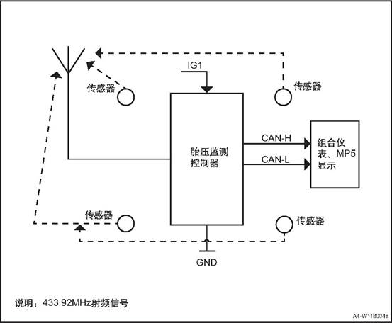
|
No. |
Item |
Torque (N·m) |
|
1 |
Tire pressure monitoring controller fixing bolt |
8~10 |
The TPMS system is the tire pressure monitoring auxiliary system. The signal transmission is completed by the high-frequency signal. When the high-frequency signal is interfered by the same frequency electromagnetic field and interfered with for a long time, it will send a system fault alarm. When the car is away from the strong magnetic field, alarm status will be automatically lifted, it is normal
Driving on a bumpy road, the vehicle turns, and the tires are stressed differently. As a result, the tire pressure is too high or too low during this period. Sometimes the system may occasionally get an alarm and travels to a flat and straight road. If the pressure is normal, it will be automatically released alarm, it is normal.
There is no tire pressure monitoring sensor installed in the spare tire. After changing the spare tire, the TPMS system fault light will be on constantly. You need to learn again to clear the failure indicating lamp.
1. Due to the consideration of energy-saving of the sensor, the sensor will enter the positioning mode only when the vehicle stops for more than 10 minutes and the vehicle speed is greater than or equal to 30km / h;
2. When the sensor is in the positioning mode, in addition to the normal tire pressure information message, the sensor will send the positioning message for 6 minutes in total. If the vehicle speed drops to 30km / h, stop sending positioning message, and resume sending when the speed rises to 30km / h;
In order to match the positioning mode of the sensor, the BCM will only start the automatic positioning software when ignition switch is turned to ON after 15min in OFF state and the vehicle speed is more than 20km / h and the vehicle speed is more than 20km / h. The software will stop waiting when the vehicle speed is less than 10km / h.
Four-wheel tooth number pulse signal is indispensable. If a wheel speed sensor of ABS / ESP fails to output the correct signal, the ABS fault light on the instrument panel will be on. At this time, the fault cannot be located, and the fault must be repaired first;
After BCM detects the reverse signal, it will discard the data collected before and collect the data again for calculation. Due to the limited time of monitoring message sent by the sensor, the monitoring may fail due to insufficient data.
When the vehicle stops and remains under OFF power for more than 15min, and then it ignites again and drive, when the vehicle speed exceeds 30km/h, BCM will automatically start the automatic monitoring program. Because the starting and operating conditions of the automatic positioning function are relatively simple, the tire pressure sensor can be calibrated and matched in daily use to ensure that the tire pressure system operates in the correct state.
/
Under normal circumstance, the vehicle speed > 30km/h is kept for 2~6 minutes, it can be positioned successfully, the tire pressure and temperature data on the instrument/MP5 interface will be updated with the status of the vehicle display.
Since the learning function has certain requirements on the operation process, in order to ensure the success of one-time positioning learning after adjusting the tire sequence or replacing the tire pressure monitoring sensor, the following matters should be paid attention to:
1. Make sure that no ABS fault light is on;
2. Choose a route with good road condition in advance to avoid the vehicle speed running within 20km/h for a long time due to traffic jam;
3. The vehicle battery power OFF, or in OFF power to maintain more than 18 minutes, and then ignition start;
4. When the vehicle drives out of the parking space and the speed exceeds 30km / h and the automatic positioning is started, do not shift into the reverse gear within 15min (the automatic transmission model shall keep the D gear), otherwise, it may be necessary to re-locate the vehicle;
5. In case of temporary stop such as red light on the road, the positioning calculation will not be affected, but the corresponding calculation time will be extended.
(1) Before adjusting the tire order, enter the function page of "JAC diagnostic APP" -- "auto diagnosis" -- "Refine R3" -- then enter the sub-function of "body controller (BCM)" -- "real-time data" to read the tire pressure sensor ID and record the sensor ID of the 4 wheels.
(2) Return to "body controller (BCM)", then enter the "data write" sub-function, according to the need to adjust the order, use the "sensor ID write" function to re-write the new ID order, and then adjust the tire order.
(1) Before installing the new sensor, check the permanent mark on the sensor surface, record the sensor ID (as shown in the figure).
![]()
(2) Get into corresponding vehicle type “BCM”, get into “write data” function, according to the tire position of the replaced sensor, write into the sensor ID.
△Attention: In the case of already written sensor ID, if the write the repeated ID, BCM will refuse to write, APP prompt response timeout.
![]()
![]()
|
Indicator status |
Possible Reasons |
Method of Disposal |
|
Ignition switch ON / START |
The original receiver of the vehicle has not been learned and bound. |
Ask professionals to do hand-held learning in 4S stores |
|
the tire pressure warning indicator point and TPMS indicator light turn on 2s and then go out |
The acceptance controller has been replaced and the receiving controller has not been learned to bind. |
Retrieve all tire sensor IDS |
|
|
Bind all receiver controllers. |
|
|
Indicator lamp flashes |
In the process of driving, if the tire is damaged by puncturing and splitting, and the tire pressure drops rapidly. |
It is necessary to stop as soon as possible and check all tires and air pressure. |
|
While parking (ignition switch ON/START), deflate the tire. |
The alarm will be automatically released after the deflation stops or inflates |
|
|
Indicator always on |
While parking (ignition switch ON/START), deflate the tire, resulting in low pressure. |
Inflate the tire to the correct pressure value. (Marked on the tire label) |
|
During parking (ignition switch ON/START), the tire is inflated and the pressure is too high. |
Deflate the tire to the correct pressure value. |
|
|
When driving on bumpy roads / turning, the stress on each tire is different, resulting in high or low tire pressure during this period |
Drive to a flat/straight road surface and if the pressure is normal, the alarm will be automatically canceled. |
|
|
During driving, the tire pressure was detected to be insufficient (the tire has not been inflated for a long time / leaked due to tire damage). |
It is necessary to stop as soon as possible and check all tires and air pressure. |
|
|
Driving at high speed and overload, causing tires to overheat. |
Slow down and do not overload. |
|
|
During running, the air pressure is insufficient and the friction increases, causing the tire to overheat, causing the tire to overheat. |
It is necessary to stop as soon as possible and check all tires and air pressure. |
|
|
TPMS indicator always on |
One or more tire pressure sensors battery power lower than a certain value. |
Replace sensors at the 4S shop in time and relearn and bind |
|
One or two of the four tires does not have a tire pressure sensor installed. |
Install the correct sensor in the 4S shop and relearn and bind |
|
|
One or two of the four tires are mounted incorrectly (ie, the sensor ID does not match the receiving controller ID). |
Install the correct tire in the 4S shop and relearn and bind. |
|
|
One or two TPMS sensors of the four tires fail, can not transmit data |
Change the sensor in the 4S store and relearn and bind. |
|
|
The high frequency receiving module of the receiving controller is damaged, no data is received for 20 minutes |
Check the receiving controller at the 4S shop. If the receiving controller needs to be replaced, re-learn and bind. |
|
|
The sensor IDs of all four tires and the receiving controller ID do not match and no valid sensor data was received for 20 consecutive minutes. |
Relearn and bind at the 4S shop. |
|
|
Driving in the same-frequency interference area (strong interference, continuous), such as airports, radio towers, etc., may cover the sensor signal. |
After leaving the same frequency interference zone, the alarm status is automatically released. |
|
|
Receiver controller wire harness bad contact |
Unplug the receiving controller and reconnect it |
|
|
The ignition switch is turned from OFF to START or ON,and the indicator does not light. |
Indicator light failure |
To the 4S shop, ask a professional to check the meter. If the meter is damaged, the meter needs to be replaced. |
Ⅳ Tire Pressure Monitoring Sensor
1. Disconnect the battery negative cable.
2. Remove the tire assembly
![]() 3. Dismantle the tire pressure monitoring sensor
3. Dismantle the tire pressure monitoring sensor
1). Remove the tire and remove the tire pressure monitoring sensor fixing nut from the outside of the rim.
2). Remove the tire pressure monitoring sensor from the inside of the rim.
![]()
1. Install tire pressure monitoring sensor
![]() 1) Install tire pressure monitoring
sensor from the inside of the rim.
1) Install tire pressure monitoring
sensor from the inside of the rim.
2) Install the tire and tighten the tire pressure monitoring sensor fixing nut from the outside of the rim.
![]() △Attention: The sealing rubber of
the sensor is tightly fitted with the rim to ensure the tightness of the tire.
△Attention: The sealing rubber of
the sensor is tightly fitted with the rim to ensure the tightness of the tire.
2. Check and calibrate the balancing of the tire, refer to the “wheel balance”.
3. Install the tire assembly
4). Connect the battery negative cable.
5. Adjust the tire pressure of the tire
6. Re-learn and bind the tire pressure monitoring sensor.

