Overall
Description
I.
warning and precautions
(1)
warning and precautions
Definition of "Warning",
"Important Note" and "Attention”
The
diagnostic and maintenance procedures in this manual include general and
specific "warnings", "important notices" and
"cautions", and JAC is committed to providing maintenance information
to assist the after-sales service technician in the diagnosis and maintenance
system , so that the vehicle can run normally, but if the technician does not
operate as recommended, some programs may pose a risk to the technician.
"WARNING",
"IMPORTANT NOTES" and "CAUTION" are prepared to prevent the
occurrence of such hazards, but not all hazards are predictable. This
information is displayed in prominent positions in the maintenance manual. This
information is prepared to prevent the following:
·Causing
serious injury to people
·Vehicle
damage
·Unnecessary
vehicle maintenance
·Unnecessary
parts replacement
Improper
repair or replacement of vehicle parts
The definition of
"Warning"
When
you encounter a "warning", it asks you to take the necessary action
or to prohibit the action taken. If you ignore "warning", you may have
the following consequences:
·Causing
serious injury to people
If
the vehicle is improperly repaired, it will cause serious personal injury to
the driver and / or passenger of the vehicle.
The definition of
"important note"
"Important
note" requires special attention to the measures necessary or prohibited.
If you ignore the "important note", it will lead to the following
consequences:
·Vehicle
damage
·Unnecessary
vehicle maintenance
·Unnecessary
parts replacement
·Abnormal
operation or performance of the system or component being repaired
·Damage
related systems or components
·Damage
fasteners, basic tools or special tools
·Engine
coolant, lubricating oil or other essential liquid leakage
The definition of
"Attention”
The
"attention" statement emphasizes the necessity of a diagnostic or
maintenance procedure, and the purpose of the "attention" statement
is as follows:
Clear
procedure
Provide
supplementary information for completing a program
Clarify
the reason for an operation according to the recommended procedure
Provide
information that helps to complete the program in a more efficient way
Provide
the technician with past experience information to make the process easier
Warning about vehicle lift
△Warning To avoid vehicle damage,
serious personal injury or even death, when the main part is removed from the
vehicle and the vehicle is supported by an elevator, please use jack to support
the corresponding vehicle parts to be dismantled..
Warning about crash repair permission devices
△ Warning To avoid personal
injury when exposed to toxic flamings generated from wipes or electroplating
(zinc oxide) metal during grinding / cutting of any type of metal or sheet
molding, the working process must be operated in a well-ventilated area and
technician should equip permitted respirators, goggles, earplugs, welders
gloves and protective clothing.
Warning about helper driving
△
Warning When the technician checks the defective parts, the vehicle should be
driven by the assistant. Otherwise, it may cause personal injury.
Warning about disconnecting the battery
△
WARNING Before servicing any electrical parts, the ignition key must be in the
OFF or LOCK position and all electrical loads must be "OFF"
),
Unless otherwise stated in the operating procedure. If the tool or equipment is
easily accessible to the exposed live electrical terminals, disconnect the
battery negative cable. Violation of these safety instructions may result in
personal injury and / or damage to vehicles, vehicle parts.
△
Warning If you repair the airbag, you must disconnect the battery negative at least
90s in order to carry out other operations.
Warnings
of inhaling R134a
△Warning Please Avoid absorbing
A/C refrigerant ,134a(R134a),Lubricating oil steam or fog otherwise it will
stimulate the eyes, nose, and pharynx. Please carry out operations in area with
proper ventilation. When exhausting R134a from A/C system, please use service
facilities that meet the standard of SAEJ2210 If unexpected fluid leak happens,
please ventilate workplace before continuing repair. For other information
concerning health and safety, please consult manufacturer of refrigerant and
lubricating oil for details.
Warning
about collision cut
△
Warning please cut the recommended parts only, otherwise it will damage the
integrity of the vehicle structure, and may cause personal injury in the event
of vehicle collision.
Warnings
of cracks on windows
△ Warning If crack appears on the
window, yet the window is intact, please use protective glue tape and stamp the
tape on the window in crossing type, so as to avoid further damage or personal
injury.
Warnings
of windows’ lifting
△Warning When the driver handle
the power window, the function of lifting the window fast may Cause personal
injury
Warning
about eye protection
△WARNING
In the course of this procedure, licensed goggles and gloves should be worn to
reduce the risk of personal injury.
Warnings
of noise-insulating foam material
△ Warning If fire is needed during
repair process, the noise-insulating foam material with a distance of 152.4mm
within the fire must be cleared. When re-installing foam material, please avoid
inhaling smog, or your health will be affected.
Warnings
of glass and metal sheet
△
Warning In the course of processing glass or metal sheet with sharp or rough
edge, licensed goggles and gloves should be equipped to reduce the risk of
personal injury.
Warning
of halogen bulb
△
Warning high-pressure gas exist inside the bulb. Improper operation may cause
bulb’s explosion. To avoid personal injury:
Turn
off light switch and cool down the bulb before replacing bulb
Keep
the light switch shut down until the bulb has been replaced
Please
equip goggles while replacing halogen bulb
While
handling bulb, please hold the base part only and avoid contact with glass
The
bulb should be kept away from dust and moisture
Please
scrap the aged bulb in correct procedures
The
halogen bulb should be kept away from children
Warning
about moving parts and hot surfaces
△
WARNING When working around the running engine, avoid contact with moving parts
and hot surfaces to prevent personal injury.
Warning
about goggles and gloves
△ WARNING Do not wear goggles and
gloves when removing exhaust system parts, otherwise rusting and sharp edges
from worn parts of the exhaust system can cause serious personal injury.
Warning
about removal of tank cover
△ WARNING To avoid being burned, do
not remove the tank cover until the engine is cooled. If the tank and the
radiator are not cooled, remove the tank cover, the cooling system will release
hot high pressure liquid and steam.
Warning
about road test
△WARNING Please test vehicle with
your safety guaranteed and follow traffic regulations. Do not attempt any
operation that may endanger vehicle control. Violation of these safety
instructions may result in serious personal injury and vehicle damage.
Warning
about goggles and fuel
△
Warning When processing fuel, be sure to equip goggles to prevent oil from
splashing into the eyes.
Airbag
system
△
Warning Airbag system has been equipped on this vehicle. Failure to carry out
correct operation procedures may cause following situations:
Unexpected
airbag explosion
Pre-tightener
spark-off
Person
injury
Unnecessary
repair of airbag system
△
Warning please obey the following instructions to avoid the situations
mentioned above:
Please
refer to the overview of airbag system, and confirm whether repairing
operations are carried out on airbag system’s parts and circuits.
Please
secure the airbag system if you are carrying out repair on airbag system’s
parts and circuits.
Warnings of the high-temperature on released airbag
module
△
Warning when the airbag is released, the metal surface of airbag system module
will be very hot. To avoid fire accident and personal injury:
Make
sure the metal surface is fully cooled down for a certain time before touching
Do
not put the released airbag system module near any inflammable objects.
Warnings
on the clock spring of airbag system
△ Warning incorrect assembly of
clock spring may cause damage to the inner spiral coil, which will cause
failure of coil and airbag module, and lead to potential personal injury.
Warnings
of airbag module’s scrapping
△
Warning to avoid unexpected release of airbag and personal injury, do not
operate the unreleased airbag module as scrapped objects in workplace. If the
sealing container is damaged during scrapping process, some materials in the
unreleased module may cause illness or personal injury. Please scrap the
unreleased airbag module by following releasing procedures.
Warnings
of airbag module’s handling and storing
△
Warning while transporting unreleased airbag module:
Do
not lift the wire or connector on airbag module
Ensure
the airbag’s opening hasn't been put toward you or other people.
△ Warning while storing unreleased
airbag module, ensure the airbag's opening is not facing the surface of airbag
itself. The opening cannot be faced down, and no object should be put on airbag
module. Enough space should be provided for airbag’s unexpected release so as
to avoid personal injury.
Do
not soak the unreleased airbag module into water or other fluids. Do not place
the unreleased airbag module near fire or high-temperature area in case of
personal injury caused by airbag’s unexpected release.
Warnings
of handling collision sensor of airbag system
△ Warning Do not shake or knock the
collision sensor of airbag system. Before charging collision sensor, make sure
the sensor has been fixed tightly.failure to obey correct assembly procedures
may cause unexpected release of airbag and personal injury.
Important
notes of engine’s lifting
△
Important notes: do not fix the lifting jack under oil sump, stamping parts or
crankshaft belt pulley under any circumstance.
Improper lifting may cause damage
to vehicle parts.
The
important precautions for the removal of the logo on exterior trim
△
Important Note: while removing logo / nameplate, please use plastic tool with
flat edge to avoid damage on paintwork
Important
note of Fasteners
△
IMPORTANT NOTE: Please use the correct fastener in the correct position.
Replace the part number of the fastener must be correct, need to replace the
fastener or need to use
Thread locking glue or sealant
fasteners are specified in the maintenance procedure, and no paint, lubricating
oil or corrosion inhibitor may be used on the fastener or fastener connection
surface unless otherwise stated.
These coatings affect the torque
and clamping forces of the fasteners and damage the fasteners. When assembling
fasteners, be sure to use the correct fastening sequence and tightening torque
to avoid damage to parts and systems.
Important
notes of handling electrostatic discharge and sensitive parts
△ Important Note: electrostatic
discharge (ESD) will cause damage to solid electric component. Not all components
that subject to ESD have been marked with ESD symbol. Therefore, please handle
electric components carefully. Please obey the following safety instructions to
avoid damage caused by ESD:
-Before
repairing electronic component, touch the metallic bonding point and release
the static inside body (especially after sliding vehicle seat)
-Do
not touch the exposed terminal. The terminal may be connected to circuit which
may be damaged by static.
-When
repairing connector, do not make tools contact the exposed terminal.
-Do
not dismantle parts from protective cap unless otherwise stated.
Avoid
following operations unless otherwise stated by diagnostic program:
-Bridging
or bonding of components or connectors
-When
connecting testing facility’s probes to all parts or connectors, connect
binding wire first before using test probes
Before
opening protective cap of component, please bind the component first. Do not
put the solid component on metallic worktable, television, radio or other
electric devices.
Important
notes on switching ignition lock to “OFF” while disconnecting battery
△ Important note: when
connecting/disconnecting battery cable, charger or jumper cable, make sure the
ignition switch is at “OFF”. Otherwise the control module or other electric
components may be damaged.
Important
precautions of not twisting or bending when installing the hose
△
IMPORTANT NOTE: The inlet and outlet hoses may not be twisted during
Installation and may not bend or deform the hose for ease of Installation, as
this may cause parts damage.
Parts
are damaged.
Important
notes of fault diagnosis tester
△
Important note: before diagnosing vehicle, please pay attention to following
situations or the control module may be damaged.
-Make
sure the software version of tester and terminal are latest
-The
vehicle battery must be fully charged and the battery’s voltage should be
between 12-14V
The
connection of tester and terminal cable should be tight
While
programming control module, the charger shouldn’t be connected to battery
Important
notes when steering wheel is in limit position
△
Important note: the lasting time for steering wheel at its limit position
shouldn't exceed 5 seconds, otherwise the steering pump may be damaged.
Important
note of testing probe
△
Important Note: do not insert the probe of testing facility (digital multimeter
and etc.) into wire connector or the terminal of fuse box. The diameter of
testing probe will deform most terminals. Deformed terminals have poor contact,
which may cause system failure. Make sure to apply special tool and test
terminal from front side. Do not use clip or other substitutes to test the
terminal.
△
Important note: while using special tool to test components, make sure the
testing adapter can match to the dimension of terminal. Do not choose adapter
by eyeballing, as some terminal’s hole may be bigger than that of actual
terminal.
Choose a terminal test adapter, as
some connector terminals may appear to have larger holes than the actual
terminals in the hole. Using a large terminal test adapter can damage the
terminals
Important
notes of damage on windows’ edge
△
Important note: to avoid damage on vehicle windows caused by exposed edge, the
window must be 1mm lower than the surface of metal sheet to avoid the damage.
II.
vehicle inspection
(1)
projects should be checked when operating the vehicle
Honk
operation.
Please
press the honk occasionally to ensure the honk is working well. Check all
buttons.
Operation
of the brake system
While braking, please
check whether abnormal noise/sound, increase of brake pedal’s stroke or
repetitive lane departure exists. Furthermore, if the brake warning light keeps
lighting or flickering, some failures may exist inside brake system.
(2)
projects should be checked when fuel-charging
Oil/fluid
loss of all systems except for windshield washer means the system has failure.
Please check and repair system immediately.
Check the liquid level of cleaning agent of front
windshield glass
Check
the liquid level of cleaning agent in liquid reservoir, and add cleaning agent
if necessary.
(3) project should be checked at
least once a month
Operation
of vehicle light
Check
the operation of license lamp, headlamp (low/high beam), parking lamp, fog
lamp, tail lamp, brake lamp, steering lamp, reversing lamp and hazard warning
lamp.
Oil
leak check
After the vehicle has
been parked for a period of time, please check regularly whether water, engine
oil, fuel or other fluid exist under the vehicle. Water-dripping is a normal
phenomenon when the air conditioning system is used . if fuel leak or smoking
is detected, please check reasons and eliminate fault timely.
(4) projects should be checked at
least twice a year
Door and window seal lubrication
Apply
a layer of silicone grease to the seal with a clean cloth.
(5) projects should be checked at
least once a year
Status and operation of safety belt
Check
safety belt system, including the strap, buckle, lock plate, retractor, guide
ring and fixing device.
Storing of spare tire and lifting jack
Beware of the crunching
sound appeared in vehicle’s rear part. Spare tire, lifting device and tools
must be fixed all the times. Please use engine oil to lubricate the ratchet or
spiral device of lifting jack after use.
Key
lock maintenance
Lubricate
key cylinder
Maintenance
of vehicle body’s lubrication
Lubricate all hinges on
vehicle doors, engine cover, oil filler cap, tail door, plunger latch, glove
box and control console. All components of folded seats need to be lubricated.
Rinsing
of vehicle’s bottom part
First, loosen the
deposit sediment gathered around vehicle’s sealed area. Then use clean water to
rinse vehicle’s bottom. After winter, the vehicle’s bottom should be cleaned
once a year at least. Rinsing vehicle’s bottom can remove the corrosive
material that can be used for deicing or dust-proof.
III. Lifting the vehicle
(1) to lift the vehicle
Please
refer to "Warnings about vehicle lift" in the "Warnings and
Precautions".
To
avoid personal injury, be sure to use the jack when you are working on a
vehicle that is only jack-mounted or under a vehicle. Put the cushion block of
rear lifter beneath the junction between the rear frame rail and side frame
rail.
△
Note that the rear lift block can not hit the sill plate to the outside of the
frame rails or the floor.
Put
the cushion block of front lifter beneath the junction between the rear frame
rail and side frame rail.
△
Note that the rear lift block can not hit the sill plate to the outside of the
frame rails or the floor.
IV. maintenance
(1) specifications
Oil/liquid
capacity
|
application
|
Specification
|
|
Refrigerant
|
480±20g
|
Recommended
oil/liquid and lubricating oil
|
application
|
Oil&liquid
/ lubricating oil
|
|
A/C
refrigerant
|
R134a
|
|
Windshield
cleaning agent
|
NC310-c
|
|
Hinge of engine
cover, vehicle door, oil filler cap and tail door
|
General
lithium-based grease for vehicle
|
|
sealing
strip for doors and windows
|
Silica-based
lubricating grease
|
(2)
regular maintenance instructions
The
normal use of the vehicle
The
maintenance items given in the maintenance plan has assumed that the vehicle is
used for the following purposes:
Passengers
and cargo are transported under the constraints indicated by the tire label at
the driver's door edge.
Drive
on the proper road surface and within the legal limits.
Description
of planned maintenance items
Maintenance items
listed in the maintenance items detailed below, in the implementation of the
following maintenance items, be sure to replace all parts and make all necessary
repairs before they can drive on the road, be sure to use the appropriate
fluids and lubricants.
Used for battery and other
materials’ cleaning.
Irritation or erosion for the eyes,
skin, smell and throat, and will cause burns to the human body and damage to
ordinary protective clothing.
Avoid splashing on eyes, skin and
clothing. Wear proper protective clothing, gloves and goggles to prevent
inhalation.
Be sure to include flushing
equipment nearby, such as eye wash bottles, shower pads, soap, etc., for
immediate relief in the event of splashes.
Marked signs of eye danger in a
prominent position.
(3) air bag
For highly inflammable or explosive
materials—please follow no-smoking rules
Air
bags are assembled as auxiliary safety system in steering wheel, seats of front
passengers, front dashboards and A column, B column and C column. A high-energy
propellant that can generate extremely high-temperature (2500℃ /4532 ℉) gas has
been equipped in the air bag expander.
This propellant is
sealed in inclosed components, and will filled into airbag after reacting with
airbag. During repair process, do not open airbag, because this will make
propellant contact airbag and cause hazard. If air-generator is found broken,
please equip full-protective clothing when processing spilled material.
When
airbag has been set off normally, please equip safety goggles and gloves during
processing.
The
released air bag should be processed according to relevant laws and regulations
in local area.
If
you have direct contact with ramification of air, please:
Wash
contacted part with water
Seek
medial assistance if necessary
Airbag
— operations should be done
For your safety, please
wear protective equipments before carrying out following operations; when
dismantling airbag, make sure the vehicle’s ignition switch is at “LOCK”. Pull
up the key and disconnect negative cable, then proceed disassembly process
after 90 seconds.
Store
the airbag components in straight position
When
storing, keep the airbag dry.
When
moving airbag components, do not touch electrode and keep airbag away from
body.
Place
airbag component with protecting cover facing up.
Check
whether airbag component is damaged
Disconnect
battery’s cathode cable when connecting airbag, and stand in the side of airbag
component after waiting 60 seconds.
Rectify
and maintain all devices accurately.
Wash
hands after processing the released airbag.
Airbag — operations should be avoided
Do
not store inflammable material or component together with gas-generator.
Do
not soak the unreleased airbag module into water or other fluids.
Do
not store gas-generator in area which has a temperature higher than 80 ℃ /176 ℉
Do
not store components upside down.
Do
not try to open the cover of gas-generator
Do
not expose gas-generator to fire or heat source
Do
not place other object on components’ protective cover
Do
not use damaged component
Do
not touch the component or gas-generator within 10 minutes after the airbag
component is set off
Do
not use electric probe on the circuit.
(4) A/C refrigerant
Physical
contact may lead to frostbite.
Please
follow the instructions provided by manufacturer. Do not make refrigerant
exposed to light, and wear proper goggles and gloves.
If your skin or eyes has contact with refrigerant, use
water to rinse the contacted area immediately. Use proper rinsing solution to
clean your eyes. Do not rub your eyes and seek medical assistance according to
actual situations.
A/C refrigerant — operations should be
avoided
Do
not store refrigerant in places that are exposed to sun or have heat sources
nearby.
When
filling refrigerant, do not keep refrigerant bottle straight. Keep the bottle’s
valve facing down.
Do
not expose refrigerant bottle exposed to frost or snow.
Do
not drop refrigerant bottle. Do not release refrigerant into air under any
circumstance. Do not blend refrigerant, like mixing R12
(dichlorodifluoromethane) and R134a (tetrafluoroethane)
(5)
binder and sealant
Important note of binder and
sealant
Before
applying binder and sealant, make sure the applied surface should be clean.
Please use specified cleaning agent to scrub the applied surface so as to
guarantee the binding effect. while applying sealant, do not let the glue
solution enter into thread's blind hole, as the glue solution will generate
hydraulic locking effect when the fastener is fastening, which will lead to
damage on fasteners and/or other components. Furthermore, the glue solution
will make fastener unable to acquire correct clamping force during fastening,
and deteriorate the sealant's performance. This will cause fasteners unable to
fasten correctly, loosen or separate components and cause severe damage to
engine or other components.
Health
and safety
Hazardous
materials exist in binder and sealant, and long-time contact with these
material will cause acute/slow disease, occupational disease, skin disease and
etc. While gluing, please use venting device to keep the ventilation in
workshop; during operation, please wear protective gloves, goggles and
clothings. After the process, please wash hands and keep the cleanness and
tidiness of workshop.
the
waste of wasted glue or solvent’s pollution should be cleaned timely. Long-time
accumulation is prohibited.
Products
should be stored in non-smoking area and keep cleanness while using. Please use
applying device or container to proceed working process as far as possible.
Important note of repair of binder and sealant
When
failure or accident happens on vehicle, it may cause vehicle’s deformation,
steel plate’s cracking and welding spot’s fall-off. It may cause partial damage
to engine, chassis or other assemblies and make binder/sealant’s fall-off and
damage. During the repair process, please choose proper binders according to
the component’s texture and functions. Some binder/sealants that may be used
during repair process have been listed follow for your reference during repair
process.
Repair
of vehicle body
When
the interior trim and steel plate of vehicle body are deformed or cracked, the binder
will fall off or be broken. Therefore the parts that applied with binder should
be fixed during repair process.
Please
use knife to clean the binder on vehicle body’s surface, and use alcohol to
scrub the remnant binder; please use specific cleaning agent to scrub the glued
parts to avoid the existence of remnant glue or other foreign material on
applying surface; then apply fixing binder on the original gluing part to glue
and seal components.
Parts’
repair
Some
parts (inner trim component, engine, gearbox and etc.) needs to be glued or
sealed if suffering damage. While applying sealant, please clean the binding
surface so as to avoid the negative effect of rag and crack.
Attentions
during process
The
binder/sealant can prevent water and dust from entering into vehicle, and is
corrosion-resistant The original sealing joints are apparent. If these joints
are broken, they need to be re-sealed. Please use binder/sealant with
high-viscosity while sealing the openings and joints. Please follow the instructions
of the chosen materials
-While
applying binder/sealant, precautionary measures must be taken to prevent
binder/sealant from entering into components’ opening (door lock, glass-lifting
groove, glass regulator and safety belt’s retractor) or other moving, rotary
components, especially parking brake’s drawing. After applying binder/sealant,
make sure all release holes of vehicle are open.
-When
processing, please wear specific protective goggles and gloves to prevent
personal injury.
-When
vehicle leaves factory and all metal sheets of vehicle have been coated,
repaired and replaced with new spare parts, please apply rust-proof base coat
on the surface of exposed metal before gluing.
-After
gluing, some binder/sealants need to be dried and solidified. The baking
condition is (70-80)℃,20-30min.
(6) asbestos
Inhaling
asbestos dust will cause damage to lung and lead to cancer.
Please
moisten asbestos while processing waste materials, and place it in sealed
container with apparent mark for safe processing.
If it’s necessary to cut or drill
on asbestos material, please moisten the material first, and use manual or
low-speed power tools only.
(7) acid liquor in battery
The
released gas during charging is explosive, therefore do not carry out firing
process near battery that is charging or has been charged sometime ago.
Proper
ventilation must be guaranteed.
(8) chemical materials
Chemical
materials such as solvents, sealants, adhesives, coatings, resin foams, battery
acid, engine coolant, brake fluids, fuels, lubricants and greases should be
used very much note. They can be poisonous, harmful, aggressive, irritating or
highly flammable, with highly dangerous odors and dusts.
The effects of
long-term overexposure to a chemical environment may be immediate or chronic,
transient or permanent, cumulative, superficial, life-threatening or may affect
lifespan.
Chemical Materials - What to do
Carefully read and
follow the warnings and cautions on the container of origin and any
accompanying flyers, posters or other instructions for use, as well as the
health and safety information sheets for the ingredients, which are obtainable
by the manufacturer.
After
getting physical contact with chemical materials, remove it from the skin and
clothing as soon as possible, and immediately replace the heavily immersed
clothing and thoroughly clean it.
Strictly
follow the work instructions and wear protective clothing to avoid direct
contact with the skin and eyes.
It
must be cleaned before handling breaks, eating, smoking, or using the washroom
while handling chemical materials.
Keep
working areas clean, tidy and do not spill chemicals.
Chemical Materials - Actions to be avoided
Unless specified by the
manufacturer, chemical materials can not be mixed at will; some chemicals can
form other toxic or harmful chemicals that can release other toxic and harmful
gases when mixed and can cause explosions and other accidents.
Do
not spray chemical materials in a closed environment.
Unless instructed by
the manufacturer, chemical materials should not be heated as some chemicals are
highly flammable while others may emit toxic and noxious gases.
Do not allow the
chemical container to remain open and the emitted gas may accumulate to a
toxic, hazardous or explosive level. Some gases are heavier than air and
accumulate in confined spaces.
Chemicals
can not be loaded into unlabeled containers.
Do not use chemicals to
clean hands and clothing. Chemicals, especially solvents and fuels, can dry the
skin, cause allergies, cause inflammation of the skin or directly absorb toxic
and harmful substances through the skin, which can affect your health.
Unless
the container has been cleaned under supervision, otherwise do not use empty
containers for storing other chemical materials.
Do
not smell chemical materials at will Short-term exposure to high concentrations
of gas may still lead to poisoning or injury
(9) dust
Powder, dust, and dust
may be irritating, harmful or toxic. Avoid inhalation of powdered chemicals and
dust raised by dry rubbing operations. Wear respiratory mask guards to prevent
inhalation of dust if ventilation is poor.
Fine
dust of combustible material may cause the danger of explosion and avoid
explosion and sources of ignition.
(10) electric shock
Failure
to use the electrical equipment correctly or abuse the equipment in good
condition may result in electric shock.
Be
sure to maintain the electrical equipment within the specified time and regular
testing. Faulty equipment should be marked and preferably moved outside the
work area.
Do
not expose the wires, cables, plugs and jacks to wear, kinks, cuts, cracks, or
other damage. Do not allow electrical equipment and wires to contact with
water.
Ensure
that the electrical equipment is protected by the correct fuse.
Misuse
of electrical equipment is prohibited, and do not not use any device with
hidden trouble, because the result may affect personal safety.
Ensure
that the cable for mobile electrical equipment will not be pinched and damaged.
Basic
first-aid training must be performed on specialized electrical operators.
In
the event of an electric shock:
Turn
off the power before touching the victim.
If
you can not turn off the power, use dry insulator material to remove the
victim's power.
If
you have specialized emergency training, carry out on-site first aid
immediately.
Request
medical assistance.
(11) waste gas
Exhaust gas contains
toxic and harmful chemicals such as carbon oxides, nitrogen oxides,
acetaldehyde, lead and aromatic hydrocarbons. The engine can only be operated
with suitable exhaust ventilation or general ventilation and with open space.
(12) fiber isolation
Used
to isolate noise and sound.
The
fibrous surface and sharp edges can cause skin irritation or scratch.
During
operation, the instructions of the operating procedures and gloves should be
worn to avoid excessive skin contact with the fibers.
(13) fire
Many
materials related to vehicle maintenance are extremely flammable. Some
materials are toxic and harmful when they are burned.
Please
follow fire safety practices when storing and disposing flammable materials or
solvents, especially near electrical equipment or near welding areas.
Before
using electrical and welding equipment, please make sure that there is no risk
of fire
When
welding or using heating equipment, prepare a fire extinguisher around the work
area.
(14) first aid
Well-trained
first-aid personnels should be in the workplace in order to comply with the
law.
If
eyes are splashed, rinse with water for at least 10 minutes.
If
the skin is contaminated, wash the contaminated area with soap and water.
If
suffering frostbite, the area affected by frostbite should be immersed in ice
or cold water.
Inhalation
of toxic gases should be promptly transferred to fresh air. If adverse
reactions persist, they should be taken to the hospital for medical attention
immediately.
If
you inadvertently mistakenly suck the liquid, you should inform the physician
of the information marked on the container or label, unless the instructions on
the label, or not blindly guide.
(15) foam - polyurethane
Cured
foam is a cushion for seating and decoration.
Follow
the manufacturer's instructions.
Components
that haven’t been chemically effected are irritating and may be harmful to the
skin and eyes. Wear gloves and goggles during operation.
Persons
with chronic respiratory diseases, asthma, bronchial problems, or those with
genetic allergies should not handle or approach uncured material.
Their
spare parts, vapors or sprays will cause immediate irritation and allergic
reactions and can be toxic and harmful.
Remember
not to breathe vapor or spray, these materials must be used in a
well-ventilated and breathable protected. Do not remove the mask immediately
after spraying.
Wait for vapor to completely
dissipate before removing.
The uncured components
and the matured foam are burned to produce toxic and harmful gases. During the
foam operation, unless the vapor or spray has been completely removed, no
smoking, no open flame, no electrical equipment, no foam, or special thermal
cutting of foams should be done in a well-ventilated environment.
(16) fuel
Minimize
direct skin contact with the fuel. If exposed, wash the contacted area with
soap and water immediately.
Gasoline
Extremely flammable - follow
no-smoking regulations.
Accidental swallowing can cause
mouth and throat irritation, and stomach absorption can lead to generalized
weakness and confusion. A small amount of gasoline can affect a child's life
and safety.
Therefore, it is very dangerous if
the liquid enters lungs.
Gasoline
will cause dry skin. Long-time or frequent contact will cause skin allergies
and dermatitis. The fuel can cause severe pain if entering into eyes.
Motor
gasoline may contain a large amount of benzene, which can cause poisoning if
inhaled. Therefore the concentration of gasoline vapor must be kept low, as
high concentrations of gasoline vapor can cause
Stimulation of the eyes, nose and
throat, nausea, headache, frustration and drunken physical discomfort. Extreme
concentrations of gasoline vapors can lead to rapid loss of consciousness.
In the treatment of
gasoline, it is necessary to maintain good ventilation, special attention to
the operation in a confined space to avoid the risk of inhalation of gasoline
vapor due to splashing.
Special
attention should be paid when cleaning and maintaining gasoline storage equipment.
Gasoline
can not be used as a detergent, and do not suck gasoline with mouth.
(17) General workshop tools and
equipment
It
is important that you always keep all your tools and equipment in good working
condition and that you are working correctly.
Remember
that tools or equipment should not be used in ways that are contrary to their
intended function. Equipment such as cranes, jacks, axles and chassis supports
or slings
shall not be subjected to loads
exceeding the maximum limit they can bear. Damage caused by overload does not
necessarily appear immediately, yet may cause serious accidents the next time.
Do not use tools or
equipment that has been damaged or is in poor working conditions, especially
some high-speed equipment such as grinding wheels. Damaged grinding wheel will
break without warning and cause serious injury.
Wear
appropriate eye protection when using grinding wheel, chisel or sand blasting
equipment.
Appropriate
breathing masks must be equipped when using sand-blasting equipment, handling
asbestos-containing materials, or using spray equipment.
There
must be ventilation device to control the amount of dust, mist and fumes in the
environment.
(18) Lubricants and greases
Avoid
long-term exposure to mineral oil, all the lubricating oil and grease, which
can irritate eyes and skin.
Health Protection Safety Code
-Wear
protective clothing, including impervious gloves.
-Do
not wear highly engine oil-contaminated clothing and footwear. Uniform must be
regularly cleaned and kept clean.
-Emergency
treatment of open wounds should be promptly available.
-During
working, try to apply the insulation cream on the skin, so as to avoid direct
skin contact with the engine oil.
-Remove
all engine oil by washing with soap and water. Apply a lanolin-containing
protective agent that will help replace the natural oils that are removed from
the skin.
If
skin lesions occur, go to hospitals immediately for medical assistance.
-Before
working, remove the residual grease on components as far as possible.
Goggles, such as
chemical goggles or face shields, should be worn if possible in direct contact
with the eyes; in addition, eye-wash equipment should be provided.
Environmental
precautions
Used waste engine oil
and oil filters should be recycled through authorized or licensed waste
disposal dealers or waste engine oil recyclers. If you have any questions, you
should promptly contact the relevant departments of the local competent
authorities for disposal.
It
is against the law to dump used engine oil directly into the ground, sewer or
drain or water pipes.
(19) noise
Extremely
decibel-level noise can occur while performing certain operations that can
cause hearing damage. At this time, proper hearing protection should be
equipped.
VII.
Vehicle certification
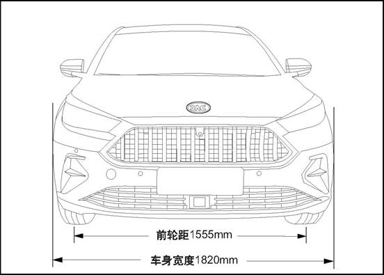
Front view
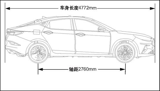
Side view
Rear view

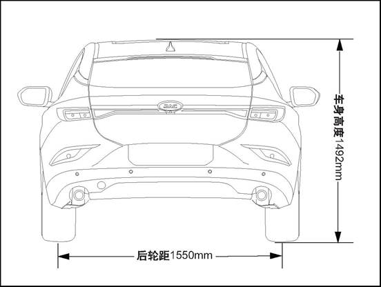
(1) Vehicle dimensional
specifications
|
Item
|
Parameter
value
|
Unit
|
|
Total
length
|
4772
|
mm
|
|
Total
width
|
1820
|
mm
|
|
Total height
(empty load)
|
1492
|
mm
|
|
Wheelbase
|
2760
|
mm
|
|
Front
tread
|
1555
|
mm
|
|
Rear
tread
|
1550
|
mm
|
(2) Maintenance parameters 1-15
|
Item
|
1.5T+6MT
|
1.5T+CVT
|
Unit
|
|
passengers
|
5
|
5
|
Man
|
|
Curb weight
|
1432
|
1440
|
Kg
|
|
Maximum weight
|
1857
|
1865
|
Kg
|
|
Front axle’s load
|
967
|
977
|
Kg
|
|
Rear axle’s load
|
890
|
888
|
Kg
|
VIII.
vehicle identification
(1)
vehicle identification code
Vehicle
identification number
Vehicle
VIN is a legal identifier.
Vehicle
identification number (VIN) position
There
are several vehicle identification codes on the vehicle,and the following 10
are the most common:
1.
Located on the dashboard in the lower left corner of the windshield, VIN can be
seen through the windscreen.
2.
Under the front passenger seat.
3.
In the vehicle glove box.
4.
On the engine cover.
5.
On the front side of right-front door inner panel
6.
Lower side of left B-column
7.
On the front of the left front door inner plate
8.
On the upper side of tailgate inner panel
9.
Refer to ECU data.
10.Refer
to MP5 data.
(2) Label
 Lable-vehicle certification
IX.
noise, vibration and abnormal sound
(1)
diagnostic information and procedures
Wind noise / air sound
△CAUTION
When the technician checks the faulty location, the assistant
should drive the vehicle. Otherwise, it may cause injuries.
You
must test the car in the car, in order to accurately confirm the location of
the wind noise. In general, wind noise has major and minor leaks. If all leaks
are not repaired during the repair, wind noise can only be reduced and wind
noise can not be completely eliminated. Test-drive maintenance staff must bring
the following tools to help diagnose the specific location of wind noise:
Stethoscope
Masking
tape
Stitch
seam
Marker
pen
Follow the procedure below to try
the road:
Select
a line, with east, south, west and north four different directions of the
straight street.
Choose
less traffic or less noise in the street, to avoid affecting the test.
The road test is conducted at the
speed at which the customer believes the noise is most pronounced or noisy, and
a speed limit of more than the legal limit is strictly prohibited. The wind
noise emitted under the following conditions is external wind noise:
Wind
noise can be heard immediately while driving down the window glass.
When the tape is attached to the
various decorative seals and gaps, the wind noise disappears immediately.
Internal wind noise is caused by air escaping from the vehicle and should be
repaired as follows:
In
determining the location of the leak, attach the tape to the body lock pillar
relief valve. The air pressure will be formed immediately inside the car, and
the wind noise will be enhanced.
Use
a stethoscope to confirm the leak location.
Use
masking tape to temporarily repair leaks.
Continue
road test to confirm whether the wind noise is completely eliminated or other
leaked parts.
After
confirming all leaks by road test, return to the repair shop and make permanent
repairs with professional and reasonable positioning methods and sealing
materials.
Abnormal sound
Please
check the following table for common abnormal noise and solutions:
|
No.
|
Symptom
|
Parts for check
|
Solution
|
|
1
|
The vehicle
generates squeaky sound when the engine speed is high.
|
Check whether
insulation panel contacts vehicle’s bottom part
|
Lift the vehicle and perform a visual
inspection
|
|
Bend the insulation panel slightly to
create a gap between it and the bottom of the vehicle body.
|
|
2
|
The front of the vehicle squeaks when
the weather is cold
|
Check the balance
bar isolation rubber sleeve
|
Cold Road Test vehicle and pass the
bumpy road, so that the front suspension can reach maximum travel.
|
|
Remove the
isolation rubber sleeve and tape the front stabilizer bar, reinstall the
isolation rubber sleeve on the tape.
|
|
3
|
Bumpy rear bass issued by the boring
abnormal sound
|
Check if the spare tire in the luggage
compartment is properly secured
|
Open the luggage compartment and inspect
the spare tire and driver's tools.
|
|
Retighten spare tires and truck tools.
|
|
Test vehicle to check whether abnormal
sound has been eliminated.
|
|
4
|
The rear of the
vehicle emits a glass percussion while traveling on a bumpy road
|
Check the rear
door lock is not properly adjusted
|
Carry out road test to check this
situation.
|
|
Loosen the lock nut and adjust the lock.
|
|
5
|
The door squeaked
|
Check if the
harness connector inside the door trim panel creaks
|
Tap the trim plate and carefully observe
if you hear a squawk
|
|
Remove the door trim and wrap the foam
padding around the harness connector according to the actual vehicle
conditions.
|
|
6
|
Squeaking when
using the door
|
Check door hinges
for lack of lubrication.
|
Push the door back and forth and listen
carefully to check whether the door squeaks.
|
|
Use rust inhibitor to lubricate the door
hinge and apply grease.
|
(2)
maintenance guide
Wind
noise / air sound
External
wind noise
Repair
methods of wind noise leak and water leakage are very close. The actual repair
procedure depends on the type of sealing components being repaired.
Abnormal
sound
Repair of
abnormal sound
Abnormal
sound comes mainly from the relative motion that should not exist between the
vehicle parts. There are three ways to repair abnormal sound:
Firmly
tighten the parts so that there is no relative movement of the vehicle during
driving.
Separate
parts so that parts do not come into contact with them at work.
Isolate
parts so that there is no abnormal noise when parts move. A uniform surface
with low-friction can be used to eliminate sticking slip between parts.
X.
Tool purchasing channel and diagnosis device
If
you want to buy special tool, please contact 4S shop in each area of JAC. For
contact information, please contact 4008889933.
|
No.
|
Diagnosis device type
|
Diagnosis device version
|
Tool
No.
|
|
1
|
3G-X431
|
V11.70
|
JAC-T1Z002
|
Engine cover and wheel fender
Ⅰ. Overview
(1) Structure Outline
Components
location map

Engine
cover assembly
Engine
cover lock assembly
Engine
cover wire assembly
4.
Left fender assembly
5.
Engine bonnet stay bar
(2)
maintenance and technical parameters
|
Area
|
Engine cover and fender
|
Engine cover and fender
|
Engine cover and the front headlights
|
Engine cover and front bumper
|
|
Clearance
|
3.5±1.0mm
(S ≤ 1.0)
|
3.5±1.0mm
(P ≤ 1.0,S ≤ 1.0)
|
4.5±1.5mm
(P ≤ 1.5,S ≤ 1.5)
|
3.5±1.5mm
(P ≤ 1.0)
|
|
Flush
|
-1.0±1.0mm
(P ≤ 1.0,S ≤ 1.0)
|
-1.0±1.0mm
(P ≤ 1.0)
|
N/A
|
-1.0±1.5mm
(P ≤ 1.0)
|
|
Basis
|
Wheel
fender
|
Wheel
fender
|
|
Front bumper
|
(3) Torque parameter
|
No.
|
Project
|
Torque
(N·m)
|
|
1
|
Engine bonnet assembly and hinge fixing
bolt
|
25~29
|
|
2
|
Engine
cover lock fastening bolt
|
7~11
|
|
3
|
Engine bonnet open handle base fixing
screw
|
|
|
4
|
Engine bonnet hinge and vehicle body
fixing bolt
|
25~29
|
|
5
|
Wheel
fender fixing bolt
|
9~11
|
|
6
|
Engine
bonnet stay bar fixing bolt
|
7~11
|
(4)
Maintenance precautions
1.
Prevent damage or scratches when disassembling and installing components.
2.
When removing the clip from the trim, wrap the straight screwdriver’s head with
cloth.
3.
When installing body trims, make sure that the clips are securely installed in
the plate holes in the body, and carefully press them in.
4.
Two people are required to dismantle the larger parts to avoid dropping.
5.
Do not use excessive force when inserting or removing some rubber trims.
2. Engine cover assembly
(2) Disassembly
1.
The hood is opened and supported by one serviceman.
△Notice
When removing or installing cover device, you must adopt bearing alternately,
in order to avoid potential cause of vehicle damage or injuries.
2.
Mark the position of the hinge relative to the hood for positioning during
installation.
3.
Disassembly of engine cover assembly
 1). Remove the two fixing bolts of engine bonnet and
hinge.
1). Remove the two fixing bolts of engine bonnet and
hinge.
△Note
Left and right side of engine cover share the same removing methods.
△Note
One person should lift the engine bonnet by hand to avoid contact with
peripheral parts.
2).
Take down engine cover from hinge.
△Notice Many people need to
cooperate to disassemble the engine compartment cover due to its enormous
weight. During disassembly, please mark hinge’s relative position on engine
hood so as to locate its position during assembly.
(3)
Installation
Assembly
engine cover assembly
1).
Install the engine bonnet into the installation position.
 2). Remove the two fixing bolts of engine bonnet and
hinge.
2). Remove the two fixing bolts of engine bonnet and
hinge.
△
Notice Many people need to cooperate to disassemble the engine compartment
cover due to its enormous weight.
△Note Left and right side of
engine cover share the same removing methods. Tightening torque 25~29N·m
Close
the engine cover
3.
Engine cover lock assembly
(2) Disassembly
1.
Open engine cover and support it with rod
2.
Remove front bumper body assembly. See front bumper assembly
Disassemble
engine cover lock assembly
 1) Take off the cable sheath 1 and
remove the cylinder pin 2 at the engine cover opening zipper end from the
engine cover lock.
1) Take off the cable sheath 1 and
remove the cylinder pin 2 at the engine cover opening zipper end from the
engine cover lock.
 2). Install four fixing bolts of
engine cover lock.
2). Install four fixing bolts of
engine cover lock.
3).
Take down engine cover lock assembly.
(3)
Installation
Assembly
engine cover lock assembly
 1). Install four fixing bolts of
engine cover lock.
1). Install four fixing bolts of
engine cover lock.
Tightening
torque 7~11N·m
2). Insert the cylinder pin 2 at the end of the open
cable into the middle position of the pulling pin seat from the opening of the
pre-installed drawing end of the lock body, rotate clockwise 90°, and then
insert the opening cable cable set 1 into the clamping slot of the drawing
fixing bracket.
2.
Install front bumper assembly
△Notice After the installation,
check the hood lock and check that the function is normal.
Harness and
engine cover lock is intact.
Close
the engine compartment cover
4. Engine bonnet open pull cable
(2) Disassembly
1.
Open engine cover and support it with rod
2.
Disassemble Front Wheel cover refer to front wheel cover
3.
Disassemble opening handle of engine cover
4.
Remove A column lower guard assembly See A column lower guard assembly
5.
Remove engine bonnet open pull cable
1). Disconnect the engine cover
lock wire drawing 1 and open the engine cover lock column.
Take
pin 2 out from the bonnet lock.
2). Disconnect the engine cover lock wire drawing 2
and open the engine cover lock column.
3).
Remove the wheel cover wire buckle, take out the engine bonnet opening pull
wire.
(3)
Installation
1.
Install engine cover opening cable
1) Drive the end of the engine cover open cable handle
into the driver's cabin through the front coaming opening hole, insert the
rubber seal sheath into the front coaming installation hole from the front
side, and then connect the wire drawing buckle.
2).
Connect the engine cover open handle base to open cable cylinder pin 1, and
clamp the cable cable sheath 2.
△Notice
pay attention to the position while connection, don't connect it wrong and keep
connection tight
3). Insert the cylinder pin 2 at the end of the open
cable into the middle position of the pulling pin seat from the opening of the
pre-installed drawing end of the lock body, rotate clockwise 90°, and then
insert the opening cable cable set 1 into the clamping slot of the drawing
fixing bracket.
2.
Install A column lower guard plate assembly
3.
Install opening handle of engine cover
4.
Install front wheel cover
Close
the engine compartment cover
△Note After the completion of
installation of engine cover lock wire drawing, for examination,
you have to
ensure that the engine cover lock control wire drawing and engine cover lock
assembly in good function and in good condition.
5. Opening handle of engine cover
(2)
Disassembly
1.
Disassemble opening handle of engine cover
1). Remove the opening handle of engine cover.
(3) Installation
1. Install opening handle of engine cover
6. Engine bonnet stay bar
(2)
Disassembly
1.
Open the engine cover
△Note Remove and install the bonnet
strut. One maintenance worker opens and supports the bonnet strut. Another
removes the bonnet strut. Prevent hood from slipping off and causing injuries.
Disassemble
the engine cover supporting rod
 1). Remove the 2 bolts that fix the bonnet pole to the
car body.
1). Remove the 2 bolts that fix the bonnet pole to the
car body.
2).
Take down the engine bonnet stay bar mounting bracket, and remove the engine
bonnet stay bar.
(3)
Installation
Install
the supporting rod of engine cover
1)
Install and protect the bonnet pole into the bonnet pole.
2).
Move the engine cover strut and mounting bracket to the mounting position.
△Note While closing, clamp the engine cover rod into the
snap joint of engine cover.
3). Install the 2 bolts to fix the
engine cover pole to the car body.
Tightening
torque 7~11N·m
Close
the engine cover
7. Engine
cover hinge assembly
(2) Disassembly
1.
Disassemble engine cover assembly see engine cover assembly
2.
Disassemble engine cover hinge
1). Remove the 2 bolts of the
bonnet hinge and body mounting.
2).
Remove the engine cover hinge.
(3) Installation
1.
Install engine cover hinge
1).
Shift the engine bonnet hinge to the installation position.
2). Install the 2 bolts of the
engine cover hinge and body fixing.
Tightening torque 25~29N·m
2.
Install engine cover
(4) adjustment of the clearance and
side difference of engine cover
1.open
and support the engine cover
Adjust
the engine cover
Loosen
the fastening bolt between the engine cover and the hinge.
Adjust the engine hood
and watch it with fender and clearance around the headlight to ensure a
balanced interval between engine cover and headlight, fender, and that the
engine cover lock hook and lock body mesh in good condition.
Adjust
the clearance between the fender and hood, try to keep the engine cover and
fender of the seam in line with the requirements of 3.5mm.
△Notice
Move the engine cover on the left, right, front and backward to complete the
adjustment.
Close
the engine hood, examine the sealing situation.
Fasten
the engine cover hinge bolt.
Tightening torque 25~29N·m
6). According to the engine cover
face situation to adjust the engine cover buffer block to the appropriate
location, ensure the engine, the bartender bar and fender are without
interference in the process of closing.
Close
the engine cover.
VIII. Wheel fender
(1) Special tools
(None)
(2) Disassembly
open
and support the engine cover
2.
Disassemble left front doorsill guard panel assembly
3.
Disassemble front triangular cover board. Refer to “front triangular board”
4.
Disassemble Front Wheel cover refer to front wheel cover
5.
Remove front bumper body assembly. See front bumper assembly
6.
Remove the front bumper retaining bracket refer to the front bumper left
retaining bracket
7. Remove
the front combination lamp assembly. See front combination lamp assembly
8.
Disassemble the front side door assembly See left front side door assembly
9.
Remove the vent cover assembly See vent cover assembly
10.
Remove wheel fender
1). Remove the cover plate assembly of the lower wing.
2).
Remove the 2 fixing bolts connecting the rear side of the wing panel to the
body.
3).
Remove the 4 fixing bolts connecting the front and lower side of the wing panel
to the body.
4).
Remove the 3 fixing bolts attached to the upper part of the wing plate and the
body.
5). Take down the fender.
(3) Installation
Install
wheel fender
1).
Move the wing plate to the installation position.
2).
Install the 3 fixing bolts attached to the upper part of the wing plate and the
body.
Tightening torque 9~11N·m
3)
install 4 fixing bolts connecting the front and lower sides of the wing panel
with the body.
Tightening torque 9~11N·m
4).
Install 2 fixing bolts connecting the rear side of the wing panel with the body.
Tightening torque 9~11N·m
5). Install wheel fender cover board assembly.
2. Install
the vent cover assembly
3.
Install left front door assembly
4.
Install the front combination lamp assembly
5.
Install front bumper left fixing bracket
6.
Install front bumper assembly
7.
Install front wheel cover
8.
Install the front triangular cover plate
9.
Install the front sill guard plate assembly
10.
Close the engine compartment cover
△Notice
The left, right front wheel fender replacement step is the same.
△check
whether the fender has been assembled in position, and the clearance between fender
and vehicle body should be appropriate. If not, re-adjust or re-assemble the
fender.
Ⅸ.
Ventilation cover water retaining strip
(2) Disassembly
1.
Open the engine cover
2.
Disassemble ventilation cover water retaining strip
1) Remove the sealing strip slowly
by hand from one end of the strip until all the strips are removed.
△Note:
Do not use force to pull the seal when removing.
(3)
Installation
1.
Disassemble ventilation cover water retaining strip
1)
Connect the rubber strip to the position along the end of the ventilation
cover.
△Notice the duct vent is partially
oriented toward the head.
2). Strike the sealing strip with a
rubber hammer and install it in place, and the adhesive strip has no wrinkle
and visibly loosens after being fastened.
△Notice When installing, use a
rubber hammer to strike the seal without too much force to prevent damage to
the seal.
Close the engine cover
X.
Engine cover sealing strip
(2) Disassembly
1.
Open the engine cover
2.
Disassemble engine cover sealing strip
1).
Remove the sealing strip buckle with the tool and remove the sealing strip.
(3)
Installation
1.
Install engine cover sealing strip
1). Attach the snaps on the seal to
the inner plate mounting holes and install the seals.
△Notice
When installing, pay attention to the alignment of the buckle with the hole to
prevent the buckle from being damaged.
Close
the engine cover
Front and rear bumpers
I. Overview
(1) Structure outline
Front
bumper assembly location map

1.
Front bumper assembly 2.
front grille assembly
Rear
bumper location map

1.
Rear bumper assembly
2.
Install rear anti-collision beam assembly
3.
Rear bumper right fixing bracket
4.
The left fixing bracket of rear bumper
(2) Torque parameter
|
sequence
|
Item
|
Torque
(N·m)
|
|
1
|
Front anti-collision beam assembly and
front end bracket fixing bolt
|
20~25
|
|
2
|
Rear anti-collision beam assembly and
vehicle body fixing screw
|
9~11
|
|
3
|
Front bumper and anti-collision beam
fixing bolt
|
|
|
4
|
front bumper and front wheel fender
fastening bolts
|
|
|
5
|
Connecting screws for front bumper to
front frame assembly
|
|
|
6
|
Connecting screw for front bumper to
guide plate
|
|
|
7
|
Front
anti-collision beam fixing bolt
|
|
|
8
|
The
cover plate on the front bumper is connected with the screws on the front
bumper
|
|
|
9
|
Rear bumper and body fixing screw
|
|
|
10
|
Rear bumper bracket and body fixing
screw
|
|
|
11
|
The front bumper fixing bracket and the
body and wing fixing screws
|
|
|
12
|
Front
grille fixing screw
|
|
(3) Maintenance
precautions
The
bumper is a resin material. Do not make it contact grease or other corrosive
chemicals . If you touch it accidentally, wash it with clean water immediately.
To
easily assemble and disassemble the bumper, the vehicle should be placed in the
lift machine, and ensure that the lift safety is locked.
When
dismantling the bumper, two people should be in operation, so as not to damage
the bumper in terms of falling on the ground.
When
the bumper is disassembled, the soft protective film is used to protect the
outer surface of the bumper so as not to be scratched.
Do
not force too much when dismantling the decoration, so as not to cause the
parts to deform and to be damaged.
6.
When assembling the rear bumper, snap it into place with the bumper fixing
bracket.
II. Front bumper assembly
(2) Disassembly
1.
Open the engine cover
2
Disconnect the negative port.of the battery
lift
the vehicle
4.
Disassemble front bumper assembly
 1) Remove the 5 fixing screws 2
connected to the front bumper and the guide plate, and remove the 4 buckles 1
connected to the front bumper and the front wheel cover.
1) Remove the 5 fixing screws 2
connected to the front bumper and the guide plate, and remove the 4 buckles 1
connected to the front bumper and the front wheel cover.
 2). Remove the 7 expansion buckles
2 connected to the front bumper assembly and the front skeleton Assembly,
2). Remove the 7 expansion buckles
2 connected to the front bumper assembly and the front skeleton Assembly,
Remove 4 screws 1 from the front
frame assembly.
3).
Remove 1 screw 2 and 2 buckles on the left and right side of the connection
between the front bumper and the wheel cover
 1
1
4).
Remove the 2 fixing bolts connecting the middle part of the front bumper to the
plate mounting plate.
5). Gently remove the front bumper
to detangle the clamped relationship between the front bumper
and the front bumper retaining
bracket.

 6) disconnect the panoramic parking
front camera wire harness connector 1 and front anti-collision radar wire
harness connector 2 inside the front bumper.
6) disconnect the panoramic parking
front camera wire harness connector 1 and front anti-collision radar wire
harness connector 2 inside the front bumper.
(3)
Installation
1.
Install front bumper assembly
 1). Move the front bumper to the installation
position and connect the panoramic parking front camera wire harness connector
1 and front anti-collision radar wire harness connector 2 inside the front
bumper.
1). Move the front bumper to the installation
position and connect the panoramic parking front camera wire harness connector
1 and front anti-collision radar wire harness connector 2 inside the front
bumper.
 2). Insert the front bumper into
the front bumper fixing bracket.
2). Insert the front bumper into
the front bumper fixing bracket.
△Notice When the front bumper
assembly is assembled, it is put in place with the bumper fixed bracket card.
Connected
in place After installation, check whether there is a surface difference and
clearance
between
the bumper and the body fit.
3)
Install 2 fixing bolts connecting the middle part of the front bumper with the
front anti-collision beam.
Tightening
torque unconfirmed N·m
4). Remove 1 screw 2 and 2 buckles
on the left and right side of the connection between the front bumper and the
wheel cover
1
Tightening
torque unconfirmed N·m
5).
Remove the 7 expansion buckles 2 connected to the front bumper assembly and the
front skeleton Assembly,
 4 pieces of screws.
Tightening
torque unconfirmed N·m
6). Install 5 fastening screws 2 in
the lower end of the front bumper assembly connected to the guide plate, and
install 4 buckles 1 in the front bumper connected to the front wheel cover.
Tightening
torque unconfirmed N·m
2.
Place down the car.
3.
Connect the battery negative cable.
Close
the engine compartment cover
III.
Front anti-collision beam assembly
(2) Disassembly
1.
Open the engine cover
2
Disconnect the negative port.of the battery
3.
Remove front bumper body assembly. See front bumper assembly
4.
Remove the tweeter. See Tweeter
5.
Remove the woofer. See the woofer
6.
Disassemble the front anti-collision beam assembly
 1) Disconnect the outdoor temperature
sensor wire harness connector 1, remove the outdoor temperature sensor,
disconnect the outdoor temperature sensor wire harness buckle 3, and separate
the wire harness. Remove 1 fixing bolt 2 in the middle of the front
anti-collision beam.
1) Disconnect the outdoor temperature
sensor wire harness connector 1, remove the outdoor temperature sensor,
disconnect the outdoor temperature sensor wire harness buckle 3, and separate
the wire harness. Remove 1 fixing bolt 2 in the middle of the front
anti-collision beam.
2).Remove
the left and right 4 fixing bolts of front anti-collision beam assembly and
vehicle body girder.
 Remove 1 fixing bolt 2 for each left and right
connecting the front collision beam assembly to the front module.
Remove 1 fixing bolt 2 for each left and right
connecting the front collision beam assembly to the front module.
3).
Take down the front anti-collision beam assembly.
(3)
Installation
1.
Install the front anti-collision beam assembly
1).
Align the front anti-collision beam assembly to the installation position.
2).
Install the left and right 4 fixing bolts of front anti-collision beam assembly
and vehicle body girder.
 Install 1 fixing bolt 2 for each left and right
connecting the front collision beam assembly to the front module.
Install 1 fixing bolt 2 for each left and right
connecting the front collision beam assembly to the front module.
Tighten
torque 20~25N·m
3). Connect the outdoor temperature sensor wire
harness connector 1, install the outdoor temperature sensor, and connect the
outdoor temperature sensor wire harness buckle 3. 1 fixing bolt 2 in the middle
of the anti-collision beam before installation.
Tightening
torque unconfirmed N·m
2.
Install the woofer
3. Install loudspeakers
4.
Install front bumper assembly
5.
Connect the battery negative cable
Close
the engine compartment cover
Ⅳ. Front bumper upper cover
(2) Disassembly
1.
Open the engine cover
2.
Disconnect the negative port.of the battery
3.
Remove front bumper body assembly. See front bumper assembly
4.
disassemble front bumper upper cover
 1) Remove the 2 wire harness
buckles connected to the cover plate on the front bumper and the panoramic
parking front camera.
1) Remove the 2 wire harness
buckles connected to the cover plate on the front bumper and the panoramic
parking front camera.
2).
Remove the 5 fixing screws connecting the cover plate of the front bumper with
the front bumper.

 3) Remove the 7 card plates
connected to the front bumper upper cover plate and remove the cover plate of
the front bumper.
3) Remove the 7 card plates
connected to the front bumper upper cover plate and remove the cover plate of
the front bumper.
(3) Installation
1.
Install front bumper upper cover
1).
Move the cover plate of the front bumper to the installation position and
connect the 7 boards connected
 with the cover plate of the front
bumper to the front bumper.
with the cover plate of the front
bumper to the front bumper.
2).
Remove the 5 fixing screws connecting the cover plate of the front bumper with
the front bumper.
Tightening torque undetermined
3) Remove the 2 wire harness
buckles connected to the cover plate on the front bumper and the panoramic
parking front camera.
2.
Install front bumper assembly
3.
Connect the battery negative cable.
Close
the engine compartment cover
V. Front grille assembly
(2) Disassembly
1.
Open the engine cover
2
Disconnect the negative port.of the battery
3.
Remove front bumper body assembly. See front bumper assembly
4.
Remove the panoramic parking front camera. See panoramic parking front Camera
5.
Disassemble the front JAC Motors label refer to the JAC Motors label
6.
Disassemble the upper cover of front bumper. Please refer to “upper cover on
front bumper”
7.
Disassemble front grille assembly
1).
Remove the 4 fixing screws connecting the front grille assembly to the front
bumper body.

2).
Remove 20 boards that are fixed to the front grid assembly and connected to the
front bumper body.
 Remove front grille assembly.
(3)
Installation
Install
front grille assembly
1).
Move the front grid assembly to the installation position and secure the
clamping plate.
2).
Remove the 4 fixing screws connecting the front grille assembly to the front
bumper body.
Tightening torque unconfirmed
N·m
2.
Install front bumper upper cover
3.
Install front JAC motors labels
4.
Install panoramic parking front camera
5.
Install front bumper assembly
6. Connect
the battery negative cable.
7.
Close the engine compartment cover
(2) Disassembly
1.
Open the engine cover
2
Disconnect the negative port.of the battery
3.
Open the tail door to the largest part and remove the rear wheel cover. Refer
to the rear wheel cover
4.
Disassemble tail lights assembly refer to tail lights assembly
5.
Disassemble rear bumper assembly
1).
Pry open 1 screw cover plate on each side of the rear bumper, and remove the
rear bumper and body solid
lower shell left/right side 1
fixing screw.
2) remove 2 expansion buckles on
the left and right sides of the upper end of the rear bumper near the lower end
of the taillight..
3).
Remove the 4 buckles connected to the rear bumper lower end on the rear
anti-collision beam bracket.
4 Gently pull off the rear bumper
to disengage it from the rear bumper fixing bracket;
5)
Disconnect the wire harness connector of the back door foot induction antenna.
6). Disconnect the rear bumper wire
harness connector.
7).
Remove the rear bumper.
(3)
Installation
Install
rear bumper assembly
1) connect the rear bumper wire
harness connector.
2) Disconnect the wire harness
connector of the back door foot induction antenna.
3).
Insert both ends of the rear bumper into the mounting bracket and connect the
lower end of the rear bumper to
the 4 buckles on the rear
anti-collision beam bracket.
△Notice When assembling rear
bumper, the bumper fixed support card and the rear bumper should be connected
in place. After installation, check whether there is a surface difference and
clearance between the bumper and the body fit.
4) remove 2 expansion buckles on
the left and right sides of the upper end of the rear bumper near the lower end
of the taillight..
5)
Install the rear bumper and the left and right screws fixed by the car body,
and cover the cover.
Tightening torque undetermined
2.
Install tail lights assembly
Close
tail door
Connect
the battery negative cable.
Close
the engine compartment cover
Ⅶ.
Rear anti-collision beam assembly
(2) Disassembly
Open
the tailgate
2.
Open the engine cover
3
Disconnect the negative port.of the battery
4. Disassemble
tail lights assembly refer to tail lights assembly
5.
Remove the Rear bumper assembly Refer to the rear bumper assembly
 6. Disassemble the rear anti-collision beam assembly
1 ). Remove the left and right 2
fixing bolts of the rear anti-collision beam assembly and the vehicle body, and
remove the rear anti-collision beam assembly.
(3)
Installation
1.
Install rear anti-collision beam assembly
 1). Install the rear bumper and the left and right
screws fixed by the car body, and cover the cover.
1). Install the rear bumper and the left and right
screws fixed by the car body, and cover the cover.
1) Install the rear bumper anti-collision beam and fix
the
left and right bolts connecting the rear anti-collision beam assembly to the
body.
Tightening
torque 9~11N·m
2.
Install rear bumper assembly
3.
Install tail lights assembly
4.
Connect the battery negative cable
5.
Close the engine compartment cover
6.
Close the tail door
Ⅷ.
Rear bumper left fixing bracket
(2) Disassembly
Open
the tailgate
2.
Open the engine cover
3
Disconnect the negative port.of the battery
4.
Remove the Rear bumper assembly Refer to the rear bumper assembly
 5. Remove the left fixing bracket of rear bumper
1). Remove the 5 bolts that fix
rear bumper left/right fixing bracket and vehicle body, and take down the
left/right fixing bracket of rear bumper.
△Notice The left one and right
one share the same removing and installing methods.
(3) Installation
1. Install left/right fixed support
on rear bumper
1). Put rear bumper left/right
fixing bracket at installation place, and install the 5 screws that fix rear
bumper left/right fixing bracket and vehicle body.
Tightening
torque unconfirmed N·m
Install
rear bumper assembly
3.
Connect the battery negative cable
Close
the engine compartment cover
Close
tail door
Ⅸ.
Left fixing bracket of front bumper
(2) Disassembly
1.
Open the engine cover
2
Disconnect the negative port.of the battery
3.
Remove front bumper body assembly. See front bumper assembly
4.
Remove the front bumper left retaining bracket
1) Remove the 4 fixing screws on the left fixing
bracket of the front bumper.
2).
Remove the left front bumper fixing bracket.
△Notice
The left one and right one share the same removing and installing methods.
(3)
Installation
1.
Install front bumper left fixing bracket
1) Clip the front bumper left fixed bracket into the
installation position.
2)
Remove the 4 fixing screws on the left fixing bracket of the front bumper.
Tightening
torque undetermined
2.
Install front bumper assembly
3.
Connect the battery negative cable.
4.
Close the engine compartment cover
Front door
I. Overview
(1) Structure
outline
Exploded
view

1.Bottom
hinge of left front door
2.
Front side door stopper
3.
Left front door up hinge
4.
Left front door assembly
5.
Lock body and fastener of left-front door
6.
Left front door outer handle assembly
7.
Left front door outer handle lock cylinder cover
8.
Left Front Door Lock hook
(2) Torque parameter
|
sequence
|
Item
|
Torque
(N·m)
|
|
1
|
Outer
handle fastening bolts of front door
|
7~11
|
|
2
|
Front door lock body and fastener
assembly fixing bolt
|
6~10
|
|
3
|
Front door hinge side fastening bolts of
the door
|
30~36
|
|
4
|
Front door hinge side fastening bolts of
the door
|
30~36
|
|
5
|
Limiting stopper of front door
|
7~11
|
|
6
|
front door limiting stopper fastening
nuts of the door
|
20~24
|
|
7
|
Front door outer weather strip fixing
bolt
|
3~5
|
|
8
|
Front
door window fixing bolt
|
7~11
|
|
9
|
Front
door lock hook fixing bolt
|
13.5~17.5
|
|
10
|
Front door window regulator fixing bolts
|
7~11
|
|
11
|
Mounting bracket fixing screw for front
door interior panel
|
7~11
|
|
12
|
Front door window rear guide rail fixing
bolt
|
7~11
|
II. Left front door assembly
(2) Disassembly
△Note:
The removal and installation methods of left front door assembly and right
front door assembly are similar.
1.
Open the engine cover
2
Disconnect the negative port.of the battery
3.
Disassemble left front door assembly
 1). Remove the 1 bolts that connect
the shift mechanism mounting bracket to the vehicle body.
1). Remove the 1 bolts that connect
the shift mechanism mounting bracket to the vehicle body.
 2). Mark the position of the upper
and lower hinges on the door and remove the upper and lower hinge door sides
2). Mark the position of the upper
and lower hinges on the door and remove the upper and lower hinge door sides
2
fixing bolts.
△Notice When dismantling, it
should be carried out many times and must not be done in once. It should be
dismantled from the bottom up.
△Notice marking the corresponding
position of each bolt is helpful to adjust clearance plane difference of door
assembly.
3). Unplug the front door harness, disconnect the
front door harness, and lift the door.
△Notice
The door is heavy and needs to be done with the assistance of another
maintenance man.
(3) Inspection
1.
Check door hinges
1
) . Inspect the hinge rotation for lubrication. If necessary, add lubricating
grease.
(4) Installation
△Note
Fastening should be carried out several times during installation. Do not
tighten all bolts in one time.
1.
Install left front door assembly
1). Connect front door wire harness
connector and install wire harness rubber sleeve.
2). Install the door on the hinge according to the
marking position, slightly regulate the upper/lower hinge door side
.
Tightening
torque 30~36N·m
△Note
the parting and surface difference between front door and side components
should be the same.
3). The limiting stopper of 1 fixed
bolts is connected with the body.
Tightening
torque 20~24N·m
△Note: After the door assembly is
installed, make necessary assembly adjustments to ensure doors open and close
normally, and paint the hinge assembly bolt head (body color) to maintain
corrosion resistance.
2.
Connect the battery negative cable.
Close
the engine compartment cover
III. Front door waterproof membrane
(2) Disassembly
1.
Open the engine cover
2
Disconnect the negative port.of the battery
3.
Remove front door interior panel assembly see front door interior panel
assembly
4.
Remove front door waterproof membrane
1) Remove the 2 screws fixing front
door inner trim panel mounting bracket.
2)
Remove the wiring harness fixing buckle, and separate waterproof membrane and
take it down.
(3)
Installation
1.
Install front door waterproof membrane
1) Attach the waterproof membrane to the mounting
position of the the door body, and then install the wiring harness fixing
buckle.
△Note: When assembling the
waterproof membrane, the waterproof membrane should not be allowed to cover the
mounting hole of the door trim panel.
△Note:
Do not touch the adhesive surface so as not to weaken the effect of
re-adhesion.
△Note:
The waterproof membrane comes with butyl adhesive, no need to reapply the
adhesive.
2)
Remove the 2 screws fixing front door inner trim panel mounting bracket.
Tightening torque 7~11N·m
Install
front door trim panel assembly
3.
Connect the battery negative cable.
Close
the engine compartment cover
IV.
Front Door Lock and Fastener
(2) Disassembly
1.
Lift the window to the top
2.
Open the engine cover
3
Disconnect the negative port.of the battery
4.
Remove front door interior panel assembly see front door interior panel
assembly
5.
Remove the front door waterproof membrane. Refer to the front door waterproof
membrane
6.
Remove the front door handle assembly refer to the front door outer handle
assembly
7. Disassemble door lock and
fastener on the left-front door
1)
Disconnect the front side door lock body and latch assembly wire harness
connector.
2).
Remove the three hexagon socket screws that fix the front side door lock body
and lock assembly.
3). Break the connection between
the pull rod of the wire-drawing lock core and the lock body outside the door, and
take out the base of the outer opening handle and the lock body as a whole from
the door.
4).
Separate the lock body from the open handle base.
(3)
Installation
Assemble door lock and fastener on
side-front door
1) Connect the lock body to the
open handle base, put the whole into the door mounting position and fix the
base.
2).
Connect the wire drawing lock core pull rod and the lock body outside the door.
3).
Remove the three hexagon socket screws that fix the front side door lock body
and lock assembly.
Tightening torque 6~10N·m
Connect
the wire harness connector of the front side door lock body and fastener.
2. Install front door outer handle assembly
3.
Install front door waterproof membrane
4.
Install front door trim panel assembly
5. Connect
the battery negative cable
Close
the engine compartment cover
(4) inspection
If
the riveting parts of the lock body, the moving parts have painted lubricating
grease
If
the riveting parts if tight or not
If
the moving parts is flexible and have clamping and abnormal sound situation
If
the coating and chemical treatment layer of the lock body metal part is even or
if it has obvious defect
5.
Check whether the door switch is normal and whether the door lock is secure. If
not, please adjust or re-assemble the lock
V. Locking hook assembly
(1) Special tools
(None)
(2) Disassembly
1.
Open the front door
2.
Disassemble locking hook assembly
1). Remove the 2 inner hex screws that fix the lock
hook assembly, and remove the lock hook assembly.
△Note:
Before removing, mark the current lock hook position.
△Notice
The front and rear door lock hooks are dismounted in the same way.
(3) Installation
1.
Install locking hook assembly
1).
Place the lock hook assembly into installation position, align to the mark
position before, and
install the 2 inner hex screws that
fix the lock hook assembly.
Tightening
torque 13.5~17.5N·m
△Note:
Ensure the lock hook is in the middle of the door lock.
Close
the Door
Ⅵ. Front door outer handle assembly
(2) Disassembly
1.
Lift the window to the top
2.
Open the engine cover
3
Disconnect the negative port.of the battery
4.
Remove front door interior panel assembly see front door interior panel
assembly
5.
Remove the mechanical lock core. Refer to the mechanical lock core (left front
door only).
6.
Disassemble front door outer handle assembly
1)
Disconnect the wire harness connector of PEPS antenna on the left front door
handle.
2). Remove the latch that connects
the left front door handle to the door knob bracket.
 3). Pull the door handle outward and remove the front
door handle assembly backward.
3). Pull the door handle outward and remove the front
door handle assembly backward.
4)
Take out the base of the open handle and disconnect the connection between the
base and the drawing wire of the open handle.
(3)
Installation
1.
Install front door outer handle assembly
1) Connect the open handle base and
draw wire, fix the base to the door and install the handle from the ou
tside to the handle base.
2). Remove the latch that connects the left front door
handle to the door knob bracket.
3)
Disconnect the wire harness connector of PEPS antenna on the left front door
handle.
2. Installation of mechanical lock
core (left front door only)
3.
Install front door trim panel assembly
4.
Connect the battery negative cable
Close
the engine compartment cover
VII. Front side door stopper
(2) Disassembly
1.
Open the engine cover
2
Disconnect the negative port.of the battery
3.
Remove front door interior panel assembly see front door interior panel
assembly
4. Disassemble limiting stopper of front door
1).
Remove the 1 bolt that connects the shift mechanism mounting bracket to the
vehicle body.
2).
Remove the 2 bolts that connect the shift mechanism mounting bracket to the
vehicle door.
3). Take down the limiting stopper
(3)
Installation
1.
Install limiting stopper of front door
1). Place the limiter in the
installation position and install the two fixing nuts connected with the
limiter and the door.
Tightening
torque 7~11N·m
2). Install the 1 bolt that
connect the stopper and the vehicle body.
Tightening
torque 20~24N·m
Install
front door trim panel assembly
3.
Connect the battery negative cable.
Close
the engine compartment cover
VIII. Front door hinge
(2) Disassembly
1.
Open the engine cover
2
Disconnect the negative port.of the battery
3.
Disassemble the front side door assembly See left front side door assembly
4.
Disassemble wheel fender refer to ‘wheel fender’
5.
Disassemble the front door hinge
1).
Remove the 2 fixing bolts connecting vehicle body and the upper/lower hinge.
 2. Take down the front door hinge
(3)
Installation
1.
Install the front door hinge
1).
Install the 2 fixing bolts connecting vehicle body and the upper/lower hinge.
Tightening torque 30~36N·m
Install
wheel fender
3.
Install left front door assembly
4.
Connect the battery negative cable
Close
the engine compartment cover
IX. Front door inner weather strip
(2) Disassembly
1.
Regulate the door window to the lowest
2.
Open the engine cover
3
Disconnect the negative port.of the battery
4.
Disassemble front triangular cover board. Refer to “front triangular board”
5.
Remove front door interior panel assembly see front door interior panel
assembly
6. Remove the front door inner weather strip
1).
Pry one end of the weather strip, and take it down slowly with hands.
△Note:
Do not use excessive force when disassembling, as it may cause part
deformation.
(3)
Installation
1. Install the front door inner
weather strip
1)
Align the split bar in the door with the sheet metal stop, keep the gap of
1~2mm, visually measure the distance between the two ends of the split bar and
the glass cloth trough, and then slowly install the split bar in the door in
place.
2.
Install the front triangular cover plate
3.
Install front door trim panel assembly
4.
Connect the battery negative cable
Close
the engine compartment cover
X.
Front door outer weather strip
(2) Disassembly
1.
Regulate the door window to the lowest
2.
Open the engine cover
3
Disconnect the negative port.of the battery
4.
Disassemble front triangular cover board. Refer to “front triangular board”
5.
Remove front door interior panel assembly see front door interior panel
assembly
6.
Remove left outer rearview mirror Assembly refer to left outer rearview mirror
Assembly
7. Remove the front door outer weather strip
1)
Remove 1 fixing screw at the rear end of the water splitting strip outside the
fixed door, and take out the water splitting strip outside the front door
upward.
△Note:
Do not use excessive force when disassembling, as it may cause part
deformation.
△Note:
Check the weather strip in vision after disassembly, if there is deformation
found, please replace it.
(3)
Installation
1. Install the front door outer weather strip
1)
Align the water splitting bar outside the door with the metal plate stop, keep
the gap between 1~2mm, align the rear end of the outside water splitting bar
with the rear end of the door metal plate, and then slowly install the water
splitting bar outside the front door in place.
2)
Install the 1 fixing bolt at the rear end of vehicle door outer weather strip.
Tightening
torque 3~5 N.m
2.
Install left outer mirror assembly
3.
Install front door trim panel assembly
4.
Install the front triangular cover plate
5.
Connect the battery negative cable
6.
Close the engine compartment cover
7.
Lift the door window up
XI. Front door frame rubber strip
(2) Disassembly
1. Remove the front door frame
rubber strip;
1).
Tilt the sealing strip from the position near the lock with the tool.
2).
Slowly remove the sealing strip.
△Note: Do not use force to pull the
seal when removing.
(3) Installation
1. install the rubber strip of front door's frame
1).
Align the starting mark on the sealing strip with the corner above the door
stop of the body door frame.
2).
Insert the sealing strip into the car body stop and fix it by hand.
△Notice
clamp tight the corners.
3
Tap the seal with a rubber mallet and install it in place.
△Notice When installing, use a
rubber hammer to strike the seal without too much force to prevent damage to
the seal.
XII. Front door first rubber strip
(2) Disassembly
1.Remove
the front door first rubber strip
 1) Pry up the first rubber strip from one side and
separate the strip from vehicle door.
1) Pry up the first rubber strip from one side and
separate the strip from vehicle door.
pull
out the rubber strip slowly.
3).
Use the buckle driver to remove the buckle from the door plate buckle hole.
(3)
Installation
1. assemble first rubber strip on
side-front door
put
the first rubber strip on assembling position.
2)
Glue strip of front side door head slot into corresponding slot..
3)
clamp the buckle on rubber strip to corresponding position.
(2) Disassembly
1.
Remove front door interior panel assembly see front door interior panel
assembly
2.
Remove the front door waterproof membrane. Refer to the front door waterproof
membrane
3.
Remove the front door inner weather strip. Refer to the front door inner
weather strip
4.
Remove the front door outer weather strip. Refer to the front door outer
weather strip
5. Remove the front door window.
1).
Regulate the door window the the proper position, to make it easy to remove the
fixing bolts of front door window.
2). Remove the 2 bolts fixing the
front car window glass, deflect forward and slowly pull out the front door
glass upward.
(3)
Installation
1. Install the front door window
1).
Put the front door glass inside the door.
2).
Install the 2 bolts of front door window.
Tightening torque: 7 ~ 11N.m
2.
Install the front door outer weather strip
3.
Install the front door inner weather strip
4.
Install front door waterproof membrane
5.
Install front door trim panel assembly
XIV.
Front door window regulator
(2) Disassembly
1.
Remove front door interior panel assembly see front door interior panel
assembly
2.
Remove the front door waterproof membrane. Refer to the front door waterproof
membrane
3.
Remove the front door inner weather strip. Refer to the front door inner
weather strip
4.
Remove the front door window. Refer to the front door window
5.
Remove the front door window regulator
1) Disconnect the wire harness
connector on the glass elevator motor.
2) Remove the three bolts fixing
the glass lifter of the front door and loosen the upper bolts for 3-5 teeth.
3).
Take out the glass regulator.
(3)
Installation
1.
Install the glass lifter of side front door
1) Put the glass elevator of the
front door into the door, assemble and tighten the bottom bolt, then tighten
the top bolt, and finally assemble and tighten the middle bolt.
Tightening
torque: 7 ~ 11N.m
2).
Connect the wire harness connector on the window window lifter motor.
2. Install the front door window
3.
Install the front door inner weather strip
4.
Install front door waterproof membrane
5.
Install front door trim panel assembly
XV. Front door window groove
(2) Disassembly
1. Remove
front door interior panel assembly see front door interior panel assembly
2.
Remove the front door waterproof membrane. Refer to the front door waterproof
membrane
3.
Remove the front door inner weather strip. Refer to the front door inner weather
strip
4.
Remove the front door outer weather strip. Refer to the front door outer
weather strip
5.
Remove the front door window. Refer to the front door window
6. Remove the front door window groove
1).
Remove the glass trough along one end.
(3)
Installation
1. Install the front door window groove
1)
Align the front and rear corners of the tank and the front and rear corners of
the sheet metal for preliminary fixing of the tank.
2).
Insert the front door glass slot into the door installation position.
2.
Install the front door window
3.
Install the front door outer weather strip
4.
Install the front door inner weather strip
5.
Install front door waterproof membrane
6.
Install front door trim panel assembly
XVII.
Front door window rear guide rail
(2) Disassembly
1.
Remove front door interior panel assembly see front door interior panel
assembly
2.
Remove the front door waterproof membrane. Refer to the front door waterproof
membrane
3.
Remove the front door inner weather strip. Refer to the front door inner
weather strip
4.
Remove the front door outer weather strip. Refer to the front door outer
weather strip
5.
Remove the front door window. Refer to the front door window
6.
Remove the front door window groove
7.
Remove the front door window rear guide rail
1).
Remove 1 fixing bolt that connects the rear guide rail of the front door glass
to the door.
2). Remove the front door window
rear guide rail
(3)
Installation
1. Install
the front door window rear guide rail
1). Put the rear guide rail of the front door glass
into the door installation position.
2)
Clip the upper end of the rear guide rail of the front door into the window frame
guide rail clamping structure.
3)
Install a fixing bolt that connects the front door glass and the rear guide
rail to the car body.
Tightening
torque: 7 ~ 11N.m
2.
Install the front door window groove
3.
Install the front door window
4.
Install the front door outer weather strip
5.
Install the front door inner weather strip
6.
Install front door waterproof membrane
7.
Install front door trim panel assembly
Rear door
Ⅰ.
Overview
(1)
Structure Outline
Exploded
view

1.
Rear door bottom hinge
2.
Rear door stopper
3.
Rear door upper hinge
4.
Install the rear side vehicle door assembly
5.
Left front door outer handle assembly
6.
Install the rear door triangular board
(2) Torque parameter
|
sequence
|
Item
|
Torque
(N·m)
|
|
1
|
Back
door outer handle fixed bolt
|
7~11
|
|
2
|
Rear door hinge door side fastening bolt
|
30~36
|
|
3
|
Rear door hinge body side fixed bolt
|
30~36
|
|
4
|
Vehicle door side fixing nut of rear
vehicle door stopper
|
7~11
|
|
5
|
Vehicle body side fixing nut of rear
door stopper
|
20~24
|
|
6
|
Rear
door window fixing bolt
|
7~11
|
|
7
|
Rear door window regulator fixing bolts
|
7~11
|
|
8
|
Rear door outer weather strip fixing
bolt
|
3~5
|
|
9
|
Rear
door lock fixing bolt
|
13.5~17.5
|
|
10
|
Set screw for rear door triangular cover
|
7~11
|
|
11
|
Rear door window rear guide rail fixing
bolt
|
7~11
|
II. Rear side vehicle door assembly
(2) Disassembly
1
Open the engine compartment cover.
2
Disconnect the negative port.of the battery
3.
Disassemble rear door assembly
1).
Remove the 1 bolts that connect the shift mechanism mounting bracket to the
vehicle body.
2).
Mark the position of the upper and lower hinges on the door and remove the
upper and lower hinge door sides
2 fixing bolts.
△Notice When dismantling, it
should be carried out many times and must not be done in once. It should be
dismantled from the bottom up.
△Notice marking the corresponding
position of each bolt is helpful to adjust clearance plane difference of door
assembly.
3) Disconnect the rear door harness connector and lift
down the door.
△Notice
The door is heavy and needs to be done with the assistance of another
maintenance man.
(3).
assembly
△Notice
Fastening should be carried out several times during installation and must not
be tightened at one time.
1.
Install the rear side vehicle door assembly
1)
Connect the rear door wire harness connectors and preinstall hinge fastening
bolts.
2).
Install the door on the hinge according to the marking position, slightly
regulate the upper/lower hinge door side
4 fixing bolts.
Tightening
torque 30~36N·m
3). The limiting stopper of 1 fixed
bolts is connected with the body.
Tightening
torque 20~24N·m
△Note: After the door assembly is
installed, assembly adjustment must be performed to ensure that the door can be
opened/closed normally and the head of the hinge assembly bolt is painted (body
color).
2.
Connect the battery negative cable.
Close
the engine compartment cover
III. Rear door waterproof membrane
(2) Disassembly
1
Open the engine compartment cover.
2
Disconnect the negative port.of the battery
3.
Remove the rear door interior panel assembly see rear door interior assembly
4.
Remove the rear door waterproof membrane
1) Remove the 2 screws fixing the
rear door interior panel mounting bracket, remove the interior panel and
install the bracket.
2)
disconnect the woofer wire harness connector and remove the rear door
waterproof membrane.
(3)
Installation
1.
Install the rear door waterproof membrane
1) Attach the waterproof film to
the door body installation position and connect the woofer wire harness
connector.
△Note: When assembling the
waterproof membrane, the waterproof membrane should not be allowed to cover the
mounting hole of the door trim panel.
△Note:
Do not touch the adhesive surface so as not to weaken the effect of
re-adhesion.
△Note:
The waterproof membrane comes with butyl adhesive, no need to reapply the
adhesive.
2)
Remove the 2 screws fixing front door inner trim panel mounting bracket.
Tightening torque 7~11N·m
Install
rear door trim panel assembly
3.
Connect the battery negative cable.
Close
the engine compartment cover
IV.
Rear door stopper
(2) Disassembly
1.
Open the engine cover
2
Disconnect the negative port.of the battery
3.
Remove the rear door interior panel assembly see rear door interior assembly
4.
Disassemble the rear door stopper
1).
Remove the 1 bolt that connects the shift mechanism mounting bracket to the
vehicle body.
2). Remove the 2 fixing nuts
connected to the limiter and remove the limiter of the rear door.
(3) Installation
1.
Install rear door stopper
2).
Remove the 2 bolts that connect the shift mechanism mounting bracket to the
vehicle door.
Tightening torque 7~11N·m
2). Install the 1 bolt that connect
the stopper and the vehicle body.
Tightening
torque 20~24N·m
2.
Install the rear door trim panel assembly
3.
Connect the battery negative cable.
Close
the engine compartment cover
V.
Rear door outer handle assembly
(2) Disassembly
1.
Open the engine cover
2
Disconnect the negative port.of the battery
Disassemble
rear door interior panel assembly see rear door interior assembly
4.
Disassemble rear door outer handle assembly
1). Pry open the bolted cover and
remove the 1 hexagon socket bolt fixed by the rear door handle and door handle
bracket.
 2). Pull the rear door handle outward and remove the
rear door handle assembly backward.
2). Pull the rear door handle outward and remove the
rear door handle assembly backward.
3)
Take out the base of the open handle and disconnect the connection between the
base and the drawing wire of the open handle.
(3)
Installation
Install
rear door outer handle assembly
1) Connect the open handle base and
draw wire, fix the base to the door and install the handle from the outside to
the handle base.
2) Install 1 hexagon socket bolt
fixed by the rear door handle and door handle bracket and fasten the bolt to
plug the cover.
Tightening
torque 7~11N·m
Install
rear door trim panel assembly
3.
Connect the battery negative cable.
Close
the engine compartment cover
(2) Disassembly
1.
Remove the rear side door assembly See rear side door assembly
2. Remove the rear door hinge
1) remove the 2 fixing bolts connecting the upper
hinge to the body and remove the upper hinge.
2)
remove the 2 fixing bolts connecting the upper hinge to the body and remove the
upper hinge.
(3)
Installation
1. Install the rear door hinge
1)
Load the lower hinge and install the 2 fixing bolts connecting the lower hinge
to the body.
Tightening
torque 30~36N·m
2).
Mount the upper hinge and install the 2 fixing bolts connecting the upper hinge
to the body.
Tightening
torque 30~36N·m
2.
Install the rear side vehicle door assembly
△Note:
The parting and surface difference between rear door and side components should
be the same.
VII. Rear door frame rubber strip
The
removal and installation process of the rear door frame adhesive strip is
similar to that of the front door frame. Please refer to the front door frame
adhesive strip.
VIII. Rear door first rubber strip
The
removal and installation process of the rear door header strip is similar to
that of the front door header strip. Please refer to the front door header
strip.
Ⅸ. Rear door window
Rear
door glass is similar to front door glass, see front door glass.
X.Rear door window regulator
Rear
door glass is similar to front door glass, see front door glass.
XI. Rear door window groove
The
disassembly and installation process of the rear door glass compartment is
similar to that of the front door glass compartment. Please refer to the front
door glass compartment.
XII. Rear door window guide rail
(2) Disassembly
1.
Remove the rear door interior panel assembly see rear door interior assembly
2.
Remove the rear door waterproof membrane. Refer to the rear door waterproof
membrane
3.
Remove the rear door inner weather strip. Refer to the rear door inner weather
strip
4. Remove
the rear door outer weather strip. Refer to the rear door outer weather strip
5.
Remove the rear door window, refer to rear door window
6.
Remove the rear door window groove, refer to the rear door window groove
7. Disassemble rear door window guide rail
1)
Remove 2 fixing bolts of rear door glass guide and take out the rear door glass
guide.
(3)
Installation
1. Install rear door window guide
rail
1)
Install the rear door glass guide and install 2 fixing bolts.
Tightening torque 7~11N·m
2.
Install rear door window groove
3.
Install the rear door window
4.
Install the rear door outer weather strip
5.
Install the rear door inner weather strip
6.
Install the rear door waterproof membrane
7.
Install rear door trim panel assembly
XIII. Rear door outer weather strip
(2) Disassembly
1.
Regulate the door window to the lowest
2.
Remove the rear door outer weather strip
1)
remove 1 fixing screw at the back end of the splitter bar outside the door of
the fixed car.
2). Remove the 1 fixing screw at the front end of the
splitter bar at the rear door.
3)
Remove up the rear door outer weather strip
△Note:
Do not use excessive force when disassembling, as it may cause part
deformation.
△Note:
Check the weather strip in vision after disassembly, if there is deformation
found, please replace it.
(3)
Installation
1.
Install the rear door outer weather strip
1). Insert the outside water
splitting strip into the installation position before installing and fixing the
outside water splitting strip
1 fixing screws.
Tightening
torque 7~11N·m
2)
Install 1 fixing screw at the back end of the splitter bar outside the door
after fixing.
Tightening torque 7~11N·m
2)
Lift up the window
XIV. Rear door inner weather strip
(2) Disassembly
1.
Regulate the door window to the lowest
2.
Open the engine cover
3
Disconnect the negative port.of the battery
4.
Remove the rear door triangular panel See rear door triangular panel
5.
Remove the rear door interior panel assembly see rear door interior assembly
6.
Remove the rear door inner weather strip
1). Pry up one end of the inside
split bar and slowly remove the inside split bar from the rear door with both
hands.
△Note: Do not use excessive force
when disassembling, as it may cause part deformation.
(3)
Installation
1.
Install the rear door inner weather strip
1) Align the split bar in the door with the sheet
metal stop, keep the gap of 1~2mm, visually measure the distance between the
two ends of the split bar and the glass cloth trough, and then slowly install
the split bar in the door in place.
Install
rear door trim panel assembly
3.
Install the rear door triangular board
4.
Connect the battery negative cable
Close
the engine compartment cover
6)
Lift up the window
XV. Install the rear door
triangular board
(1)
Special tools
(2) Disassembly
1.
Open the rear door
(none)
2.
Disassemble the rear door triangular board
1). Pry off the inner triangular
cover of the rear door.
2)
Remove the 3 screws fixing the triangle cover plate and remove the triangle
cover plate.
(3)
Installation
1.
Install the rear door triangular board
1)
Move the triangular cover plate to the installation position and install 3
fixing screws.
Tightening torque 7~11N·m
2). Buckle the inner triangular
cover.
2.
Close the left rear door
Tail door and oil-filler cap
Ⅰ. Overview
(1) Structure
Outline
 Location map

 1. Tail gate gas strut (high
distribution strut)
1. Tail gate gas strut (high
distribution strut)
2.
Tail door lock assembly
3. Tail door assembly
4.
Tailgate yin-yang limit block
5.
Tail door dumper block
6.
Tailgate hook
(2) Torque parameter
|
sequence
|
Item
|
Torque
(N·m)
|
|
1
|
Tail
door lock body assembly fixing bolt
|
7~11
|
|
2
|
Tail
door lock hook fixing screw
|
22~28
|
|
3
|
Tail door hinge body side fastening bolt
|
25~29
|
|
4
|
Tail gate yin-yang stopper
|
7~11
|
|
5
|
Tail door hinge door side fixing bolt
|
30~36
|
II.
Tail door metal sheet assembly
(2) Disassembly
open
and support tail door
2.
Open the engine cover
3
Disconnect the negative port.of the battery
4.
Disassemble tail door interior trim panel assembly see tail door interior
trim panel assembly
5.
Remove the tailgate upper frame assembly See the tailgate upper frame assembly
6.
Remove tail door left/right frame Assembly refer to tail door Left/right frame
Assembly
7.
Remove left and right tail door combination lamp assembly. Refer to the “tail
door combination lamp”
8.
Remove license plate light Assembly see License Plate light Assembly
Disassemble
high - position brake lamp refer to high - position brake light
10.
Remove panoramic rear parking Camera. See Panoramic rear parking Camera
11.
Remove the buzzer. See Buzzer
12.
Remove the outer suitcase switch refer to the outer suitcase switch
13.
Remove trunk open switch bracket. See trunk open switch bracket
14.
Disassemble tail door lock assembly see tail door lock assembly
15.
Remove tailgate buffer block. See Tailgate buffer block
16.
Remove the male/female limit block of the tail gate. See the male/female limit
block of the tail gate
17.
Remove the C pillar lower guard plate and trunk side guard plate C pillar
lower guard plate and trunk side guard plate
18.
Remove C column upper guard assembly See C column upper guard assembly
19.
Remove the tail door electric strut Assembly. Refer to the tail door electric
strut Assembly (high matching)
20.
Remove tailgate sheet metal Assembly (high fitting)

 1) Disconnect the wire harness
connector 1 between the tail door and the car, and remove 2 lapping bolts 2.
1) Disconnect the wire harness
connector 1 between the tail door and the car, and remove 2 lapping bolts 2.
2).
Remove 2 bolts on left and right sides of the hinge connection between the tail
door and the tail door.
3)Disconnect the tail door harness
connector and remove the tail door.
△Note: The tailgate should always be
supported during disassembly until the tailgate can be removed from the vehicle
to prevent the tailgate from falling and injuring personnel or vehicle.
(3)
Installation
1.
Install tail door metal sheet assembly
2).
Remove 2 bolts on left and right sides of the hinge connection between the tail
door and the tail door.
Tightening torque 30~36N·m
△Notice After the tail door
assembly is completed, the tail door needs to be adjusted to ensure that the
left and right clearance, the surface difference meets the requirements. the
opening and closing should be smooth without intervention. If the deviation
exists between lock body and lock hook, please loosen the two fixing bolts of
lock hook, adjust hook to appropriate position, then re-fix the bolts.
2). Connect the tailgate wire harness connector 1 and
install 2 lat bolts 2.
2.
Install the tailgate electric strut assembly
3.
Install C pillar upper guard assembly
4. Install the C pillar lower guard
panel and trunk side guard panel assembly
5.
Install the tailgate Yang limit block
6.
Install tailgate buffer block
7.
Install tail door lock assembly
8.
Install boot switch bracket
9.
Install exterior switch of trunk
10.
Install Buzzer
11.
Install panoramic parking rear camera
12.
Install high mounted brake lamp
13.
Install license plate light assembly
14.
Install tail door left and right combination lights
15.
Install tail door left/right frame assembly
16.
Install the tailgate upper frame assembly
17.
Install tail door trim panel assembly
18.
Connect the battery negative cable.
19.
Close the engine compartment cover
20.
Close the tail door
III. Tail door hinge assembly
(2) Disassembly
1.
Open the engine cover
2
Disconnect the negative port.of the battery
3.
Disassemble tail door assembly see tail door assembly
4.
Disassemble tail door hinge assembly
1) Lift the end of the ceiling and
remove the left and right fixing bolts of the hinge of the tail door and the
body from inside the car.
2).
Remove tail door hinge assembly.
(3)
Installation
1.
Install tail door hinge assembly
1) Install 1 fixing bolt on the
left and right side of the hinge of the tail door to the car body, and cover
the tail end of the ceiling.
Tightening
torque 25~29N·m
Install
tail door assembly
3.
Connect the battery negative cable.
4.
Close the engine compartment cover
IV.
Tail door lock assembly(high configuration)
(2) Disassembly
1.
Open the engine cover
2
Disconnect the negative port.of the battery
Open
the tailgate
4.
Remove the tail door handle box, see the tail door handle box
5.
Disassemble tail door interior trim panel assembly see tail door interior
trim panel assembly
6. Disassemble tail door lock assembly
1)
Disconnect the wire harness connector 1 of the tail door lock body, remove 3
fixing bolts 2, gently move the tail door lock body to the left, and remove the
lock body after the locking body is separated from the tail door.
2) Disconnect the wire harness connector 1 of the tail
door lock actuator, remove the 3 fixing bolts 2, and pull out the tail door
lock actuator outward. Remove tail door lock assembly.
△Note
the plastic clip on the actuator can be torn when pulled out.
(3)
Installation
1.
Install tail door lock assembly
1) Clip the jaw of the tail door lock body into the
sheet metal of the tail door, connect wire harness connector 1, and install 3
bolts 2 to fix the lock body.
Tightening
torque 7~11N·m
△Note: The hook behind the door lock
should be inserted into the corresponding hole of the sheet metal when
installing the door lock body. During the installation and adjustment of the
tail door lock body, pretighten the bolt of the tail door lock body to ensure
that the lock is in the middle and then tighten the bolt.
2). Clip the door lock actuator into the sheet metal
of the door, connect the wire harness connector 1 of the door lock actuator,
and install 3 bolts 2 to fix the door lock actuator.
Tightening
torque 7~11N·m
2.
Install tail door trim panel assembly
3.
Install the tail door handle box
Close
tail door
Connect
the battery negative cable.
Close
the engine compartment cover
V. Tail door lock assembly
(2) Disassembly
1.
Open the engine cover
2
Disconnect the negative port.of the battery
Open
the tailgate
4.
Remove the tail door handle box, see the tail door handle box
5.
Disassemble tail door interior trim panel assembly see tail door interior
trim panel assembly
6. Disassemble tail door lock assembly
1)
Disconnect the wire harness connector 1 of the tail door lock body, remove 3
fixing bolts 2, gently move the tail door lock body to the left, and remove the
lock body after the locking body is separated from the tail door.
(3)
Installation
1.
Install tail door lock assembly
1) Clip the jaw of the tail door lock body into the
sheet metal of the tail door, connect wire harness connector 1, and install 3
bolts 2 to fix the lock body.
Tightening
torque 7~11N·m
2.
Install tail door trim panel assembly
3.
Install the tail door handle box
Close
tail door
Connect
the battery negative cable.
Close
the engine compartment cover
△Notice
Bolt tightening torque 7 ~ 11N · m
△Note: The hook behind the door lock
should be inserted into the corresponding hole of the sheet metal when
installing the door lock body.
△Note:
The mounting bolts of the tail door lock body are pretightened to ensure that
the lock lock body is in the middle and then tighten the bolts.
△Note:
Protect the tail door sheet metal paint when clamping.
VI. Tailgate lock hook
(2) Disassembly
Open
the tailgate
2.
Disassemble tail door sill guard assembly
3.
Remove tail door lock hook
1) remove the 2 fixing screws on
the tail door lock latch.
2).
Remove the tail door lock hook.
△Note:
Before removing, mark the current lock hook position.
(3)
Installation
1. Install tail door lock hook
1).
Place the tail door lock hook in the installation position and align it with
the marked position before removal,
and install 2 screws to fix the
tail door lock hook.
Tightening
torque 22~28N·m
△Note: pre-tighten the assembling bolts
of tail door lock, and ensure the lock buckle has aligned before tightening the
bolts.
2.
Install tailgate door assembly
Close
tail door
VII.
Tail gate pneumatic rod assembly
(2) Disassembly
open
and support tail door
2. Disassemble the tail door right gas pole assembly
Use a flat screwdriver or a
special tool to slightly pry up the car body end ball clamp plate and pull out
the brace hole from the ball head.
2). Slightly pry up the
ball-and-socket card at the end of the tailgate with a word or special tool,
and pull out the pole and socket from the ball head.
3).
Take down the pneumatic rod.
△Note: When disassembling, always
pay attention to supporting the tailgate until the disassembly is completed, to
prevent the tailgate from falling and hurting people or vehicles.
(3)
Installation
Install
pneumatic brace of tail door
1).
Put the tail gate end pole socket into door end ball head, buckle ball card.
Put
the body end supporting rod into body end ball head, buckle ball card.
Close tail door
VIII. Tail door sealing strip
(1)
Special tools
(2) Disassembly
Open
the tailgate
(none)
2. Remove tail door sealing strip
Pry
up the sealing strip from the corner.
Remove
the sealing strip slowly from the corner.
△Note:
Do not use force to pull the seal when removing.
△Note:
When disassembling, pay attention to the removal of butyl rubber, otherwise it
will pollute the sheet metal and surrounding accessories.
(3)
Installation
1. Install tail door sealing strip
1)
Molding the sealing strip to the seam and the tailgate lock alignment
positioning;
2)
Use hand to insert the sealing strip into the car body stopper and fix it well,
pay attention to the tightness at the rounded corner;
3)
Tap the seal with a rubber mallet and install it in place.
△Notice When installing, use a
rubber hammer to strike the seal without too much force to prevent damage to
the seal.
△Note: When installing, first clamp
the lower part of the door frame to two corners, then clamp the upper part of
the door frame to two corners, and finally clamp the left and right sides of
the door.
Close tail door
Ⅸ.
Tail door buffering block
(2) Disassembly
Open
the tailgate
2. Remove the tail door buffering block
1).
Remove the tail door dumper block from the tail door.
(3) Installation
1. Install the tail door buffering block
1).
Install the tail door dumper block to the installation hole of tail door inner
panel corner.
△Note:
When installing, reveal 5 thread.
Close
tail door
X. Refueling cover base assembly
(2) Disassembly
1.Remove
the rear wheel cover with reference to rear wheel cover
2.
Refueling cover base assembly
1) Open the refueling cap cover,
extend your hand to the wire drawing actuator in the body cavity, and turn
counterclockwise to remove the wire drawing actuator.
2)Rotate and screw the fuel filler
cover, and take down the withdraw wire from base seat hinge arm.
3). After priing off the clamping
contact of the refueling cap with the plastic skid, pull the refueling cap out
to the outside.
4).
Remove the rubber sheath from the filler tube and remove the filler cap base
assembly.
(3)
Installation
1.
Install oil filler cover base assembly
1). Move the base assembly of the
refueling cover to the installation position, then install the rubber sheath
and the feeding tubing, and make the clamping contact of the refueling cover
stuck.
2).Install the connecting withdraw into base seat
hinge arm, and rotate to tighten the fuel filler cover.
3) Load the wire drawing actuator
of the refueling cap and turn it clockwise to close the cap.
△Note: After installing fuel filler
cover, ensure the leaking pipe is stuck into the leaking hole of the vehicle
body, and the rubber cover is stuck into the fuel pipe, the appearance is flat
and non-convex.
2.
Install rear right wheel cover
XI. Tailgate Yin-yang limit block
(2) Disassembly
Open
the tailgate
2.
Remove the tail door Yin/Yang limit block
1). Remove the 4 fixing bolts on the tail door
Yin/Yang limit block.
2).
Remove the tail door Yin/Yang limit block from the door and the flow sink.
(3)
Installation
1.
Install the tailgate Yang limit block
1). Place the tail door Yin/Yang
limit block in the installation position.
2).
Remove the 4 fixing bolts on the tail door Yin/Yang limit block.
Tightening
torque 7~11N·m
△Note: After the assembly, turn on
and off to verify the tailgate block function. If the size deviation between
the negative limit block and the positive limit block makes it difficult to
close the tailgate, adjust the yin-yang limit block to the appropriate
position.
△Delta pay attention to the specific
operation method is as follows: first the matter of Yin limit block two screw
bolt can loosen the hand toggle Yin limit block from left to right, then left
right Yin set blocks to the inside of the car body to adjust to the limit, then
the tail door gently down to the natural half lock state (not vigorously will
end door closed), and then open the tail, preloaded bolt, the torsional moment
of matter to the regulation again (at this point to ensure Yin limit block with
no channeling move).
△Note
that when the tailgate overcast limit block is installed, the grooved side will
face the inside of the body.
XII. Electric strut Assembly for
tail Door (high matching)
(2) Disassembly
1.
Open the engine cover
2
Disconnect the negative port.of the battery
3.
Remove the C pillar lower guard plate and trunk side guard plate C pillar
lower guard plate and trunk side guard plate
4.
Remove C column upper guard assembly See C column upper guard assembly
5.
open and support tail door
6.
Disassemble electric brace of tail door
1)
Disconnect the wire harness connector of the electric strut of the tailgate.
2) Use a word or special tool to
pry up the ball socket card at the end of the car body slightly and pull out
the pole socket from the ball head.
3). Slightly pry up the
ball-and-socket card at the end of the tailgate with a word or special tool,
and pull out the pole and socket from the ball head.
4).
Take down the pneumatic rod of tail door.
△Note: When disassembling, always
pay attention to supporting the tailgate until the disassembly is completed, to
prevent the tailgate from falling and hurting people or vehicles.
(3)
Installation
Assemble
pneumatic support of tail door
1). Connect the tailgate electric
brace rod wire harness connector.
2).
Put the tail gate end pole socket into door end ball head, buckle ball card.
3)
Insert the body end pole hole into the body end ball head and button the ball
hole card.
Close tail door
3.
Install C pillar upper guard assembly
4.
Install the C pillar lower guard panel and trunk side guard panel assembly
5.
Connect the battery negative cable
Close
the engine compartment cover
Interior
I. Overview
(1) Structure
outline
Location
map

 1. Carpet assembly
2.
Left A pillar upper guard panel assembly
3.
Right A pillar upper guard panel assembly
4.
Left A pillar lower guard panel assembly
5.
Right A pillar lower guard panel assembly
6.
Left front doorsill guard panel assembly
7.
Left B pillar top guard panel assembly
8.
Left B column lower guard plate assembly
9.
Left rear doorsill assembly
10.
Right C-pillar upper guard plate assembly
11.
Install the C pillar lower guard panel and trunk side guard panel assembly
12.
Disassemble tail door sill guard assembly
(2)
Torque parameter
|
sequence
|
Item
|
Torque
(N·m)
|
|
1
|
Safety
belt fixing point bolt
|
45~55
|
|
2
|
Fixing
screws of sun visor
|
|
|
3
|
Set
screw for side top handrail
|
|
|
4
|
Fixing
screws for the side of the column
|
5~7
|
(3) Maintenance
precautions
When
disassembling and installing components, cloth is used to protect the parts to
be disassembled from damage;
when the
metal clip is removed from the ornament , a flat-port screwdriver blade is
covered with cloth;
When
removing the interior panel parts, please use special tools for body repair,
otherwise the body components will easily be damaged;
Install
trim body, check plate hole clamp firmly installed on the vehicle body, and
then carefully to press them into;
In the
disassembly of some components of a person can not complete the work, you need
two people to operate, so as not to drop.
Do not
exert too much force when disassembling and assembling some accessories,
because the parts may be deformed.
II. Carpet assembly
(1) Special tools
(None)
(2) Disassembly
1.
Open the engine cover
2
Disconnect the negative port.of the battery
Dismantle
the protect panel of the front door threshold assembly refer to the
protect panel of the front door threshold
Dismantle
the protect panel of the rear door threshold refer to the protect
panel of the rear door threshold
5.
Remove the front seat assembly, refer to front seat assembly
6.
Remove the rear seat assembly. See the rear seat assembly
7.
Remove A column lower guard assembly See A column lower guard assembly
8.Remove
B column lower guard assembly See B column lower guard assembly
9.
Dismantle the right front extension panel, refer to the “right front extension
panel assembly”.
10.
Dismantle the sub instrument panel house refer to sub instrument
panel
11.
Disassemble carpet assembly.
1) Remove the oil tank cover and open the handle
cover.
2).
Disassemble fixed buckles on the carpet.
3) Take out the carpet.
(3)
Installation
 1. Assemble carpet assembly
Move the carpet into the car and
lay out the corresponding seat installation holes for the positive hole
position.
Pull out the seat wiring harness
under the carpet and compacted the carpets of the sub dashboard and fasten the
carpets with the buckles.
3). Install the oil tank cover and
open the handle cover.
Install
sub-dashboard body assembly
3.
Install left/right front extension panel assembly
4.
Install the B-pillar lower guard assembly
5.
Install A column lower guard plate assembly
6.
Install the rear row seat assembly
7.
Install the rear row seat assembly
8.
Install rear door sill guard assembly.
9.
Install the front sill guard plate assembly
10.
Connect the battery negative cable.
11.
Close the engine compartment cover
III.
A pillar upper guard panel assembly
(1)
Special tools
(2) Disassembly
1.
Open the front door
(none)
2. Disassemble A pillar upper guard board
Remove
the front door frame tape that blocks the A post.
2).
Use plastic flat tool to pry up the upper end of A pillar guard panel, and
remove the 3 buckles in turn.
(3)
Installation
1.
Install A pillar upper guard board assembly
1) Clip the guard plate on Pillar A
into pillar A.
Install
the front door frame rubber strip.
2.
Close the front door
IV. A pillar lower guard panel
assembly
(2) Disassembly
1.
Open the front door
2)
Remove the front door frame rubber strip;
Dismantle
the protect panel of the front door threshold assembly refer to the
protect panel of the front door threshold
4.
Remove bonnet open handle. See Bonnet Open handle
5.Disassemble
A pillar bottom guard assembly
1) Remove 1 fixing screw on the
protection plate under Pillar A.
2).
Pry up the 3 buckles fixing the guard plate under Pillar A with plastic flat
edge tools.
3). Take down the A pillar lower
guard panel assembly.
(3)
Installation
1.
Install A column lower guard plate assembly
1)
Put the A pillar lower trim panel assembly to the installation position and
install it firmly.
2). Install 1 fixing screw on the
protection plate under Pillar A.
Tightening
torque 5~7N·m
2.
Install opening handle of engine cover
Install
front door sill guard plate assembly
4.
install the rubber strip of front door's frame
5. Close
the front door
V. B pillar upper guard panel
assembly
(2) Disassembly
1.
Remove the left front door frame rubber strip See the front door frame rubber
strip
2. Remove
rear door frame rubber strip See the rear door frame rubber strip
Dismantle
the protect panel of the front door threshold assembly refer to the
protect panel of the front door threshold
Dismantle
the protect panel of the rear door threshold refer to the protect
panel of the rear door threshold
5.Remove
B column lower guard assembly See B column lower guard assembly
6.Disassemble
B pillar upper guard assembly
1).
Pry up the CAB small cover plate and remove a screw fixing the guard plate on
the B pillar.
2).
Remove the 1 fixing bolt at the bottom of the left front seat belt that is
connected to the car body.

3).
Pry up the 2 buckles on the guard plate of Column B connected to the body.
4)Take
down the B pillar upper guard panel, and take the safety belt meshbelt out from
B pillar upper guard panel hole.
(3)
Installation
1.
Installation B column upper guard plate assembly
1) Pierce the safety belt ribbon
through the hole of the guard plate on The B pillar, put the guard plate on the
B pillar into the installation position and fasten the two buckles.
2).
Remove the 1 fixing bolt at the bottom of the left front seat belt that is connected
to the car body.
Tightening torque 45~55N·m
3).
Install 1 screw to fix the guard plate on Pillar B and cover the CAB small
cover plate.
Tightening torque 5~7N·m
Install
B pillar bottom guard assembly
3.
Install rear door sill guard assembly.
Install
front door sill guard plate assembly
5.
Install left rear door rubber strip
6.
install the rubber strip of front door's frame
VI. B pillar lower guard panel
assembly
(2) Disassembly
1.
Remove the left front door frame rubber strip See the front door frame rubber
strip
2.
Remove rear door frame rubber strip See the rear door frame rubber strip
Dismantle
the protect panel of the front door threshold assembly refer to the
protect panel of the front door threshold
Dismantle
the protect panel of the rear door threshold refer to the protect
panel of the rear door threshold
5.
Remove the Lower guard assembly of Pillar B
1)
Use the pry bar to pry up the 5 buckles connected to the body by the protection
plate under Column B.
Remove B pillar bottom guard
△Notice Remove the B-pillar lower
trim panel assembly , adjust the front seat position to facilitate removal of
the B-pillar lower trim panel assembly.
(3) Installation
Install B pillar bottom guard assembly
1).
Place the B pillar plate in the mounting position and secure it.
2.
Install rear door sill guard assembly.
Install
front door sill guard plate assembly
4.
Install left rear door rubber strip
5.
install the rubber strip of front door's frame
VII.
C pillar lower guard board and trunk side guard board assembly
(2) Disassembly
Dismantle
the protect panel of the rear door threshold refer to the protect
panel of the rear door threshold
2.
Remove the tailgate sill guard assembly. See the tailgate sill guard assembly.
3.
Remove the rear seat assembly. See the rear seat assembly
4.
Remove the tail door sealing strip Refer to the tail door sealing strip
Remove
the C pillar lower guard panel and trunk side guard panel assembly
Remove
the rear door frame rubber strip covering the C pillar lower guard panel and
trunk side guard panel assembly.
2).
Remove 1 fixing bolt at the back of the lower guard plate of Column C.
3). Remove 1 fixing bolt 1 that is connected to the
body at the bottom of the rear seat belt. Remove an expansion buckle at the front
end of the lower pillar C and an expansion buckle 2 at the back end of the side
guard of the trunk.
4). Pry down the lower guard plate of C column and the
side guard plate assembly of the suitcase. Remove the belt belt from the hole
of the guard plate under pillar C.
(3)
Installation
1.
Install the C pillar lower guard panel and trunk side guard panel assembly
1) Thread the safety belt ribbon through the hole of
the guard plate under Pillar C and thread the trunk light harness connector
through the hole of the trunk light installation. Place the lower guard plate
of Column C and the side guard assembly of the suitcase in the installation
position and clamp the buckle.
2). Remove 1 fixing bolt 1 that is connected to the
body at the bottom of the rear seat belt. Remove an expansion buckle at the
front end of the lower pillar C and an expansion buckle 2 at the back end of
the side guard of the trunk.
Tightening torque 45~55N·m
3).
Install 1 fixing bolt at the back of the lower guard plate of Column C and the
side guard plate assembly of the suitcase.
Tightening torque 5~7N·m
4.Buckle
the rear door frame rubber strip.
2.
Install the rear row seat assembly
3.
Install tailgate door assembly
4.
Install tail door sealing strip
5.
Install rear door sill guard assembly.
VIII. C pillar top guard board
assembly
(2) Disassembly
Open
the tailgate
2.
Remove the rear seat assembly. See the rear seat assembly
3.
Disassemble the rear sill guard plate assembly. See the rear sill guard plate
assembly.
4.
Remove the tailgate sill guard assembly. See the tailgate sill guard assembly.
5.
Remove the C pillar lower guard plate and trunk side guard plate C pillar
lower guard plate and trunk side guard plate
6.
Disassembly C column upper guard assembly
1).
Pry open the AIRBAG cover on the rear side and remove one of the fixing bolts
inside.
2). Pry off the upper guard
assembly of C column.
(3)
Installation
Install
C pillar upper guard assembly
1.
Place the C pillar upper guard in the installation position and clamp it
firmly.
2) Install 1 screw for fixing the
protective plate on Column C and fasten the AIRBAG cover on the rear side.
Tightening torque 5~7N·m
2.
Install the C pillar lower guard panel and trunk side guard panel assembly
3.
Install tailgate door assembly
4.
Install rear door sill guard assembly.
5.
Install the rear row seat assembly
6.
Close the tail door
IX. Front door trim panel assembly
(2) Disassembly
1.
Open the engine cover
2
Disconnect the negative port.of the battery
3.
Open the front door
4.
Remove left front door triangle. See front door triangle
5.
Remove the door lamp assembly Refer to the door lamp assembly
6.
Remove left front door switch panel Assembly see Left front door Switch panel
Assembly
7.
Left front door trim panel assembly
1). Pry down the screws of the inner handle of the
left front door to plug the cover, and remove the interior panel of the left
front door
1 fixing screws.
2).
Remove the 2 fixing screws at the bottom of the front door interior panel
assembly.
3). Pry open the cover and remove
the rear side of the front door interior panel assembly connected to the front
door
Fix the screw.
4). Pry down the front door
interior panel assembly.
 5). Take off the handle cable 1 of
the front door.
5). Take off the handle cable 1 of
the front door.
6). Disconnect tweeter wire harness
connector 2 on the back of the left front door interior panel assembly and
remove the front door interior panel assembly.
.
7).
Disconnect the air lamp (optional) plug.
8).
Disconnect the ground light (optional) plug.
(3)
Installation
1.
Install front door trim panel assembly
 1). Place the front door interior
panel Assembly in the mounting position and connect the tweeter wire harness
connector 2.
1). Place the front door interior
panel Assembly in the mounting position and connect the tweeter wire harness
connector 2.
2).
Take off the handle cable 1 of the front door.
3).
Disconnect the air lamp (optional) plug.
4).
Disconnect the ground light (optional) plug.
5) Secure the front door interior
panel assembly to the front door buckle.
6). Install 1 fixing screw on the
rear side of the front door interior panel assembly connected to the front door
and cover the plugging cover.
Tightening torque: 5 ~ 7N.m
7.
Install 2 fixing screws of the upper part of front door inner trim panel
assembly and the front door assembly.
Tightening torque: 5 ~ 7N.m
8)
Install the 1 fixing screw that fix the front door inner handle, and fasten the
screw cover.
2. Install door lights assembly
3.
Install front door switch panel
4.
Install front door tripod
5.
Close the front door
6.
Connect the battery negative cable.
7.
Close the engine compartment cover
X.
Rear door inner trim panel assembly
(2) Disassembly
1.
Open the engine cover
2.
Disconnect the negative port.of the battery
3.
Open the rear door
Remove
the rear door triangular panel See rear door triangular panel
5.
Remove the left rear door switch panel assembly.
6.
Remove the left rear door interior trim panel assembly
1). Pry down the screws of the
inner handle of the left rear door to plug the cover, and remove the interior
panel of the left rear door
1
fixing screws.
2).
Remove 1 fixing screw at the bottom of the back door interior panel assembly.
3). Pry off the rear door interior
panel assembly.
4). Take off the inside handle of
the rear door.
5) disconnect the tweeter wire
harness connector on the back of the rear door door interior panel assembly,
And remove the rear door interior
panel assembly.
(3) Installation
1.
Install rear door trim panel assembly
1). Place the rear door interior
panel assembly in the installation position and connect the tweeter wire bundle
connector.
2). Connect the rear door handle
cable.
3). Install the rear door interior
panel assembly and secure the buckles.
4).
Install the connecting
fixing screw of lower part of rear door interior trim panel assembly and rear
door
Tightening torque: 5 ~ 7N.m
5)
Install the 1 fixing screw that fix the front door inner handle, and fasten the
screw cover.
Tightening torque: 5 ~ 7N.m
2.
Install rear door switch panel
3.
Install the rear door triangular board
4.
Close the left rear door
5.
Connect the battery negative cable
Close
the engine compartment cover
XI.
Front left doorsill guard panel assembly
(2) Disassembly
1.
Open the left front door
2.
Remove the left front door frame rubber strip See the front door frame rubber
strip
3.
Disassemble left front doorsill guard panel assembly
1).
Pry open the 3 metal buckles connected to the body plate of the left front
threshold protection plate.
2). Remove the left front threshold
guard.
(3) Installation
1. Install the left front threshold guard assembly
1).
Put rear door sill guard at installation position, and clamp it firmly.
△Notice
The left / right front sill guard removing and installing method are the same.
2.
install the rubber strip of front door's frame
3.
Close the left front door
XII.
Rear doorsill guard panel assembly
(2) Disassembly
1.
Open the left rear door
2.
Remove rear door frame rubber strip See the rear door frame rubber strip
3.
Remove the rear seat assembly see the rear seat assembly
4.
Remove left rear doorsill guard panel assembly
 1). Pry open 1 plastic buckles 1
and 2 gold buckles 2 connected to the body plate of the rear door sill, and
remove the rear threshold protection plate assembly
1). Pry open 1 plastic buckles 1
and 2 gold buckles 2 connected to the body plate of the rear door sill, and
remove the rear threshold protection plate assembly
(3)
Installation
1.
Install left rear door sill guard assembly
 1). Put the rear threshold guard
plate into the installation position and fasten 1 plastic clasp 1 and 2 metal
clasp 2.
1). Put the rear threshold guard
plate into the installation position and fasten 1 plastic clasp 1 and 2 metal
clasp 2.
△Notice The method of disassembly
and installation of the left and right rear threshold guard is the same.
2.
Install the rear row seat assembly
3.
Install left rear door rubber strip
4.
Close the left rear door
XIII.
Tail doorsill guard panel assembly
(2) Disassembly
1.
Open the tailgate
2.
Remove the tail door sealing strip Refer to the tail door sealing strip
 3. Remove tailgate threshold guard
assembly
3. Remove tailgate threshold guard
assembly
1) Remove the tail door threshold
protection plate assembly and 5 expansion buckers of body sheet metal, and pry
the tail door threshold protection plate assembly.
(3)
Installation
1.
Install tailgate door assembly
1).
Put the tail doorsill guard panel assembly to the installation position, and
clamp it firmly.
 2. Install tail door sealing strip
Close
tail door
XIV. Tail door lock cover plate
(2) Disassembly
1. Remove the tail door lock cover
plate
1).
Press down the buckles of tail door lock cover plate, and pull out the tail
door lock cover plate outward.
2). Remove the wire drawing of the
tail door lock connected to it.
(3)
Installation
1. Install the tail door lock cover
plate
1)
Install the wire drawing of the tail door lock connected to the cover plate of
the tail door lock.
2).
Put the tail door lock cover palte to the installation position and clamp it
firmly.
XV. Exhaust grille assembly
(2) Disassembly
Open
the tailgate
2.
Remove the C pillar lower guard plate and trunk side guard plate C pillar
lower guard plate and trunk side guard plate
3.
Remove the rear bumper assembly. Refer to the rear bumper assembly
4. Remove exhaust grill assembly
1)
Pry the connection of the exhaust grille assembly and the vehicle body sheet
metal.
2).
Remove exhaust grille assembly from inside to outside.
△Notice The left one and right
one share the same removing and installing methods.
(3)
Installation
1. Install
the exhaust grille assembly
1). Install the exhaust grille assembly and clamp it
firmly.
Install
rear bumper assembly
3.
Install the C pillar lower guard panel and trunk side guard panel assembly
Close
tail door
XVI. Tail door upper frame assembly
(2) Disassembly
1.
Open the tailgate
2.
Disassemble the taildoor upper frame assembly
1)
Remove the 4 buckles connected to the body plate by the upper frame assembly of
the tail door.
2) Remove the tailgate upper guard
assembly.
(3)
Installation
1. Install the tailgate upper frame
assembly
1). Put the frame assembly on the
tail door into the installation position and install the buckles connecting the
frame assembly on the tail door with the body sheet metal.
Close
tail door
XVII.
Tail door left/right frame assembly
(2) Disassembly
Open
the tailgate
2.
Remove the tailgate upper frame assembly See the tailgate upper frame assembly
3.
Disassemble tail door interior trim panel assembly see tail door interior
trim panel assembly
4.
Disassemble tail door left/right frame assembly
1). Remove 2 screws attached to the
left/right frame assembly of the tail door to the body plate.
2)
Remove the 3 buckles connected to the body plate by the upper frame assembly of
the tail door.
3) Remove the tailgate left/right
frame assembly.
(3)
Installation
1. Install tail door left/right
frame assembly
1). Put the left/right frame
assembly of the tail door into the installation position, and install the
buckle connecting the left/right frame assembly of the tail door to the body
sheet metal.
2).
Remove 2 screws attached to the left/right frame assembly of the tail door to
the body plate.
Tightening torque 5~7N·m
2.
Install tail door trim panel assembly
3.
Install e tail door upper frame assembly
Close
tail door
XVIII. Tail door lower trim panel
assembly
(2) Disassembly
Open
the tailgate
2.
Remove the tail door handle box, see the tail door handle box
3.
Remove the tail door trim panel assembly
1). Pry up the cover plate of the
tail door latcher with the word, and remove the tail door lock pull wire
connected to it.
2.
Remove tail door trim panel assembly
(3)
Installation
1.
Install tail door trim panel assembly
1).
Place the tail door trim assembly in the installation position and secure the
buckles.
2).
Connect the tail door lock to draw wire and close the cover plate of the
latching device.
2. Install the tail door handle box
Close
tail door
XIX. Tail door handle box
(2) Disassembly
Open
the tailgate
2.
Remove the tailgate handle box
1) remove 1 fixing screw for fixing
the handle box of tail door.
2)
Take down the tail door handle box.
(3)
Installation
1. Install tail door handle box
1). Place the tail door handle box
to the mounting position, and install 1 fixing screw of tail door handle box.
Tightening
torque 5~7N·m
Close
tail door
XX. Ceiling assembly
(2) Disassembly
1.
Open the engine cover
2
Disconnect the negative port.of the battery
3.
Remove the tail door strip. Refer to the tail door strip
4.
Remove the side armrest assembly See side armrest assembly
5.
Dismantle the A pillar top panel(right) refer to the A pillar top panel
6.
Dismantle the protect panel of the front door threshold assembly refer
to the protect panel of the front door threshold
7.
Disassemble the rear sill guard plate assembly. See the rear sill guard plate
assembly.
8.Remove
B column lower guard assembly See B column lower guard assembly
9.
Dismantle the B pillar up panel assembly refer to the B pillar up panel
assembly
10.
Remove the rear seat assembly. See the rear seat assembly
11.
Remove the C pillar lower guard plate and trunk side guard plate C pillar
lower guard plate and trunk side guard plate
12.
Remove C column upper guard assembly See C column upper guard assembly
Remove
sunvisor assembly. See sunvisor assembly
14.
Dismantle the front roof lamp refer to the front roof lamp
15.
Remove side wall lamp assemblies refer to side top wall lamp Assemblies
16.
Disassemble ceiling assembly
1) Use buckles to pry 3 dark
buckles and 2 sunshade hooks from the back end of the ceiling into the ceiling.
2).
Gently remove the ceiling and remove the ceiling from the back door.
(3)
Installation
△Notice
Do not bend the ceiling too much while installing.
△Notice
When the roof is installed, the sunshade plate hole of the roof and the back
row buckle fixed hole should be aligned with the corresponding holes on the
body and then reinstalled.
Install
ceiling assembly
1) Move the ceiling into the car
and align the corresponding holes. Then fasten the ceiling onto the buckle and
hook.
2.
Install side wall lamp assemblies
3.
Install the front roof lamp assembly
4.
Install sun visor
5.
Install C pillar upper guard assembly
6.
Install the C pillar lower guard panel and trunk side guard panel assembly
7.
Install the rear row seat assembly
8.
Installation B column upper guard plate assembly
9.
Install the B-pillar lower guard assembly
10.
Install rear door sill guard assembly.
11.
Install the front sill guard plate assembly
12.Install
the A pillar upper trim panel assembly
13.Install
the side armrest assembly
14.
Install the tailgate frame strip
15.
Connect the battery negative cable.
16.
Close the engine compartment cover
XXI.
Sun visor assembly
(2) Disassembly
1.
Open the engine cover
2
Disconnect the negative port.of the battery
3.Remove
the sun visor assembly
1). Pry open the fixed end plug
cover of the visor and remove the 2 screws fixing the visor assembly and the roof.
2). Remove the visor from the hook.
3).
Pry down the visor assembly and disconnect the wiring harness of the makeup
mirror lamp on the visor.
(3)
Installation
1.
Install sun visor assembly
1). Connect the wire harness to the
make-up mirror light on the sun plate and insert it into the sun visor
assembly.
2). Install the visor assembly on
the hook.
3).
Install 2 fixing screws of the visor Assembly and install the plug cover.
Tightening torque undetermined N·m
2.
Connect the battery negative cable
Close
the engine compartment cover
XXII. Side top armrest assembly
(2) Disassembly
1.
Remove the side top handle assembly
1).
Pry open the cover and remove 2 fixing screws in the side top handrail
assembly.
2).
Remove side top handrail assembly.
(3) Installation
1.Install
the side armrest assembly
1)
Install 2 fixing screws in the side top handrail assembly and fasten the cover.
Tightening
torque undetermined N·m
Exterior
I. Overview
(1) Structure
outline
Exterior
trim location map

1.
deflector assembly
2.Left
front wheel cover assembly
Ventilation
cover assembly
4.
Left rear wheel fender Assembly
5.
C pillar top triangular window assembly
6.Rear
Windshield Glass Assembly
(2) Torque parameter
|
sequence
|
Item
|
Torque
(N·m)
|
|
1
|
Fixing
screw of left front wheel cover and vehicle body
|
3~5
|
|
2
|
A
fixing screw for connecting the front wheel cover to the bumper
|
3~5
|
|
4
|
A
set screw connecting the guide plate assembly to both sides of the subframe
|
5~7
|
|
5
|
Fixing bolt of deflector assembly and
sub frame front end
|
5~7
|
|
6
|
Fixing bolt of deflector assembly and
front bumper assembly
|
5~7
|
(3) maintenance precautions
Glass
is wearable and must be taken care of when assembling and disassembling.
The
glass assembly must be painted on the body and glass, and the sealant must be
smeared evenly on the glass, and there is no broken part.
One
hour after the installation of glass, water can be drenched to check whether
the seal is complete.
4.
The vehicle shall not be actuated for an hour after the completion of the glass
installation ; the sealant shall be fully cured at least 24 hours , and if the
vehicle is used during this period , it shall be slow.
Please
wear gloves as a precaution while operating.
II. Front wheel cover
(1) Special tools
(None)
(2) Disassembly
1.
Remove the tire assembly Refer to the tire assembly
2.
Disassemble front wheel cover
1).
Remove 1 fixing screw 2 and 2 buckles 1 connected to the front bumper of the
front wheel cover.

2).
Remove the 4 buckles at the bottom of the front wheel cover and the bottom of
the bumper.
3). Remove the 2 buckles 2 and 2
screws 1 that fix the back of the front wheel cover.
4). Remove the 3 bolts fixing the
bottom of the front wheel cover.
5).
Remove 3 plastic nuts 1 and 2 screws 2 in the middle of the front wheel cover.
6). Remove front wheel cover.
(3)
Installation
Install
front wheel cover
1) Place the front wheel cover in
the installation position and install 3 plastic nuts 1 and 2 screws 2 in the
middle of the front wheel cover.
Tightening
torque 3~5N·m
2). Install the 3 bolts fixing the bottom
of the front wheel cover.
Tightening
torque 3~5N·m
3).
Install and fix the 2 buckles 2 and 2 screws 1 behind the front wheel cover.
Tightening torque 3~5N·m
4).
Install 4 buckles connecting the bottom of the front wheel cover and the bottom
of the bumper.
5).
Install 1 fixing screw 2 and 2 buckles 1 connected between the front wheel
cover and the front bumper.
 Tightening torque 3~5N·m
2.
Install the tire assembly
III. Rear wheel cover
(1) Special tools
(None)
(2) Disassembly
1.
Remove the tire assembly Refer to the tire assembly
2. Disassemble rear wheel cover
1)Remove
2 buckles from the fixed rear wheel cover.
 2). Remove 2 buckles 1, 2 plastic
nuts 2 and 2 fixing screws 3, which are fixed on the front of the rear wheel
cover.
2). Remove 2 buckles 1, 2 plastic
nuts 2 and 2 fixing screws 3, which are fixed on the front of the rear wheel
cover.
3)
remove the 2 screws 1 and 4 buckles 2 that fix the back of the rear wheel
cover.
 4). Take off the rear wheel cover.
(3)
Installation
1.
Install rear wheel cover
 1) Place the rear wheel cover in
the installation position and install the 2 screws 1 and 4 buckles 2 that fix
the rear wheel cover.
1) Place the rear wheel cover in
the installation position and install the 2 screws 1 and 4 buckles 2 that fix
the rear wheel cover.
Tightening
torque 3~5N·m
2). Install 2 buckles 1, 2 plastic
nuts 2 and 2 fixing screws 3 in front of the rear wheel cover.
Tightening
torque 3~5N·m
3) Fasten 2 buckles under the fixed
rear wheel cover.
2.
Install the tire assembly
IV.
Front windshield glass and sealing strip
(2) Disassembly
1.
Open the engine cover
2
Disconnect the negative port.of the battery
3.
Disassemble front wiper blade assembly See front wiper blade assembly
4.
Disassemble front wiper arm assembly See front wiper arm assembly
5.
Remove the vent cover assembly See vent cover assembly
6.
Remove the front windshield glass and sealing strip
1). Use steel wire or special cutting tools to cut
open the glass sealant, and use suction tray to take down the front windshield
assembly.
△Note: The front windshield is an
unrecoverable part after being removed. New parts shall be used for
reinstallation
△Notice When separating windscreen
from the car, be careful not to damage the body paint or interior / exterior
decoration.
2).
Remove the windshield glass and adhesive sealing strips from the car body with
a scraper.
Clean the inner surface of the windscreen with a
mixture of industrial ethanol and water with a volume ratio of 50/50.
(3)
Installation
1.Install the front windshield glass and sealing strip
1).
Wipe the metal sheet rim with cloth with
cloth
with detergent, let it stay in the open air for 1-2 min.
2).
Sear the base coat onto the flanging of the frame.
3).
Place the front windshield on the glass glue dispenser and use glass cleaner to
clean the black glass frame and airing.
4).
Coat the base coat evenly on the area to be coated, and then dry it in the air.
5).
Gelatinize the area along the decorative strip, specification: base width 8mm,
hight 12mm.
6). After gelatinizing, carry the windshield glass to
the position over the frame, press it against the body sheet metal revers, clip
the positioning pin into the positioning hole in the sheet metal, let it stand
for 12 hours.
7).
Check to make sure the strip and the body metal fits well ,locating pin is in
the hole, the glue is not squeezed out,if not,adjustment must be carried out.
Install
the vent cover assembly
3.Install
front wiper arm assembly
4.Install
the front wiper blade assembly
5.
Connect the battery negative cable
Close
the engine compartment cover
V. Rear windshield glass assembly
(2) Disassembly
1.
Open the engine cover
2
Disconnect the negative port.of the battery
3.
Disassemble tail door interior trim panel assembly see tail door interior
trim panel assembly
4.
Remove the tailgate upper frame assembly See the tailgate upper frame assembly
5.
Remove tail door left/right frame Assembly refer to tail door Left/right frame
Assembly
6.Disassemble rear windshield glass
1)
Disconnect the wire harness connector from the rear window.
2). Use steel wire or special
cutting tools to cut open the glass sealant, and use suction tray to take down
the rear windshield assembly.
△Note: The rear windshield is an
unrecoverable part after being removed. New parts shall be used for
reinstallation.
△Notice When separating
windscreen from the car, be careful not to damage the body paint or interior /
exterior decoration.
3). Using a scraper, remove the windscreen and
adhesive sealing strips from the car body.
Clean the inner surface of the
windscreen with a mixture of industrial ethanol and water with a volume ratio
of 50/50.
(3)
Installation
1. Install rear windshield glass assembly
1).
Wipe the metal sheet rim with cloth with
cloth
with detergent, let it stay in the open air for 1-2 min.
2) uniformly apply the glass primer
to the body sheet metal flanged surface for installing the rear windshield;
3) Place the rear windshield on the
glass coating station, use the glass cleaner to clean the windshield rubber
coating area and dry it;
4)smear the first coat onto the
coating area evenly,and let it dry in the air
5). Use glue gun to squeeze the
glass cement onto the coating area along the baffle strip; specification:
width 8mm, hight 12mm.
6). After gluing, use suction cup
to transport the rear windscreen assembly to the body panel mounting frame
At the rear, press on the side of
body sheet metal used for mounting the rear windscreen, limit post
is aimed at the location hole in
the body, bind it with bandage to prevent falling,place it there ,let it stay
in the air for 12 hours or more.
7).
Check to make sure the strip and the body metal fits well ,locating pin is in
the hole, the glue is not squeezed out, if not, adjustment must be carried out.
2.
Install tail door left/right frame assembly
3.
Install e tail door upper frame assembly
4.
Install tail door trim panel assembly
5.
Connect the battery negative cable
Close
the engine compartment cover
VI. Front triangle cover plate
(1) Special tools
(None)
(2) Disassembly
1.
Open the front door
2. Remove the front triangle cover plate
1).
Pry up the front triangular cover plate.
(3)
Installation
1. Install the front triangular
cover plate
1).
Install the new front triangular cover plate, and clamp it firmly.
Close
the Door
VII. C pillar top triangular window
assembly
(2)
Disassembly
1. Disassemble C pillar top triangular window assembly
1).
Pry down the upper triangular window guard of C-pillar.
2). Use steel wire or special
cutting tool to cut the sealant between the upper triangle window assembly of C
column and the bezel of the body plate gold installation.
3).
Remove the upper triangle window assembly of Column C.
△Note: The triangle window on the C
column always becomes an unrecoverable component after disassembly, new
components must be used for reinstallation.
△Note: Do not damage body paint or
interior/exterior trim when separating the C column triangle window from the
vehicle.
4).
Using a scraper, remove the adhesive sealant from the triangle window on column
C and the car body.
5). Clean the inner surface edge of
the triangle window glass on Column C with a non-fluff rag and a mixture of
industrial ethanol and water with a volume ratio of 50/50.
(3) Installation
1. Install upper triangle window Assembly on Column C
1). Use dry body sheet metal
flanged surfaces for mounting the upper triangle window assembly of Column C
cloth with detergent, let it stay
in the open air for 1-2 min.
2). Evenly coat the glass bottom
onto the vehicle used to install the upper triangle window assembly on Column C
Body sheet metal flanged surface.
3). Place the upper triangular
window assembly of Column C on the glass applicator and use the glass
Glass cleaner cleans and dries the
gluing area of the upper triangle window assembly on Column C.
4).
Evenly paint the gluing area of the triangle window assembly on Column C and
dry it.
5) Apply the glass glue with the
glue gun along the glue track on the upper triangle window assembly of Column C
Glass gluing area;
Sizing specification: Base edge
width 8mm, height 12mm.
6). After gluing, use suction cup
to transport the upper triangle window assembly of Column C to the body plate
installation side
At the frame position, align the
fixed buckle with the sheet metal mounting hole and insert it into the sheet
metal limiting hole
And press tightly to ensure that
the glass glue is in full contact with the sheet metal surface, stand still for
more than 12 hours.
7).
After assembly, check whether the upper triangle window assembly rubber strip
of Column C fits well with the body sheet metal and whether there is glue
overflow. If the above problems exist, it shall be adjusted immediately.
8).
Fasten the upper triangular window guard of Column C and fasten it firmly.
VIII. Ventilation cover assembly
(2)
Disassembly
1.
Open the engine cover
2.
Disassemble front wiper arm assembly See front wiper arm assembly
3.
Remove the water retaining strip of the ventilation cover. Refer to the water
retaining strip of the ventilation cover
 4. Remove the ventilation cover assembly
1).
Remove 5 screws 1 and 2 buckles 2 that hold the ventilation cover assembly.

 2). Remove 1 clasp 2 at both left and right ends of
the ventilation cover.
2). Remove 1 clasp 2 at both left and right ends of
the ventilation cover.
 3)
Disconnect the wiper spray pipe 1 and remove the ventilation cover assembly.
3)
Disconnect the wiper spray pipe 1 and remove the ventilation cover assembly.
(3)
Installation
1.
Install the vent cover assembly
1) Place the ventilation cover
assembly in the installation position and connect the wiper spray pipe 1.
Install 1 fixed buckle 2 at both left and right ends of the ventilation cover.
 2). Install 5 screws 1 and 2
buckles 2 to hold the ventilation cover assembly.
2). Install 5 screws 1 and 2
buckles 2 to hold the ventilation cover assembly.
Tightening
torque 9~11N·m
3)Attach the left and right soft
corners of the ventilation cover plate to the ventilation cover plate body and
flanging down the wing plate.
2.
Disassemble ventilation cover water retaining strip
3.Install
front wiper arm assembly
Close
the engine compartment cover
IX. Deflector assembly
(2) Disassembly
1.
Lift up the vehicle.
2.
Disassemble deflector assembly
 1) remove
2 fixing screws 1, 4 fixing bolts 2 and 1 snapper 3 from the guide plate.
1) remove
2 fixing screws 1, 4 fixing bolts 2 and 1 snapper 3 from the guide plate.

2).
Remove 5 fastening screws from the guide plate and lower end of the bumper
assembly.
3). Take down the deflector
assembly.
(3)
Installation
1.
Install the deflector assembly
1).
Place the guide plate Assembly at the installation position under the guide
plate and bumper assembly
5 fixing screws.
Tightening torque 5~7N·m
2).
Install 2 fixing screws 1, 4 fixing bolts 2 and 1 snapper 3 on the guide plate.
 Tightening torque 5~7N·m
2. Put
down the car.
Dashboard
I. Overview
(1) structure
summary
Dashboard
position

(2) Torque
parameter
|
sequence
|
Item
|
Torque
(N·m)
|
|
1
|
Dashboard
body fixed bolt
|
5~9
|
|
2
|
Dashboard
body fixed bolt
|
5~9
|
|
3
|
Dashboard
trim panel fixing screw
|
1~3
|
|
4
|
Instrument
panel tube beam central fixing bolt
|
17~23
|
(3) Maintenance
precautions
Strictly
observe the operation precautions of the airbag system, otherwise the vehicle
damage and personal injury will be caused.
Before
removing the electrical connector, the battery negative electrode must be
removed and the battery must wait for at least 1 minute, otherwise the vehicle
will be damaged;
When
disassembling and installing components, cloth is used to protect the parts to
be disassembled from damage;
when
the metal clip is removed from the ornament , a flat-port screwdriver blade is
covered with cloth;
Be
careful not to damage the body components.
Install
trim body, check plate hole clamp firmly installed on the vehicle body, and
then carefully to press them into;
In
the disassembly of some components of a person can not complete the work, you
need two people to operate, so as not to drop.
Do
not exert too much force when disassembling and assembling some accessories,
because the parts may be deformed.
II. Dashboard
(2) Disassembly
1.
Open the engine cover
2
Disconnect the negative port.of the battery
3.
Dismantle the left front extension panel, refer to the “left front extension
panel assembly”.
4.
Dismantle the right front extension panel, refer to the “right front extension
panel assembly”.
Remove
sub-dash panel cover assembly See sub-dash panel cover assembly
6.
Remove standby antenna, refer to the “standby antenna”.
Remove
sub-dash upper trim assembly See side dash upper trim assembly
8.
Dismantle the front storage box, refer to “front storage box assembly”.
9.
Dismantle the sub instrument panel house refer to sub instrument
panel
10.
Remove the steering wheel assembly, refer to the “Steering Wheel
Assembly".
11.
Disassemble the clock spring.Refer to “Clock Spring”.
12.
Dismantle the combination switch assembly, refer to “combination switch assembly”
13.
Remove the instrument cluster cover assembly, refer to the “instrument cluster
cover assembly”.
14.
Disassemble the steering column housing lower shell, refer to “steering column
lower shell”.
15.
Disassemble the instrument cluster assembly, refer to the “instrument cluster
assembly”.
16.
Dismantle the dashboard left end cover assembly, refer to the “dashboard left
end cover assembly”.
17.
Dismantle the dashboard right end cover assembly, refer to the “dashboard right
end cover assembly”.
18.
Dismantle the fuse box cover, refer to the “fuse box cover”.
19.
Remove the driver lower guard assembly, refer to “driver lower guard assembly”.
20.
Remove dashboard left vent, refer to the “dashboard left vent”.
21.
Remove the central left trim panel assembly. Refer to the “central left trim
panel assembly”.
22.
Dismantle the glove box assembly refer to glove box assembly
23.
Remove the co-pilot side trim panel, refer to “co-pilot side trim panel”.
24.
Remove dashboard right vent, refer to the “dashboard right vent”.
25.
Dismantle the right and the left A pillar upper panel assembly, refer to the
“A pillar upper panel assembly”.
26.
Remove the right and the left A pillar lower panel assembly , refer to the “A
pillar lower panel assembly”.
27.
Dismantle the front display screen, refer the the “front display screen”.
28.
Dismantle the front display screen host, refer to the “front display screen
host”.
29.
Dismantle the 12V on-board power, refer to the “12V on-board power”
30.
Dismantle the multimedia interface assembly, refer to the “multimedia interface
assembly”.
31. Remove instrument panel body Assembly

 1) Remove the left and right 2
fixed bolts connected to the instrument beam at both ends of the instrument
panel.
1) Remove the left and right 2
fixed bolts connected to the instrument beam at both ends of the instrument
panel.
2). Remove 1 fixing bolt at left and right of the
front end of instrument panel.
3) Remove 2 fixing bolts 1 from the auxiliary airbag
and disconnect the auxiliary airbag wire harness connector 2.

 4). Remove 5 fixing bolts and 2
nuts from the center of instrument panel and main driver side.
4). Remove 5 fixing bolts and 2
nuts from the center of instrument panel and main driver side.

5). Remove 4 fixing bolts and 1 nut on the right side
of instrument panel.
6).
Disconnect each wire harness connector on the instrument panel assembly.
7).
Remove dashboard assembly.
△Note:
the engine compartment is heavy and its disassembly needs to be done by two or three
people.
(3)
Installation
1.
Install dashboard body assembly
Pre-assemble
Dashboard
Place
dashboard upper body assembly at the installation position.
3).
Disconnect the
connectors on the instrument panel
 4). Install 4 fixing bolts 1 and 1 nut 2 on the right
side of instrument panel.
4). Install 4 fixing bolts 1 and 1 nut 2 on the right
side of instrument panel.
Tightening
torque: 5 ~ 9N.m
5). Install 5 fixing bolts 1 and 2 nuts 2 in the center
of instrument panel and the main driver side.
Tightening
torque: 5 ~ 9N.m
6) Connect the auxiliary airbag
wire harness connector 2 and install 2 fixing bolts 1 on the auxiliary airbag.
Tightening
torque: 17 ~ 23N.m
7). Install 1 fixing bolt at the front end of the
instrument panel, left and right respectively.
Tightening
torque: 5 ~ 9N.m
8). Install 2 fixed bolts at left
and right of the instrument panel connected with the instrument beam.
Tightening
torque: 5 ~ 9N.m
2.
Install multimedia connector assembly
3.
Install a 12V on-board battery
4.
Install front screen display body
5.
Install the front display screen
6. Install left/right A column
underguard assembly
7.
Install left/right A column upper guard assembly
8.
Install the dashboard right vent.
9.
Install the co-pilot side trim panel
10.
Install the glove box assembly
11.
Disassemble the central left trim panel assembly
12.
Install the dashboard left vent.
13.
Install the driver lower guard assembly.
14.
Install fuse box cover
15.
Install the dashboard right end cover assembly
16.
Install the dashboard left end cover assembly
17.
Install the instrument cluster assembly.
18.
Install the steering column housing lower upper shell
19.
Install the instrument cluster cover assembly
20.
Install the combination switch assembly
21.
Assemble the clock spring
22.
Install steering wheel assembly
23.
Assemble the sub-dashboard body assembly.
24.
Install the front storage box assembly
Install
the secondary instrument panel trim assembly
26.
Install standby antenna
Install
Rear cover of secondary dashboard
28.Install
the right front extension panel assembly
29.
Install the left front extension panel assembly
30.
Connect the battery negative cable.
31.
Close the engine compartment cover
III.
Combination Instrument Assembly
(1)
Special tools
(2) Disassembly
1.
Open the front door
(none)
2. Remove the combination instrument cover assembly.
1)
The cladding on the steering column under pry.
2)
Disconnect the composite instrument cover and connect it with the clasp of the
instrument panel.
3).
Remove combination instrument cover.
(3)
Installation
1.
Install combination instrument panel cover assembly
1)Place the assembly assembly in the mounting position
and hold it firmly.
2).
Install the cladding on the steering column.
Close
the Door
IV. Right decorative plate assembly
on driver's side
(2) Disassembly
1.
Open the front door
2.
Remove left end cover Assembly see Left end cover Assembly of instrument panel
3.
Remove the driver lower guard assembly, refer to “driver lower guard assembly”.
4
Remove co-driver side trim panel assembly
1). Remove the 4 fixing screws on
the back of the lower guard plate assembly on the driver side.
2).
Remove the driver side panel assembly.
(3) Installation
1.
Install the driver side panel assembly
1). Place the driver side decorative plate assembly in
the installation position.
2). Remove the 4 fixing screws on
the back of the lower guard plate assembly on the driver side.
Tightening
torque: 5 ~ 9N.m
Install
bottom guard plate on driver’s side
3.
Install the left end cover assembly
4.
Close the front door
V.
Middle left trim panel assembly
(2) Disassembly
1.
Open the front door
2.
Disassemble combination instrument cover assembly.
3.
Disassemble middle left trim panel assembly
1). Pry off the center left
decorative plate assembly.
(3)
Installation
1.
Disassemble the central left trim panel assembly
1) Place the middle left decorative plate assembly in
the installation position and fasten it firmly.
2.
Install combination instrument panel cover assembly
3.
Close the front door
VI. Co-driver side trim panel
assembly
(2) Disassembly
1.
Open the front door
2.
Remove the right end cover assembly Refer to left end cover assembly
3
Remove co-driver side trim panel assembly
 1). Sledge the passenger side
decorative plate assembly.
1). Sledge the passenger side
decorative plate assembly.
(3)
Installation
1.
Install the passenger side panel assembly
1) Place the copilot side decorative plate assembly in
the installation position and clamp it firmly.
2.
Install the right end cover assembly
3.
Close the front door
VII. Left end cover assembly
(2) Disassembly
1.
Open the left front door
2.
Remove the left front door frame rubber strip See the left front door frame
rubber strip
3.
Remove the left end cover assembly
1). Use the snap-in or one-word screwdriver to pry
open the fixed snap-in of the left end cover assembly.
2).
Take down the left end cover assembly.
(3)
Installation
1.
Install the left end cover assembly
1) Put the left end cover assembly to the installation
position and clamp it firmly.
△Note: The removal and installation
methods of the dashboard right end cover are the same.
2.
Install the left front door frame strip
3.
Close the front door
VIII. Fuse box cover
(2) Disassembly
1.
Open the front door
2.
Disassemble the fuse box cover.
1) Pull out the fuse box cover at
the hand clasp.
(3) Installation
1.
Install fuse box cover
1). Insert the fuse box cover buckle into the
corresponding installation position.
Close
the Door
IX.driving side lower guard plate
assembly
(2) Disassembly
1.
Open the engine cover
2
Disconnect the negative port.of the battery
3.
Open the front door
4.
Remove the combination meter cover assembly, refer to the combination meter
cover assembly
5.
Remove the center left panel Assembly refer to the center left panel Assembly
6.
Remove the right end cover assembly Refer to left end cover assembly
7.
Remove the rearview mirror adjusting switch. See the rearview mirror adjusting
switch
8.
Remove the light regulator. See Light regulator
9.
Remove the lower left switch panel refer to the lower left switch panel
10.
Dismantle the fuse box cover, refer to the “fuse box cover”.
11. Remove the driver side lower guard assembly
1)Remove
2 fixed screws on the bottom side of the driving side guard panel.
2).
Remove the driver's side lower guard assembly.
(3) Installation
Install
bottom guard plate on driver’s side
1). Place the drive-side lower guard plate in the
mounting position and engage securely.
assemble
2 fixed screw on the bottom side of the driving side guard panel.
Tightening
torque: 5 ~ 9N.m
2.
Install fuse box cover
3.
Install the left down side switch panel
4.
Install the light switch
5.
Rear-view mirror adjustment switch.
6.
Install the right end cover assembly
7.
Disassemble the central left trim panel assembly
8.
Install the instrument cluster cover assembly
9.
Close the front door
10.
Connect the battery negative cable.
11.
Close the engine compartment cover
X.
Steering column lower housing assembly
(2) Disassembly
1.
Open the engine cover
2
Disconnect the negative port.of the battery
3.
Remove the instrument cluster cover assembly, refer to the “instrument cluster
cover assembly”.
4
Steering column lower housing assembly
1). Turn the steering wheel
counterclockwise 90° and remove a fixing screw on the right side of the
cladding under the steering string.
2). Turn the steering wheel
clockwise 180° and remove a fixing screw on the left side of the cladding under
the steering string.
3). Remove 1 fixing screw at the lower part of the
cladding under the steering string.
4).
Remove the lower cladding assembly of the steering string.
(3)
Installation
1
Steering column lower housing assembly
1). Place the directional string lower cladding
assembly in the mounting position and install the 1 fixing screw
at the lower part of the steering
string lower cladding
Tightening torque undetermined
2). Install 1 fixing screw on the
left side of the cladding under the steering string.
Tightening torque undetermined
3). Turn the steering wheel
clockwise 180°, install a fixing screw on the right side of the cladding under
the steering string, and return to the steering wheel.。
Tightening torque undetermined
2.
Install the instrument cluster cover assembly
3.
Connect the battery negative cable.
Close
the engine compartment cover
XI.
Left air outlet assembly of dashboard
(2) Disassembly
1.
Open the engine cover
2
Disconnect the negative port.of the battery
Open
the door
4.
Remove the right end cover assembly Refer to left end cover assembly
5.
Remove the driver lower guard assembly, refer to “driver lower guard assembly”.
6.
Remove the instrument cluster cover assembly, refer to the “instrument cluster
cover assembly”.
7.
Install the dashboard left vent.
1). Remove 1 fixed screw connected
to the left outlet assembly of instrument panel and instrument panel body.
2).
Pry down the left outlet assembly of the instrument panel.
(3)
Installation
1.
Install the dashboard left vent.
1) Put the left air outlet assembly of the instrument
panel into the installation position and secure the clamping device.
2) Install a fixed screw connecting
the left outlet assembly of the instrument panel with the instrument panel
body.
Tightening torque: 1 ~ 3N.m
2.
Install the instrument cluster cover assembly
3.
Install the driver lower guard assembly.
4.
Install the left end cover assembly
5.
Close the front door
6.
Connect the battery negative cable.
7.
Close the engine compartment cover
XII. Right air outlet assembly of
dashboard
(2) Disassembly
1.
Open the engine cover
2
Disconnect the negative port.of the battery
3.
Open the front door
4.
Remove the center left panel Assembly refer to the center left panel Assembly
5.
Remove the passenger side panel Assembly. Refer to the passenger side panel
Assembly
6.
Dismantle the front display screen, refer the the “front display screen”.
7.
Remove the right end cover assembly Refer to left end cover assembly
8.
Install the dashboard left vent.
1). Remove 5 fixing screws from the outlet assembly on
the right side of instrument panel.
2). Remove 1 screw on the side of
outlet assembly on the right side of instrument panel.
3).
Pry down the left outlet assembly of the instrument panel.
△Note
check outlet iron clip.
(3)
Installation
1.Install
the middle air outlet with panel assembly
1).
Put the side air outlet assembly at the installation position and install it
firmly.
2). Install 1 screw on the side of outlet assembly on
the right side of instrument panel.
Tightening
torque: 1 ~ 3N.m
3). Install 5 fixing screws on the
right outlet belt panel assembly.
Tightening
torque: 1 ~ 3N.m
2.
Install the right end cover assembly
3.
Install the front display screen
4.
Install the passenger side panel assembly
5.
Disassemble the central left trim panel assembly
6.
Close the front door
7.
Connect the battery negative cable.
8.
Close the engine compartment cover
XIII.
Dashboard tubular beam weldment assembly
(2) Disassembly
1.
Open the engine cover
2
Disconnect the negative port.of the battery
3.
Dismantle the sub instrument panel house refer to sub instrument
panel
4.
Remove the steering wheel assembly, refer to the “Steering Wheel
Assembly".
5.
Dismantle the combination switch assembly, refer to “combination switch
assembly”
6.
Remove the instrument cluster cover assembly, refer to the “instrument cluster
cover assembly”.
7.
Disassemble the steering column housing lower shell, refer to “steering column
lower shell”.
8.
Disassemble the instrument cluster assembly, refer to the “instrument cluster
assembly”.
9.
Remove the right end cover assembly Refer to left end cover assembly
10.Remove
the front left seat assembly, refer to front left seat assembly
11.Remove
the front right seat assembly See front right seat assembly
12.Remove
the left/right A pillar upper trim panel assembly, refer to the A pillar upper
trim panel assembly
13.
Remove the right and the left A pillar lower panel assembly , refer to the “A
pillar lower panel assembly”.
14.
Remove the driver lower guard assembly, refer to “driver lower guard assembly”.
15.
Dismantle the glove box assembly refer to glove box assembly
16.Remove
middle air outlet with panel assembly, refer to middle air outlet with panel
assembly
17.Remove
the dashboard assembly. See Dashboard Assembly
18. Remove the instrument panel pipe beam welding
Assembly
1)
Disconnect the wire harness buckle and wire harness connector on the welding
assembly of instrument panel pipe beam.
2)
Remove the 4 bolts on left side of dashboard tubular beam weldment assembly.
3). Remove the 2 bolts fixing the right end of the
welding assembly of the instrument panel pipe beam.
4). Remove the 2 bolts fixing the welding assembly of
the dashboard pipe beam on the driver side
to the body from the bonnet end
5). Remove 2 bolts from the left
and right of the fixing center part of the welding assembly of the instrument
panel pipe beam to the body.
6) disconnect the wire harness
clasp and wire harness lap wire on the welding assembly of instrument panel
pipe beam and pull out the welding assembly of instrument panel pipe beam
backward.
△Note:
the engine compartment is heavy and its disassembly needs to be done by two
people.
(3)
Installation
1.
Install the welding assembly of the instrument panel pipe beam
1)
Insert the welding assembly of the instrument panel pipe beam through the left
and right positioning pins into the body hole and push forward to the
installation position.
2). Install the 4 bolts fixing the left end of the welding
assembly of the instrument panel pipe beam.
Tightening
torque 17~23N·m
3). Remove the 2 bolts fixing the right end of the
welding assembly of the instrument panel pipe beam.
Tightening
torque 17~23N·m
4)Install the 2 bolt fixing
driver’s side dashboard tubular beam weldment assembly and vehicle body.
Tightening
torque 17~23N·m
5). Remove 2 bolts from the left
and right of the fixing center part of the welding assembly of the instrument
panel pipe beam to the body.
Tightening
torque 17~23N·m
2.
Install the dashboard body assembly.
3.Install
the middle air outlet with panel assembly
4.
Install the glove box assembly
5.
Install the driver lower guard assembly.
6.
Install the right and the left A column lower panel assembly
7.Install
the left/right A pillar upper guard panel assembly
8.Install
the front row seats assembly
9.Install
the front row seats assembly
10.
Install the right end cover assembly
11.
Install the instrument cluster assembly.
12.
Install the steering column housing lower upper shell
13.
Install the instrument cluster cover assembly
14.
Install the combination switch assembly
15.
Install steering wheel assembly
16.
Assemble the sub-dashboard body assembly.
17.
Connect the battery negative cable.
Close
the engine cover
XIV. Glove box assembly
(2) Disassembly
1.Disassemble
glove box assembly
1). Open glove box Assembly.
2). Connection between the glove
box assembly and the damper (Beyond type and seven-passenger car type).
3) Remove both ends of the glove box assembly and
connect to the instrument panel body.
4)
Take down glove box assembly.
(3)
Installation
1. Install glove box assembly
1). Put the glove box assembly to
the installation position. Connect both ends of the glove box assembly to the
gage board body Assembly.
2). Connect the glove box assembly
to the damper.
Secondary dashboard
1. Outline
(1) Structure
summary
Auxiliary
dashboard position

1.
Upper trim assembly
2.
Assemble the sub-dashboard body assembly.
3.
the front storage box assembly
4.
Armrest box
5.
Auxiliary instrument panel back cover assembly
6.
Left front extension plate Assembly
(2) Torque parameter
|
sequence
|
Item
|
Torque
(N·m)
|
|
1
|
Auxiliary
dashboard body fixing bolt
|
7~12
|
|
2
|
Rear bracket bolts for secondary
instrument panel
|
7~12
|
(3) Maintenance
precautions
Strictly
observe the operation precautions of the airbag system, otherwise the vehicle
damage and personal injury will be caused.
Before
removing the electrical connector, the battery negative electrode must be
removed and the battery must wait for at least 1 minute, otherwise the vehicle
will be damaged;
When
disassembling and installing components, cloth is used to protect the parts to
be disassembled from damage;
when
the metal clip is removed from the ornament , a flat-port screwdriver blade is
covered with cloth;
Be
careful not to damage the body components.
Install
trim body, check plate hole clamp firmly installed on the vehicle body, and
then carefully to press them into;
In
the disassembly of some components of a person can not complete the work, you
need two people to operate, so as not to drop.
Do
not exert too much force when disassembling and assembling some accessories,
because the parts may be deformed.
II. Auxiliary dashboard body
assembly
(2) Disassembly
1.
Open the engine cover
2
Disconnect the negative port.of the battery
3.
Dismantle the left front extension panel, refer to the “left front extension
panel assembly”.
4.
Dismantle the right front extension panel, refer to the “right front extension
panel assembly”.
Remove
sub-dash panel cover assembly See sub-dash panel cover assembly
6.
Remove standby antenna, refer to the “standby antenna”.
Remove
sub-dash upper trim assembly See side dash upper trim assembly
8.
Dismantle the front storage box, refer to “front storage box assembly”.
Disassemble
Secondary dashboard
1) remove 2 fixed screws connected
to the instrument panel assembly at the front of the sub-instrument panel body
Assembly.
2) Remove 1 fixing bolt on each
side of the front end of the auxiliary instrument panel body.
3). Pry open the cover on the
auxiliary instrument panel side panel assembly and remove 1 screw on the left
and right sides.
4). Open the handrail box, take out
the cushion, and remove the 2 fixing bolts at the bottom of the storage box
behind the auxiliary instrument panel.
5).
Remove the sub-instrument panel body Assembly.
(3)
Installation
Install
sub-dashboard body assembly
1) Place the body assembly of the
auxiliary instrument panel in the installation position. After installation,
install the 2 fixing bolts at the bottom of the storage box, install the
cushion of the storage box and cover the handrail box.
Tightening
torque: 7 ~ 12N.m
2) Install 1 screw on the left and
right side of the body assembly of the auxiliary instrument panel and cover the
plugging cover.
Tightening torque: 1 ~ 3N.m
3) Install 1 fixing bolt on both sides of the front
end of the auxiliary instrument panel body.
Tightening
torque: 7 ~ 12N.m
4) Install 2 fixing screws
connecting the front part of the sub-instrument panel body Assembly with the instrument
panel Assembly.
Tightening
torque: 1 ~ 3N.m
2.
Install the front storage box assembly
Install
the secondary instrument panel trim assembly
4.
Install standby antenna
Install
Rear cover of secondary dashboard
6.Install
the right front extension panel assembly
7.
Install the left front extension panel assembly
8.
Connect the battery negative cable.
Close
the engine compartment cover
III.
Rear cover of secondary dashboard
(2) Disassembly
1.
Open the engine cover
2
Disconnect the negative port.of the battery
Remove
Rear cover of secondary dashboard
1). Pry down the auxiliary
instrument panel back cover assembly.
2) disconnect the USB box wire harness connector on
the auxiliary instrument panel back cover assembly.
(3)
Installation
Install
Rear cover of secondary dashboard
1) connect the USB box wire harness connector on the
auxiliary instrument panel back cover assembly.
2). Place the auxiliary instrument
panel back cover assembly in the installation position and clamp it firmly.
2.
Connect the battery negative cable.
Close
the engine compartment cover
Ⅳ. Left/right front extension panel
assembly
(2) Disassembly
1.
Remove left/right front extension panel assembly
1). Remove 1 fixing screw for each left/right front
extension plate assembly.
2)
Disconnect the buckles of left/right front extension panel assembly.
3)
Take down the left/right front extension panel assembly.
(3)
Installation
1.
Install left/right front extension panel assembly
1). Place the left/right front extension plate
assembly in the installation position and clamp firmly.
2)
Install the fixing bolt on the side of left/right front extension panel
assembly.
Tightening torque: 1 ~ 3N.m
V. Upper panel Assembly
(2) Disassembly
1.
Open the engine cover
2
Disconnect the negative port.of the battery
3. Remove upper trim assembly
1).
Pry open the buckles of the upper trim assembly with a snap-lock or one-word
screwdriver.
2).
Disconnect the wire harness connector from the upper panel body assembly.
(3)
Installation
1. Install
upper trim assembly
1). Connect the harness connector
to the trim assembly.
2).
Clamp the upper trim assembly firmly.
2.
Connect the battery negative cable.
Close
the engine compartment cover
Ⅵ. front storage box assembly
(2) Disassembly
1.
Open the engine cover
2
Disconnect the negative port.of the battery
3.
Remove the sub-instrument panel upper trim Assembly refer to the upper trim
Assembly
4.
Disassemble the front storage box assembly
1). Remove 2 fixing screws from the
front storage box assembly.
2).
Remove the front storage box assembly.
(3) Installation
1.
Install the front storage box assembly
1). Place the front storage box assembly in the
mounting position and install 2 fixing screws.
Install
the secondary instrument panel trim assembly
3.
Connect the battery negative cable.
Close
the engine compartment cover
Seat and safety belt
I. Overview
(1) Structure
outline
Location
map

1.
Front row seats assembly
2.
Right front seat belt Assembly
3.
Left front seat assembly
4.
Left front row safety belt assembly.
5.
Left rear safety belt assembly
6.
Rear head pillow assembly
7.
Middle rear seat safety belt mortise lock assembly.
8.
Right front seat belt Assembly
9.
Install the rear row seat assembly
(2) Torque parameter
|
sequence
|
Item
|
Torque
(N·m)
|
|
1
|
Front
row seats fastening bolts
|
45~55
|
|
2
|
Rear
row seats fastening bolts
|
45~55
|
|
3
|
Upper
fixing bolt of safety belt
|
45~55
|
|
4
|
Lower
fixing bolt of safety belt
|
45~55
|
|
5
|
Fixed
bolt retractor
|
45~55
|
|
5
|
Seat back connection bracket bolt for
rear seat
|
9~12
|
(3)
Maintenance precautions
Pay
attention to the seat fixing bolt installation sequence.
Position
the seat in the final position, check the locking of each slide, and then tighten
the front retaining bolt temporarily.
Place
the seat in the front position, check the lock on each slide, and tighten the
anchor bolt completely.
Place
the seat in the final position and tighten the front bolt thoroughly.
Check
that the front and back operating seats are smooth and that all locking parts
are properly locked.
Mounting
procedure for seat fixing bolts and nuts.
Check
that the operation of the tilted seat and folded seat backrest is smooth and
proper.
8.
The headrest for the front seat is one piece and cannot be removed.
2.Left front seats assembly
(2) Disassembly
1.
Open the engine cover
2
Disconnect the negative port.of the battery
3.
Remove the left front seats assembly
1). Move the seat to the last end
and remove the 2 bolts fixing the front of the left front seat assembly.
2). Move the seat to the front end
and remove the 2 bolts fixing the rear of the left front seat assembly.
3). Disconnect the 3 wire harness connectors at the
bottom of the left front seat assembly.
△Note
the number of seat harness connectors varies with different configurations.
4).
Take down the left front seat assembly.
(3)
Installation
1. Install left front seat assembly
1).
Place the left front seat assembly to the installation position.
2).
Connect the 3 wire harness connectors to the bottom of the left front seat
assembly.
3). Move the seat to the last end
and install 2 bolts to secure the front of the left front seat assembly.
Tightening
torque 45~55N·m
 4). Move the seat to the front end
and install 2 bolts fixing the rear of the left front seat assembly.
4). Move the seat to the front end
and install 2 bolts fixing the rear of the left front seat assembly.
Tightening
torque 45~55N·m
△Notice
Left row and right row seat share the same removing and installing methods.
2.
Connect the battery negative cable.
Close
the engine compartment cover
III. Front safety belt assembly
(2) Disassembly
1.
Open the engine cover
2
Disconnect the negative port.of the battery
3.
Remove the front seat assembly, refer to front seat assembly
Dismantle
the protect panel of the front door threshold assembly refer to the
protect panel of the front door threshold
Dismantle
the protect panel of the rear door threshold refer to the protect
panel of the rear door threshold
Remove
B column lower guard assembly See B column lower guard assembly
Dismantle
the B pillar up panel assembly refer to the B pillar up panel assembly
8.
Remove front safety belt assembly
1). Remove 1 bolt that holds the
front seat belt guide ring.
2). Remove 1 bolt 2 that holds the front seat belt
retractor.
3).
Take out the front seat belt retractor and disconnect the front seat belt
retractor wire harness connector 1.
4).
Remove the front seat belt assembly.
(3) Installation
1.
Install the front safety belt assembly
1).
Connect the front seat belt retractor wire harness connector 1.
2). Install 1 bolt 2 for fixing the
front seat belt retractor.
Tightening
torque 45~55N·m
3). Install 1 bolt to secure the
front seat belt guide ring.
Tightening
torque 45~55N·m
2.
Installation B column upper guard plate assembly
Install
B pillar bottom guard assembly
Install
rear door sill guard assembly
Install
front door sill guard assembly
Install
the front row seats assembly
Connect
the battery negative cable.
8.
Close the engine compartment cover
Ⅳ. Rear seat assembly
(2) Disassembly
1.
Disassemble the rear row seat assembly
1) Remove the rear seat fastening
buckle from the floor buckle hole in the back of the car body and remove the
whole seat assembly in the back row.
2). Remove 1 fixing bolt of the
rear seat center bracket, remove the upper cover plate of the bracket, and
remove the left seat backrest assembly.
3). Remove 1 fixing bolt under the safety belt and
remove the second row right seat backrest assembly.
4). Remove the 4 fixing bolts of
the rear seat bracket, remove the seat belt lock and the rear seat seat
bracket.
(3)
Installation
1.
Install the rear row seat assembly
1) Install the rear seat mounting bracket and seat
belt lock, and install 4 fixing bolts.
Tightening
torque 45~55N·m
2). Insert the rear left seat and right seat into the
mounting bracket and cover the upper cover plate of the bracket
And tighten 1 fixing bolt on it.
Tightening
torque 9~12N·m
3) Install 1 fixing bolt under the
safety belt of the rear seat.
Tightening torque 45~55N·m
4). Clamp the rear integral seat assembly into the
floor buckle hole at the back of the car body.
V. Rear row safety belt assembly
(2) Disassembly
1.
Remove the rear seat assembly. See the rear seat assembly
2.
Remove rear door frame rubber strip See the rear door frame rubber strip
3.
Disassemble the rear sill guard plate assembly. See the rear sill guard plate
assembly.
4.
Remove the tail door sealing strip Refer to the tail door sealing strip
Dismantle
the protect panel of the rear door threshold refer to the protect
panel of the rear door threshold
6.
Remove the C pillar lower guard plate and trunk side guard plate C pillar
lower guard plate and trunk side guard plate
7.
Remove the rear row seat safety belt assembly
1). Remove 1 bolt holding the rear
seat belt retractor and remove the rear seat belt assembly.
(3)
Installation
1.
Install the rear seat belt assembly
1). Install 1 bolt to hold the
rear-seat belt retractor.
Tightening torque 45~55N·m
2.
Install the C pillar lower guard panel and trunk side guard panel assembly
3.
Install rear door sill guard assembly.
4.
Install tail door sealing strip
5.
Install rear door sill guard assembly.
6.
Install left rear door rubber strip
7.
Install the rear row seat assembly
Ⅵ. Rear head pillow assembly
(2) Disassembly
1. Remove the rear headrest
assembly
1).
Press and hold the back headrest unlock button.
Pull
out headrest upward
(3) Installation
1. Install the rear headrest assembly
Press
the unlock button of headrest on its guide sleeve
2)
Insert headrest into the guide sleeve and adjust its height according to needs.
Labels
I.
Overview
(1)
Structure outline
Location
map

1.
JAC Label (engine cover) 2. JAC Label (tail door)
(2)
Torque parameter
|
sequence
|
Item
|
Torque
(N·m)
|
|
1
|
Front
label fixing screw
|
|
|
2
|
Panoramic parking camera fixing screw
|
|
|
3
|
Rear
label fixing nut
|
|
Ⅱ.
JAC motors labels(engine cover)
(2)
Disassembly
1. Remove the front label
1). Before disassembly, the sign is
heated at 152mm from the surface of the sign, and 30s. is heated in a ring.
Use
tape to cover the area around the sign to protect the mounting surface.
Remove
the sign from the panel with a plastic blade tool.
△Notice
Avoid damage to body surface when dismantling.
(3) installation
1. Install front label
Clean
up the area that will be installed before installation, so as to ensure that
the area is completely dry.
Mark
the correct position of the sign on the tape.
Heat
installation surface to 27-41 celsius.
Press
label to the right position.
△Notice Placing signs, dust, or
other foreign objects in dusty environments as far as possible may cause
inappropriate bonding.
Remove
the protective tape on the surface of the installation.
III. JAC motors labels(tail door)
(2) Disassembly
1.
Open the engine cover
2
Disconnect the negative port.of the battery
Open the
tailgate
4.
Remove left tailgate combination light. See left tailgate combination light
5.
Remove left tailgate combination light. See left tailgate combination light
6.
Remove JAC label
 1) Remove 2 fixing nuts 2 of JAC
car label from the luggage compartment and disconnect the panoramic rear
parking camera wire harness connector 1.
1) Remove 2 fixing nuts 2 of JAC
car label from the luggage compartment and disconnect the panoramic rear
parking camera wire harness connector 1.
 2) remove the 2 fixing screws of panoramic rear
parking camera from the sign and separate the sign.
2) remove the 2 fixing screws of panoramic rear
parking camera from the sign and separate the sign.
(3) Installation
1.
Install front JAC motors labels
 1) install and tighten the 2 screws
for panoramic parking rear camera.
1) install and tighten the 2 screws
for panoramic parking rear camera.
Tightening
torque undetermined
 2). Move the sign to the installation position and
connect the panoramic rear parking camera wire harness connector
2). Move the sign to the installation position and
connect the panoramic rear parking camera wire harness connector
1.
Install 2 fixing nuts on the label.
Tightening
torque undetermined
2.
Install tail door left and right combination lamps
3.
Install tail door left and right combination lamps
Close
tail door
Connect
the battery negative cable.
Close
the engine compartment cover
Vehicle
body data
I. White bodywork

 During the body maintenance
process, in order to ensure the performance of the car running, as well as
better service for you, please maintenance personnel, the body size according
to the following dimensions check.
During the body maintenance
process, in order to ensure the performance of the car running, as well as
better service for you, please maintenance personnel, the body size according
to the following dimensions check.
|
Measure data points
|
Position
information
|
Value (mm)
|
|
A
|
Distance from the middle of the roof to
the middle of panel of the upper plate on vehicle’s front side
|
810.549
|
|
B
|
R
angle spacing under the stop of windshield of left and right side enclosure
|
1436.777
|
|
C
|
Distance from the middle of the upper
outer plate of the vehicle’s front side to the upper end of the front windshield
|
1016.115
|
|
D
|
The distance from the middle of the top
cover to the bottom dead center of front windshield.
|
1027.67
|
|
E
|
A
pillar front door frame stopper length
|
507.747
|
|
F
|
The
width of the bottom dead center of front door threshold
|
739.87
|
|
G
|
Distance
between R angle B inter column interval on the front door
|
905.873
|
|
H
|
Distance
between R angle A, B inter column interval on the front door
|
1065.189
|
|
I
|
Diagonal length of front and lower front
of front door frame
|
1352.888
|
|
J
|
Front and rear the front door frame with
diagonal length
|
909.172
|
|
K
|
Distance
between R angle B inter column interval on the front door
|
945.384
|
|
L
|
Interval
between R - corner B and C - pillar on rear door frame stop
|
623.168
|

|
M
|
Distance
between R angle B inter column interval on the front door
|
889.191
|
|
N
|
The
width of the bottom dead center of rear door threshold
|
471.373
|
|
O
|
The
oblique diagonal length from front top to rear bottom of the rear door frame.
|
1007.123
|
|
P
|
The
oblique diagonal length from front bottom to rear top of the rear door frame.
|
1119.133
|
|
Q
|
Distance
between the left and right side stops of sunroof
|
819.726
|
|
R
|
Distance
between the front and rear side stops of sunroof
|
474.509
|
|
S
|
Distance
between the right-front and left-rear side stops of sunroof
|
870.091
|
|
Data
measured points
|
Position
information
|
Value (mm)
|
|
T
|
Distance
between the left and right side stops of sunroof
|
807.8
|
|
U
|
Distance
between the front and rear side stops of sunroof
|
919.951
|
|
V
|
Distance
between the right-front and left-rear side stops of sunroof
|
1146.502
|
 II. Engine compartment
|
Measure
data points
|
Position
information
|
Value (mm)
|
|
A
|
The
maximum width of the connection position of left and right side wall with
engine bay
|
1614
|
|
B
|
Distance between front absorber’s left
and right assembling hole
|
1166.885
|
|
C
|
Maximum
distance between front side’s beam and compartment’s joint part
|
1008
|
|
D
|
Distance
between front-end panel holes of left and right middle longitudinal beam
|
976.879
|
|
E
|
Distance
between right-front beam’s front-end and vehicle's right side
|
613.785
|
|
F
|
Distance between left-front beam’s
front-end and vehicle's left side
|
613.785
|
|
G
|
The
distance from the front end of right engine bay front stringer to the
diagonal front wall crossbeam
|
1229.421
|
|
H
|
The
distance from the front end of left engine bay front stringer to the diagonal
front wall crossbeam
|
1229.421
|
|
I
|
The distance of left and right
suspension side beam
|
1410.866
|
|
J
|
Distance
between suspension’s front assembling points
|
978.999
|
|
K
|
Distance
between suspension’s rear assembling points
|
975.842
|
三、Beam data
|
Measure
data points
|
Position
information
|
Value
(mm)
|
|
A
|
Distance
between front longitudinal beam’s inner wall of compartment’s left and right
side
|
920
|
|
B
|
interval
of front assembling holes of front secondary frame
|
960
|
|
C
|
interval
of rear assembling holes of front secondary frame
|
580
|
|
D
|
Interval
of inner plate of left and right sill guard
|
1337
|
|
E
|
distance
of water-leak hole on rear longitudinal beam of engine compartment's left and
right side.
|
755
|
|
F
|
distance
of water-leak hole on rear longitudinal beam of rear carpet’s left and right
side.
|
1212
|
|
G
|
interval
of front assembling holes of rear secondary frame
|
1001
|
|
H
|
interval
of rear assembling holes of rear secondary frame
|
987
|
|
I
|
distance
of water-leak hole on rear longitudinal beam of rear carpet’s left and right
side.
|
1020.4
|
IV.
Sheet metal, coating and plastic part
(1)
Plastic part
At present, the surface covering
materials of interior and exterior decoration are mainly modified PP, ABS,
PC+ABS and PVC(artificial leather material), all of which are thermoplastic and
modified materials. POM, PA and HDPE materials are also used for the non-surface
covering parts of interior and exterior decoration.
Thermosetting
plastics refer to plastics that can be cured or have insoluble (molten)
properties under heat or other conditions, such as phenolic plastics, epoxy
plastics, etc. Thermoplastic plastic refers to the plastic that can be softened
and hardened by repeated heating and cooling in a specific temperature range,
such as polyethylene, polytetrafluoroethylene, etc. Thermoplastic and
thermosetting plastics may be either hard or soft.
Applications
of plastics in automobiles include bumpers, fenders, trim parts, radiator
masks, oil pipes, fuel tanks and instrument benches. Thermosetting plastics are
mainly used as structural parts for interior decoration, exterior decoration,
electronics and electrical appliances, and safety components. Thermoplastic
parts are best maintained by hot iron plastic filler welders,
but are usually repaired by
replacement. Thermosetting plastics can be repaired with epoxy resin or other
harder two-component materials. This chapter only briefly introduces the
maintenance method of thermosetting plastics.
Maintenance
is not recommended.
Maintenance of thermosetting
plastic pits
1).
Wash and clean dry parts to be repaired.
2).
Heat the pit with a hot air blower until the pit is flattened with the
appropriate tool.
3).
Sand the pit area with sandpaper/emery paper.
4).
Clean the maintenance area with cleaning agent and let dry for 5min.
5).
Apply a thin layer of adhesive and let dry for 10 minutes.
6).
Fill the uneven surface with adhesive and smooth it with a spatula.
7).
Using infrared lamp accelerated curing process, set the temperature to 60-70 ℃,
heating 15 min.
8).
Sand the pits with sandpaper.
9).
Remove dust and debris.
10).
Apply a thin layer of adhesive and let dry for 10 minutes.
11).
Restore the paint surface according to the paint repair procedure on the
plastic surface.
Repair
of scratch on thermosetting plastics
1).
Wash and clean dry parts to be repaired.
2).
Sand out any protruding material.
3).
Clean the maintenance area with cleaning agent and let dry for 5min.
4).
Apply a layer of adhesive and let dry for 10min.
5).
Fill the uneven surface with adhesive and smooth it with a spatula.
6).
Using infrared lamp accelerated curing process, set the temperature to 60-70 ℃,
heating 15 min.
7).
Sand the dent part.
8).
Remove dust and debris.
9).
Apply a thin layer of adhesive and let dry for 10 minutes.
10).
Restore the paint surface according to the paint repair procedure on the
plastic surface.
Repair
of cracks in thermosetting plastics (length less than 100mm)
1).
Wash and clean dry parts to be repaired.
2).
The crack tip was 5mm(0.19in) long, and the crack was polished into a V shape
to eliminate the internal stress and the convex part.
3).
Clean the maintenance area with cleaning agent and let dry for 5min.
4).
Apply a layer of adhesive and let dry for 10min.
5).
First, glue the reinforcing tape to the back of the service parts with
adhesive, and lap at least 20mm(0.79in) with the damaged parts.
6).
Using infrared lamp accelerated curing process, set the temperature to 60-70 ℃
(140-158 - F), heating 15 min.
7).
Fill the polished crack front end with binder and smooth with spatula.
8).
The curing process of crack front end is accelerated by infrared lamp.
9).
Sand the dent part.
10).
Apply a thin layer of adhesive and let dry for 10 minutes.
11).
Remove dust/debris.
12).
Apply a layer of adhesive and let dry for 10min.
13).
Restore the paint surface according to the paint repair procedure on the
plastic surface.
(2)
Sheet metal and coating
Bodywork sheet
metal
1. Before the repaired vehicle or
part is sent to the paint shop for painting, the surface must be smooth, sewn,
and sanded. The preparation is done by a sheet metal worker.
The body
and floor parts are mainly formed by cold stamping with steel plates.
Therefore, the damaged parts should be restored to their shape by the same
method. If the damaged parts cannot be restored as original, the adjacent parts
shall be corrected, and the damaged parts shall be removed and replaced
according to the integrity of the parts. Do not monomer cutting parts, cutting
and welding will affect the vehicle stiffness, driving safety and maintenance
convenience.
2. The commonly used welding types
are spot welding, gas shielded welding and brazing. The number of solder joints
shall not be reduced during spot welding. When spot welding device cannot be
carried out, gas shielded welding can be used for plug welding after drilling.
Gas shielded
welding is used for plug welding. When using spot welding, if it is the
connection of three layers of plates, only replace the outer plate, then the
solder spot must be placed on the original solder spot. Single, double and
double offset welds can be produced by spot welding. When gas shielded welding
is used, lap weld, continuous weld and continuous weld (intermittent) can be
generated. Brazing is often used for welding and repairing areas with low
tensile strength and small component thickness.
3. Anti-corrosion
treatment
1).
Standard coating must be restored with approved material after repair.
2).
Before sealing, the inside and outside of all welds shall be primed.
3).
Metal plates to be primed must be coated with sealant.
4).
Weld plate, metal edge, butt weld and weld must be sealed with sealant.
5).
The bottom of the vehicle is coated with long - acting bottom protectant.
6).
After finishing, the cavity in the repair area must be treated with cavity
protection material.
7).
Clean the drain after the cavity protection material is dried.
4. Environmental protection
treatment of automobile scrap parts
1).
After maintenance or repair of the vehicle, scrap material must be collected by
type.
2).
Sort waste materials to see if they are reusable.
Body sheet metal maintenance
△Note: Before replacing the key
parts of the vehicle body, must use universal body calibration frame
calibration body, and then determine to replace the damaged parts. Accurate
positioning of parts must be carried out before welding, and then measurement
should be made to ensure that parts meet the requirements of body size before
welding. During welding, it is often measured to ensure correct assembly.
Before disassembly, it is necessary to understand the welding and assembly
relationship between body sheet metal parts. It is not recommended to carry out
monomer cutting for parts, which will affect the rigidity, driving safety and
maintenance convenience of the vehicle after cutting and welding.
1.
Disassemble
1).
Remove all plates and parts associated with replacement parts.
2).
Remove sealant and anticorrosive materials as necessary.
3).
Locate, mark and drill all factory solder joints with replacement parts.
4).
Remove damaged parts to be replaced.
5).
Remove residual material.
2.
Assemble
1).
Pretreat mating surfaces when necessary.
2). Select the correct
welding method according to the welding form of the original vehicle. Where
resistance welding is not convenient, use protective welding. If plug welding
is selected, drill a hole in the new part for the plug welding seam, and
determine the diameter and spacing of the plug welding hole according to the
original welding spot.
3).
Temporarily put new parts on the vehicle.
4).
Assemble and fix the new parts with the calibration support (position the
maintenance board correctly).
5).
Regularly measure the position of new parts to ensure correct assembly size.
6).
Carry out corresponding welding.
7).
Clean all welding surfaces.
8).
Spray primer.
9).
Spray sealant and anticorrosive material when necessary.
10). Install all relevant boards
and components.
Paint/coating
1. Paint coating instructions
Paint is a mixed liquid that can be
applied to a variety of substrates.After drying, the paint forms a solid film
to protect the substrate and beautify the appearance. The vehicle has been
sprayed with the following four layers of paint, so that it has a good
corrosion resistance and gloss.
Electrophoresis
paint
Middle
painting
paint
Transparent paint (outer
transparent coating) 2. Primary role of electrophoretic primer
rustproof
Improve
the adhesion of the workpiece
Provides limited filling. 3. Role
of intermediate paint
filling
Isolation/tightness
Foil
paint
4.
The main function of color paint
Add
color
Make things glossy 5. The role of
transparent paint
Contains
uv - resistant material that resists uv rays from sunlight
Resist
corrosion of paint by environmental dust (acid rain)
Make
the surface of the paint resistant to friction
Give
the paint a better gloss
Attention
to the requirements of the spray painting, the maintenance of the parts back to
original;Maintenance must strictly comply with the manufacturer of the spray
paint process.
The
coating repair
1.
Spraying process
The paint spraying
procedure for the rigid surface after sheet metal repair is similar to that for
the rigid surface, except that the following steps are added after the primer
is ground and before the primer is sprayed:
1).
Scrape the putty.
2).
Putty grinding.
3).
Dust blowing, oil removal, cleaning.
4).
Scratch to fill the eye with soot.
5).
Worn film surface.
6).
Clean, remove oil, cover area without painting.
2. Common paint defect treatment
1).
Clean the surface to be polished with degreased material before polishing.
2).
Wet the sponge thoroughly to remove excess water.Apply a small amount of polish
wax to the surface to be polished, and adjust the speed of the polishing
machine.
3).
Paste the sponge onto the paint surface before starting the machine at a speed
of 2500-3000r/min. Then gently press 3-5s for glazing.
Attention
to maintain the smooth operation of the machine gently moving, avoid too long
time, in order to avoid overheating, burns the paint surface.
3.
Regular grinding and polishing cosmetic treatment
1).
Clean the surface to be polished with degreased material before polishing.
2).
Apply appropriate amount of polishing paste to the surface to be polished, and
adjust the speed of the polishing machine.
3).
Put the wool ball on the paint surface and then start the machine at a speed of
2500-3000r/min.
4).
Wet the sponge thoroughly to remove excess water.
5).
Apply a small amount of polish wax to the paint surface to be polished, and
then start the machine with a speed of 2500-3000r/min after putting the sponge
on the paint surface.
6).
Then gently press 3-5s for glazing.
4.
Deep lapping and polishing treatment
1).
Use 2000 # water sandpaper to grind the damaged paint surface, parallel to and
close to the paint surface to be polished, and round it.
2).
Remove the surface polish dust.
3).
Apply appropriate amount of polishing paste to the surface to be polished, and
adjust the speed of the polishing machine.
4).
Put the wool ball on the paint surface and then start the machine at a speed of
2500-3000r/min.
5). A paint spraying process for
rigid surfaces Confirm the repair area and select the repair scope, such as
local repair, whole repair, and whole vehicle repair;In case of collision
damage, repair the sheet metal after repair according to the damage situation,
or spray paint after replacement of parts.
After the corresponding repair, or
paint after the replacement of parts. The following is an example of the fender
to illustrate the local spraying (repainting) process: 1).Wing board scratches
are serious, using local spraying (repainting) process.
2).
Sand the damaged paint surface with P500 # wet sandpaper.
3).
Remove oil and clean with degreaser after polishing.
4).
Spray primer, as far as possible to control the scope of spray primer, edge
position coating to gradually, not a ladder.
5)
flash dry 4-5 min, after drying (room of the lacquer that bake temperature
70-80 ℃ (158-176 ℉), drying the 20-30 min.
6).
After drying, wet sanding with p800-1000 # sandpaper.
7)Grind
with 2000 # fine water sandpaper and extend the grinding range.
8).After
polishing, use sticky gauze to remove dust before painting.
9). Spray primer at air pressure
1.5-2.0bar (21.8-29.0pis) at a distance of 20-30cm (7.87-11.81in). The spray
range is slightly wider than that of one layer for transition.
10). After 2-3min flash drying,
spray a second primer at 1.5-2.0bar (21.8-29.0pis) at a distance of 20-30cm
(7.87-11.81in). Until the interface location is no longer visible.
11).
4-5 min, flash drying after (room of the lacquer that bake temperature 70-80 ℃
(158-176 ℉), dry for 20-30 min.
12).
Use sticky gauze to remove dust before spraying varnish after drying.
13).
Spray transparent paint with air pressure of 1.5-2.0bar (21.8-29.0pis) at a
distance of 20-30cm (7.87-11.81in).
14).
Flash dry for 2 to 3 minutes, spray the second transparent paint, air pressure
1.5-2.0bar (21.8-29.0pis), spray distance 20-30cm (7.87-11.81in).
15).
After finishing the transparent paint spraying, immediately change the saliva
or add interface additives or diluents in the original transparent paint.
16).
Spray 2 to 3 coats of water or diluted clear paint on the interface.
17).
The room of the lacquer that bake temperature 70-80 ℃ (158-176 ℉), drying the
20-30 min.
6. There are three basic
requirements for repairing the paint surface of plastic parts:
Paint and plastic have certain
adhesion without losing mechanical properties
Paint
film should have enough flexibility, can deform with plastic and won't break
The paint surface repair of the
original particles and rough texture of plastic primers on the surface of some
plastic parts can refer to the above local spraying process, and pay attention
to low-temperature baking, the baking condition is 70-80 ℃, 20-30min.


 (1) The arrows and
symbol description used in the manual,
(1) The arrows and
symbol description used in the manual,