1.
warning and precautions
(1)
warning and precautions
Definition
of "Warning", "Important Note" and "Attention”
The
diagnostic and maintenance procedures in this manual include general and specific
"warnings", "important notices" and "cautions",
and JAC is committed to providing maintenance information to assist the
after-sales service technician in the diagnosis and maintenance system , so
that the vehicle can run normally, but if the technician does not operate as
recommended, some programs may pose a risk to the technician.
"WARNING",
"IMPORTANT NOTES" and "CAUTION" are prepared to prevent the
occurrence of such hazards, but not all hazards are predictable. This
information is displayed in prominent positions in the maintenance manual. This
information is prepared to prevent the following:
·Causing
serious injury to people
·Vehicle
damage
·Unnecessary
vehicle maintenance
·Unnecessary
parts replacement
Improper
repair or replacement of vehicle parts
The definition of
"Warning"
When
you encounter a "warning", it asks you to take the necessary action
or to prohibit the action taken. If you ignore "warning", you may
have the following consequences:
·Causing
serious injury to people
If
the vehicle is improperly repaired, it will cause serious personal injury to
the driver and / or passenger of the vehicle.
The definition of
"important note"
"Important
note" requires special attention to the measures necessary or prohibited.
If you ignore the "important note", it will lead to the following
consequences:
·Vehicle
damage
·Unnecessary
vehicle maintenance
·Unnecessary
parts replacement
·Abnormal
operation or performance of the system or component being repaired
·Damage
related systems or components
·Damage
fasteners, basic tools or special tools
·Engine
coolant, lubricating oil or other essential liquid leakage
The definition of
"Attention”
The
"attention" statement emphasizes the necessity of a diagnostic or
maintenance procedure, and the purpose of the "attention" statement
is as follows:
Clear
procedure
Provide
supplementary information for completing a program
Clarify
the reason for an operation according to the recommended procedure
Provide
information that helps to complete the program in a more efficient way
Provide
the technician with past experience information to make the process easier
Warning about vehicle
lift
△Warning To avoid vehicle damage,
serious personal injury or even death, when the main part is removed from the vehicle
and the vehicle is supported by an elevator, please use jack to support the
corresponding vehicle parts to be dismantled..
Warning on handling
anti-lock braking system components
△Warning Some parts of the
anti-lock braking system (ABS) can not be serviced separately. Attempting to
disassemble or disconnect certain system components can result in personal
injury and / or malfunction of the system. Only repair those parts that are
permitted to be removed and installed.
Warning about crash
repair permission devices
△ Warning To avoid personal
injury when exposed to toxic flamings generated from wipes or electroplating
(zinc oxide) metal during grinding / cutting of any type of metal or sheet
molding, the working process must be operated in a well-ventilated area and
technician should equip permitted respirators, goggles, earplugs, welders
gloves and protective clothing.
Warning about helper
driving
△
Warning When the technician checks the defective parts, the vehicle should be
driven by the assistant. Otherwise, it may cause personal injury.
Warning about
disconnecting the battery
△
WARNING Before servicing any electrical parts, the ignition key must be in the
OFF or LOCK position and all electrical loads must be "OFF"
),
Unless otherwise stated in the operating procedure. If the tool or equipment is
easily accessible to the exposed live electrical terminals, disconnect the
battery negative cable. Violation of these safety instructions may result in
personal injury and / or damage to vehicles, vehicle parts.
△
Warning If you repair the airbag, you must disconnect the battery negative at
least 90s in order to carry out other operations.
Warning about brake
dust
When
servicing wheel brake parts, avoid the following:
Do
not wear a brake friction lining.
Do
not use sandpaper to grind brake friction linings.
Do
not use a dry brush or compressed air to clean the wheel brake parts.
△ Warning Some models or aftersales
installation brake parts may contain fibers, which may be mixed in dust.
Inhalation of dust containing fibers can cause serious damage to the body.
Clean any dust on the brake parts with a damp cloth.
Warning about brake
fluid
△ WARNING Braking fluid is easy to
absorb moisture and absorb moisture. Do not use brake fluid that may be
contaminated with water in open containers. Use of inappropriate or
contaminated brake fluid may cause system malfunction, vehicle malfunction, and
personal injury.
A warning about the
irritation of the brake fluid
Brake
fluid is irritating to skin and eyes. Once the contact should take the
following measures:
Eye
contact - rinse thoroughly with water
Skin
contact - Wash with soap and water
Warnings about brake
tube replacement
△ WARNING Be sure to use the
correct fasteners when replacing the brake tube. Otherwise, it may cause damage
to the brake tube and brake system. The damage may cause personal injury.
Warning about clutch
dust
△
WARNING Do not use a dry brush or compressed air to clean the parts when
grinding the clutch parts, or grinding them with sandpaper.
All
operations mentioned above will generate dust Use a damp cloth (but not
soaked). The clutch plate may contain fibers, and if the dust is generated
during the repair process, the fibers are mixed into the air. Inhalation of
dust containing fibers can cause serious damage to the body.
Warning about
collision cut
△
Warning please cut the recommended parts only, otherwise it will damage the
integrity of the vehicle structure, and may cause personal injury in the event
of vehicle collision.
Warning about eye
protection
△WARNING
In the course of this procedure, licensed goggles and gloves should be worn to
reduce the risk of personal injury.
Warning about moving
parts and hot surfaces
△
WARNING When working around the running engine, avoid contact with moving parts
and hot surfaces to prevent personal injury.
Warning about goggles
and gloves
△ WARNING Do not wear goggles and
gloves when removing exhaust system parts, otherwise rusting and sharp edges
from worn parts of the exhaust system can cause serious personal injury.
Warning about removal
of tank cover
△ WARNING To avoid being burned, do
not remove the tank cover until the engine is cooled. If the tank and the
radiator are not cooled, remove the tank cover, the cooling system will release
hot high pressure liquid and steam.
Warning about cooling
system maintenance
△
Warning As long as there is pressure in the cooling system, even if the
solution in the radiator does not boil, the solution temperature will be much
higher than the boiling temperature. .
If the tank
cover is opened when the engine is not cooled and the pressure is still high,
the engine coolant will immediately boil and may be sprayed onto the operator
and cause severe burns when performing maintenance on the cooling system.
Warning about road
test
△WARNING Please test vehicle with
your safety guaranteed and follow traffic regulations. Do not attempt any
operation that may endanger vehicle control. Violation of these safety
instructions may result in serious personal injury and vehicle damage.
Warning
about goggles and fuel
△
Warning When processing fuel, be sure to equip goggles to prevent oil from
splashing into the eyes.
Braking system is an
important note for filling brake fluid
△ Important note: When adding brake
fluid to the brake master cylinder, use only the brake fluid in the clean,
sealed brake fluid container, and meet the DOT4. Failure to use the recommended
brake fluid can cause contamination, thereby damaging the rubber seals and / or
rubber liners inside the hydraulic brake system components.
Important note of
brake clamps
△
Important note: When removing the brake caliper, use a wire hanging brake
caliper, so as not to damage the brake tube.
Special precautions
for the effects of brake fluid on paint and electrical components
△
IMPORTANT NOTE: Avoid damaging the brake fluid onto the paint, electrical
connectors, wires or cables. The brake fluid can damage the paint and cause
corrosion of the electrical components.If
the
brake fluid contacts the electrical connector, wire or cable, wipe the brake
fluid with a clean cloth.
Important
note of Fasteners
△
IMPORTANT NOTE: Please use the correct fastener in the correct position.
Replace the part number of the fastener must be correct, need to replace the
fastener or need to use
Thread
locking glue or sealant fasteners are specified in the maintenance procedure,
and no paint, lubricating oil or corrosion inhibitor may be used on the
fastener or fastener connection surface unless otherwise stated.
These
coatings affect the torque and clamping forces of the fasteners and damage the
fasteners. When assembling fasteners, be sure to use the correct fastening
sequence and tightening torque to avoid damage to parts and systems.
Important
precautions of not twisting or bending when installing the hose
△
IMPORTANT NOTE: The inlet and outlet hoses may not be twisted during
Installation and may not bend or deform the hose for ease of Installation, as
this may cause parts damage.
Parts
are damaged.
Significant
precautions for machined surface damage
△
Important Note: Do not scratch, scratch or damage the sealing surface, the
sealing surface is machining surface, machine surface damage will lead to
leakage.
The
important precautions for the removal of the ring gear
△
IMPORTANT NOTE: Do not pry the ring gear from the differential housing and pry
the gear ring from the differential housing to damage the ring gear and / or
the differential case.
Important note of
sealant
△
Important Note: Do not let room temperature hardening sealant into the threaded
blind hole, if the room temperature hardening sealant into the threaded blind
hole, the fastener in the fastening
Will
have a hydraulic locking effect, the fastening of the fasteners will cause the
fasteners and / or other parts to be damaged, and also make the fastener in the
fastening can not get the correct clamping force, the wrong clamping force Will
make the parts can not get the correct seal, resulting in leakage, fasteners
can not be properly tightened, will make parts loose or separate, resulting in
serious damage to the engine.
Important
considerations when steering wheel in the steering limit position
△
Important note: The steering wheel in the steering limit position of the
duration of not more than 5s, otherwise it may damage the steering motor.
2. vehicle inspection
(1) projects
should be checked when operating the vehicle
Tires, vehicles and
positioning operations
Pay attention to the vibration of
steering wheel or seat when the car travel at normal speed, which indicates
that there is a need for a balance within one of wheels.In addition, the
deviation on the straight road shows that it may be necessary to adjust the
tire pressure or wheel positioning.
Operation of the
steering system
Be
wary of changes in steering action, when the steering wheel rotation difficult
or free travel is too large, or when turning or parking abnormal sound, it
needs to do inspection.
(2)
project should be checked at least once a month
Tires, wheels and air
pressure check
Check the tire is abnormal wear or
damage, but also check the wheel is damaged, check the tire cold state
pressure, but also check the spare tire, keep the recommended pressure on the
tire label.
Oil leak check
After the vehicle has been parked
for a period of time, please check regularly whether water, engine oil, fuel or
other fluid exist under the vehicle. Water-dripping is a normal phenomenon when
the air conditioning system is used . if fuel leak or smoking is detected,
please check reasons and eliminate fault timely.
(3)
Check the project at least twice a year
Brake master cylinder
tank level
Check the oil and keep it at the
correct level. The liquid level may indicate that the brake pads of the disc
brakes are worn and require maintenance, check the vent holes on the tank cover
to ensure no dirt and airway clear
Clutch pedal free
stroke
Check
the clutch pedal free travel, adjust if necessary. See clutch pedal free travel
adjustment.
Door and window seal
lubrication
Apply
a layer of silicone grease to the seal with a clean cloth.
3. lift the vehicle
(1) to lift the vehicle
Refer
to drive shaft "Warnings about vehicle lift" in the "Warnings
and Precautions".
To
avoid personal injury, be sure to use the jack when you are working on a
vehicle that is only jack-mounted or under a vehicle.
Vehicle lift point
△
Caution: the rear lift block can not hit the sill plate to the outside of the
frame rails or the floor.
Place
the rear lift block in the following locations: Beneath the junction between
the rear frame rail and side frame rail.
△
Caution: the rear lift block can not hit the sill plate to the outside of the
frame rails or the floor.
Place
the front lift block in the following location:
Beneath
the junction between the front frame rail and side frame rail.
IV. maintenance
(1) specifications
Fuel economy
indicators index
|
Fuel
consumption
|
unit
|
Parameters
|
|
1.5T+6MT
|
L/100km
|
|
|
1.5T+CVT
|
L/100km
|
7.5L
|
(2)Front and rear wheel positioning
parameters (no load)
|
Item
|
Positioning
parameters
|
Parameters
value
|
|
Wheel run out
|
Radial
direction
|
>0.3mm
|
|
Axial
Direction
|
>0.3mm
|
|
Wheel balancing
|
Dynamic imbalance (unilateral) / g
|
≤15
|
|
Dynamic imbalance (sum) / g
|
≤25
|
|
Four-wheel
positioning parameters
|
Front
wheel
|
Front wheel camber
|
15′±30′
|
|
Kingpin caster angle
|
5°19′±30'
|
|
Kingpin caster angle
|
12°99′±30′
|
|
The front wheel toe-in (unilateral)
|
5′±2.5′
|
|
Rear
wheel
|
The rear wheel toe-in (unilateral)
|
4′±5′
|
|
Rear wheel total toe-in
|
8′±10′
|
|
Rear camber
|
-1°10′±30′
|
(3)
Wheel, tire size and cold inflation pressure
|
Item
|
Positioning parameters
|
Parameters
value
|
|
Standard tire
|
Specification
|
215/50R17 95V
|
225/45R18 95V
|
|
Front tire pressure/kPa
|
230
|
230
|
|
Rear tire pressure/kPa
|
230
|
230
|
|
Inflated pressure under cold-state/kPa
|
230±10
|
230±10
|
|
Spare
tire
|
Specification
|
T135/80R17
|
T135/80R17
|
|
Tire pressure/kPa
|
420
|
420
|
Regular
Maintenance Instructions
The
normal use of the vehicle
The
maintenance items given in the maintenance plan has assumed that the vehicle is
used for the following purposes:
Passengers
and cargo are transported under the constraints indicated by the tire label at
the driver's door edge.
Drive
on the proper road surface and within the legal limits.
 1. Indicator arrows
Move
direction arrow
Rotation
direction arrow
Part
number label
Partial
magnification
(2) acid and alkali
For
example, corrosive sodium carbonate, sulfuric acid.
Used
for battery and other materials’ cleaning.
Irritation
or erosion for the eyes, skin, smell and throat, and will cause burns to the
human body and damage to ordinary protective clothing.
Avoid
splashing on eyes, skin and clothing. Wear proper protective clothing, gloves
and goggles to prevent inhalation.
Be
sure to include flushing equipment nearby, such as eye wash bottles, shower
pads, soap, etc., for immediate relief in the event of splashes.
Marked
signs of eye danger in a prominent position.
(3) Brake fluid
If the splashed skin and eyes will
be a little irritated, as far as possible to avoid direct contact with the
brake fluid and the eyes of the skin, inhaling brake fluid at room temperature,
the risk of steam is not high, because of its very low vapor pressure.
(4) Chemical materials
Chemical
materials such as solvents, sealants, adhesives, coatings, resin foams, battery
acid, engine coolant, brake fluids, fuels, lubricants and greases should be
used very much note. They can be poisonous, harmful, aggressive, irritating or
highly flammable, with highly dangerous odors and dusts.
The effects of long-term
overexposure to a chemical environment may be immediate or chronic, transient
or permanent, cumulative, superficial, life-threatening or may affect lifespan.
Chemical Materials -
What to do
Carefully read and follow the
warnings and cautions on the container of origin and any accompanying flyers,
posters or other instructions for use, as well as the health and safety
information sheets for the ingredients, which are obtainable by the
manufacturer.
After
getting physical contact with chemical materials, remove it from the skin and
clothing as soon as possible, and immediately replace the heavily immersed
clothing and thoroughly clean it.
Strictly
follow the work instructions and wear protective clothing to avoid direct
contact with the skin and eyes.
It
must be cleaned before handling breaks, eating, smoking, or using the washroom
while handling chemical materials.
Keep
working areas clean, tidy and do not spill chemicals.
Chemical Materials -
Actions to be avoided
Unless specified by the
manufacturer, chemical materials can not be mixed at will; some chemicals can
form other toxic or harmful chemicals that can release other toxic and harmful
gases when mixed and can cause explosions and other accidents.
Do
not spray chemical materials in a closed environment.
Unless instructed by the
manufacturer, chemical materials should not be heated as some chemicals are
highly flammable while others may emit toxic and noxious gases.
Do not allow the chemical container
to remain open and the emitted gas may accumulate to a toxic, hazardous or
explosive level. Some gases are heavier than air and accumulate in confined
spaces.
Chemicals
can not be loaded into unlabeled containers.
Do not use chemicals to clean hands
and clothing. Chemicals, especially solvents and fuels, can dry the skin, cause
allergies, inflammation of the skin or affect your health by being directly
absorbed through the skin.
Unless
the container has been cleaned under supervision, otherwise do not use empty
containers for storing other chemical materials.
Do
not smell chemical materials at will Short-term exposure to high concentrations
of gas may still lead to poisoning or injury
(5) Dust
Powder, dust, and dust may be
irritating, harmful or toxic. Avoid inhalation of powdered chemicals and dust
raised by dry rubbing operations. Wear respiratory mask guards to prevent
inhalation of dust if ventilation is poor.
Fine
dust of combustible material may cause the danger of explosion and avoid
explosion and sources of ignition.
(6) Electric shock
Failure
to use the electrical equipment incorrectly or abuse the equipment in good
condition may result in electric shock.
Be
sure to maintain the electrical equipment within the specified time and regular
testing. Faulty equipment should be marked and preferably moved outside the
work area.
Do
not expose the wires, cables, plugs and jacks to wear, kinks, cuts, cracks, or
other damage. Do not allow electrical equipment and wires to contact with
water.
Ensure
that the electrical equipment is protected by the correct fuse.
Misuse
of electrical equipment is prohibited, and do not not use any device with
hidden trouble, because the result may affect personal safety.
Ensure
that the cable for mobile electrical equipment will not be pinched and damaged.
Basic
first-aid training must be performed on specialized electrical operators.
In
the event of an electric shock:
Turn
off the power before touching the victim.
If
you can not turn off the power, use dry insulator material to remove the
victim's power.
If
you have specialized emergency training, carry out on-site first aid
immediately.
Request
medical assistance.
(7) Exhaust
Exhaust gas contains toxic and harmful
chemicals such as carbon oxides, nitrogen oxides, acetaldehyde, lead and
aromatic hydrocarbons. The engine can only be operated with suitable exhaust
ventilation or general ventilation and with open space.
(8) Fiber isolation
Used
to isolate noise and sound.
The
fibrous surface with sharp edges can cause skin irritation.
During
operation, the instructions of the operating procedures and gloves should be
worn to avoid excessive skin contact with the fibers.
(9)Fire
Many
materials related to vehicle maintenance are extremely flammable. Some
materials are toxic and harmful when they are burned.
Please
follow fire safety practices when storing and disposing flammable materials or
solvents, especially near electrical equipment or near welding areas.
Before
using electrical and welding equipment, please make sure that there is no risk
of fire
When
welding or using heating equipment, prepare a fire extinguisher around the work
area.
(10) First aid
Not
only to comply with the law, but also first aid trained personnel should be in
the workplace.
If
eyes are splashed, rinse with water for at least 10 minutes.
If
the skin is contaminated, wash the contaminated area with soap and water.
If
frostbite, the area affected by frostbite is immersed in ice or cold water.
Inhalation
of toxic gases should be promptly transferred to fresh air. If adverse
reactions persist, they should be taken to the hospital for medical attention
immediately.
If
you inadvertently mistakenly suck the liquid, you should inform the physician of
the information marked on the container or label, unless the instructions on
the label, or not blindly guide.
(11) Foam - polyurethane
Cured
foam is a cushion for seating and decoration.
Follow
the manufacturer's instructions.
Components
that haven’t been chemically effected are irritating and may be harmful to the
skin and eyes. Wear gloves and goggles during operation.
Persons
with chronic respiratory diseases, asthma, bronchial problems, or those with
genetic allergies should not handle or approach uncured material.
Their
spare parts, vapors or sprays will cause immediate irritation and allergic
reactions and can be toxic and harmful.
Remember
not to breathe vapor or spray, these materials must be used in a
well-ventilated and breathable protected. Do not remove the mask immediately
after spraying.
Wait
for vapor to completely dissipate before removing.
The uncured components
and the matured foam are burned to produce toxic and harmful gases. During the
foam operation, unless the vapor or spray has been completely removed, no
smoking, no open flame, no electrical equipment, no foam, or special thermal
cutting of foams should be done in a well-ventilated environment.
(12) Fuel
Minimize
direct skin contact with the fuel, if exposed to fuel, immediately wash with
soap and water directly on the fuel skin.
Gasoline
Extremely
flammable - follow no-smoking regulations.
Accidental
swallowing can cause mouth and throat irritation, and stomach absorption can
lead to generalized weakness and confusion. A small amount of gasoline can
affect a child's life and safety.
Therefore, it is very dangerous if
the liquid enters lungs.
Gasoline
will cause dry skin. Long-time or frequent contact will cause skin allergies
and dermatitis. The fuel can cause severe pain if entering into eyes.
Motor
gasoline may contain a large amount of benzene, which can cause poisoning if
inhaled. Therefore the concentration of gasoline vapor must be kept low, as
high concentrations of gasoline vapor can cause
Stimulation of the eyes, nose and
throat, nausea, headache, frustration and drunken physical discomfort. Extreme
concentrations of gasoline vapors can lead to rapid loss of consciousness.
In the treatment of gasoline, it is
necessary to maintain good ventilation, special attention to the operation in a
confined space to avoid the risk of inhalation of gasoline vapor due to
splashing.
Special
attention should be paid when cleaning and maintaining gasoline storage
equipment. Gasoline can not be used as a detergent, and do not suck gasoline
with mouth.
(13) gas cylinder
Gases such as oxygen, acetylene,
argon and propane are usually stored in gas cylinders at a pressure of 13.8 Mp
(2001 psi). Special care must be taken when handling these cylinders. Avoid
handling the cylinders or valves mechanically Sexual damage. The gas filled in
the cylinder should be given clearly and appropriately.
Cylinders should be stored in a
well-ventilated area and protected from direct sunlight in the snow or in the
sun. Fuel gases, such as acetylene and propane, should not be stored with
oxygen cylinders.
Pay
special attention and prevent the leakage of gas cylinders and piping and avoid
sources of ignition.
Only
professionally trained personnel may work on gas cylinders.
(14) General workshop tools and
equipment
It
is important that you always keep all your tools and equipment in good working
order and that you are working correctly.
Remember
that tools or equipment should not be used in ways that are contrary to their
intended function. Equipment such as cranes, jacks, axles and chassis supports
or slings
shall
not be subjected to loads exceeding the maximum limit they can bear. Damage
caused by overload does not necessarily appear immediately, yet may cause
serious accidents the next time.
/
Do not use tools or equipment that
has been damaged or is in poor working conditions, especially some high-speed
equipment such as grinding wheels. Damaged grinding wheel will break without
warning and cause serious injury.
Wear
appropriate eye protection when using grinding wheel, chisel or sand blasting
equipment.
Appropriate
breathing masks must be equipped when using sand-blasting equipment, handling
asbestos-containing materials, or using spray equipment.
There
must be ventilation device to control the amount of dust, mist and fumes in the
environment.
(15) Lubricants and greases
Avoid
long-term exposure to mineral oil, all the lubricating oil and grease, are eye
and skin irritation.
Health Protection
Safety Code
Long-term
and repeated contact with the engine oil should be avoided, especially the
engine oil that has been used.
-Wear
protective clothing, including impervious gloves.
Do
not put a damp cloth with engine oil in your pocket.
Avoid
engine oil contamination of clothing, especially intimate clothing.
-Do
not wear highly engine oil-contaminated clothing and footwear. Uniform must be
regularly cleaned and kept clean.
-Emergency
treatment of open wounds should be promptly available.
-During
working, try to apply the insulation cream on the skin, so as to avoid direct
skin contact with the engine oil.
-Remove
all engine oil by washing with soap and water. Apply a lanolin-containing
protective agent that will help replace the natural oils that are removed from
the skin.
If
skin lesions occur, go to hospitals immediately for medical assistance.
-Before
working, remove the residual grease on components as far as possible.
Goggles, such as chemical goggles
or face shields, should be worn if possible in direct contact with the eyes; in
addition, eye-wash equipment should be provided.
Environmental
precautions
Used waste engine oil and oil
filters should be recycled through authorized or licensed waste disposal
dealers or waste engine oil recyclers. If you have any questions, you should
promptly contact the relevant departments of the local competent authorities
for disposal.
It
is against the law to dump used used engine oil directly into the ground, sewer
or drain, or into water pipes.
(16) noise
Extremely
decibel-level noise can occur while performing certain operations that can
cause hearing damage. At this time, proper hearing protection should be
equipped.
VII. fasteners specifications
(1) Fastener specifications
JAC Automotive
Engineering Standards have adopted a portion of the standard ISO metric metric
fastener dimensions to reduce the number of fastener sizes used while
maintaining the best thread quality for each thread size.
(2) Main fastener tighten torque
table
|
No.
|
Name
|
Fastening
torque(N·m)
|
|
1
|
Clutch
pull cable bracket fixing bolt
|
18~22
|
|
2
|
Clutch
main cylinder and oil inlet pipe assembly
|
18~22
|
|
3
|
Main
cylinder oil outlet hard pipe assembly
|
20~28
|
|
4
|
The
clutch pedal and the main clutch pump and intake pipe installation
|
20~28
|
|
5
|
Clutch
pedal fixing bolt
|
20~28
|
|
6
|
Clutch
pressure plate mounting bolt
|
20~28
|
|
7
|
Main
cylinder oil outlet hard pipe assembly
|
18~22
|
|
8
|
Steering
gear and front sub frame connection bolts
|
95~105
|
|
9
|
Front
stabilizer bar fixing bracket
|
55~65
|
|
10
|
Remove
the fixed bolt between subframe and front body.
|
190~210
|
|
11
|
Tightening
bolt between steering tie rod and steering knuckle.
|
40~50
|
|
12
|
Transmission
universal joint bolt
|
30~35
|
|
13
|
Rear
fixed bolt of front subframe
|
3~5
|
|
14
|
Front
shock absorber installing nuts
|
45~55
|
|
15
|
Remove
the 3 fixing nuts of front shock absorber and vehicle body.
|
45~55
|
|
16
|
The
connecting bolt between front shock absorber and steering knuckle
|
130~150
|
|
17
|
Remove
the connecting nut of front transverse stabilizer bar and front shock
absorber assembly.
|
65~75
|
|
18
|
Remove
fixing bolts between the lower swing arm and the sub frame front connecting
point.
|
150-170
|
|
19
|
Tighten
the fixing bolt of lower swing arm and sub-frame rear connection point.
|
190~210
|
|
20
|
Tighten
1 fixing nut that connects the lower swing arm ball pin and the steering
knuckle.
|
80~90
|
|
21
|
Disassembly
Stabilizer Lever connecting ball head and front column assembly retaining
nut.
|
65~75
|
|
22
|
Front
sub-frame connecting bracket
|
190~210
|
|
23
|
Front
accessory frame and body connection tightening
|
55~65
|
|
24
|
Steering
rod and steering knuckle connected slotted nut
|
40~50
|
|
25
|
Fixing
bolt of front wheel speed sensor assembly and front steering knuckle
|
8~12
|
|
26
|
Front
brake caliper and knuckle connecting bolts
|
7~11
|
|
27
|
stabilizer
fixing bracket 2 fixing bolts.
|
55~65
|
|
28
|
Front
fixed bolt of front subframe
|
170~190
|
|
29
|
Sub
frame rear fixing bolts
|
170~190
|
|
30
|
rear
shock absorber and body connection nut.
|
45~55
|
|
31
|
Rear
shock absorber and rear guide arm connecting bolts
|
120~140
|
|
32
|
Rear
suspension-arm assembly and rear stabilizer rod connecting bolt
|
65~75
|
|
33
|
Rear
vertical arm and vertical body-connecting bracket connecting bolt
|
100~120
|
|
34
|
Rear
suspension-arm assembly and sub-frame connecting bolt
|
100~120
|
|
35
|
The
connecting bolt between lower suspension arm ball pin and steering knuckle
|
130~150
|
|
36
|
The
connecting bolt between lower suspension arm ball pin and steering knuckle
|
100~120
|
|
37
|
The
connecting bolt between lower suspension arm ball pin and steering knuckle
|
100~120
|
|
38
|
The
connecting bolt between upper rod and rear sub-frame
|
100~120
|
|
39
|
The
connecting bolt between upper rod and rear steering knuckle
|
150-170
|
|
40
|
The
connecting bolt between lower rod and rear sub-frame
|
100~120
|
|
41
|
The
connecting bolt between lower rod and rear steering knuckle
|
100~120
|
|
42
|
Rear
brake and rear hub connecting bolts
|
7~11
|
|
43
|
Connecting
bolt of rear wheel hub and rear steering knuckle assembly
|
90~110
|
|
44
|
Connecting
nut of rear horizontal stabilizer and rear stabilizer rod
|
65~75
|
|
45
|
Rear
wheel speed sensor fixing bolts
|
8~12
|
|
46
|
tightening
nut of tie rod’s end
|
40~50
|
|
47
|
wheel
nut
|
100~120
|
|
48
|
Bolts
and nuts of front shock absorber to steering knuckle
|
130~150
|
|
49
|
self-lock
nut between drive shaft to front wheel hub assembly.
|
290~310
|
|
50
|
Tightening
nut of steering rod and steering knuckle
|
40~50
|
|
51
|
Tightening
nut of lower swing arm ball pin and the steering knuckle.
|
80~90
|
|
52
|
Fixing
bolts of wheel speed sensor
|
8~12
|
|
53
|
tightening
nut of tie rod’s end
|
40~50
|
|
54
|
Fixing
nut of brake limit switch
|
8~10
|
|
55
|
connecting
nut of brake pedal and brake vacuum booster.
|
20~25
|
|
56
|
Fixing
bolt of brake pedal and body fixing bolt.
|
20~25
|
|
57
|
The
connecting bolt of front brake caliper and steering knuckle
|
75~85
|
|
58
|
Connecting
bolt of front brake hose and front caliper
|
25-30
|
|
59
|
The
connecting bolt of brake caliper and mounting bracket
|
32~38
|
|
60
|
cross
screw on the front brake disc.
|
10~15
|
|
61
|
fixing
bolt of rear rear hub assembly and rear EPB brake caliper assy
|
65~75
|
|
62
|
Connecting
bolt of rear brake hose and rear EPB brake caliper
|
25-30
|
|
63
|
Connecting
bolt of rear EPB brake caliper and caliper's mounting bracket
|
30~35
|
|
64
|
cross
screws on the rear brake disc.
|
10~15
|
|
65
|
Connecting
nut of front brake hose and pipe
|
16~18
|
|
66
|
Connecting
nut of front brake hose and front brake caliper
|
25-30
|
|
67
|
Connecting
nut of rear brake hose and brake pipe
|
16~18
|
|
68
|
Connecting
nut of brake main pump and brake pipe
|
16~18
|
|
69
|
Exhaust
screw of rear EPB brake caliper
|
8~13
|
|
70
|
Connecting
nut of brake oil pipe and ESC controller
|
16~18
|
|
71
|
Variable
speed control mechanism fixing bolts
|
20~28
|
|
72
|
Variable
speed control mechanism fixing bolts
|
20~28
|
|
73
|
Connecting
nut of select&shift pull cable and bodywork
|
20~28
|
|
74
|
Connecting
bolt of shift rocker arm and transmission
|
20~28
|
|
75
|
Connecting
nut of pull road assy and transmission
|
20~28
|
|
76
|
Fixing
bolt of TCU assy and TCU mounting bracket
|
8~12
|
|
77
|
Variable
speed control mechanism fixing bolts
|
20~25
|
|
78
|
Variable
speed control mechanism fixing bolts
|
20~25
|
|
79
|
Connecting
nut of select&shift pull cable and bodywork
|
20~25
|
|
80
|
Fixed
Nut of Steering Wheel
|
42~52
|
|
81
|
The
connecting nut of upper end of steering column assembly and instrument piping
beam
|
20~25
|
|
82
|
The
lower end of steering column assembly and instrument piping beam connect with
cross bolt
|
25~30
|
|
83
|
The
connecting bolt of steering column assembly and steering shaft with universal
joint assembly
|
30~35
|
|
84
|
The
connecting bolt of steering shaft with univeral joint assembly and steering
gear assembly
|
30~35
|
|
85
|
The
connecting bolt of steering gear assembly and front subframe
|
95~105
|
|
86
|
The
steering tie rod ball pin and steering knuckle connect with slotted nut
|
40~50
|
|
87
|
Adjusting
nut of steering tie rod toe-in
|
50~55
|
|
88
|
Connecting
bolt and nut of rear suspension assembly and rear suspension bracket
|
100~110
|
|
89
|
Connecting
bolt of rear suspension bracket and transmission
|
70-80
|
|
90
|
Rear
suspension assembly and sub-frame connecting bolt
|
170~180
|
|
91
|
Left
suspension assembly and left suspension bracket connecting bolts and nuts
|
55~65
|
|
92
|
connecting
bolt and nut of left suspension assembly and bodywork
|
55~65
|
|
93
|
Left
suspension bracket and gearbox connecting bolt
|
55~65
|
|
94
|
Connecting
bolt of right suspension assembly and vehicle body
|
100~110
|
|
95
|
Connecting
bolt and nut of right suspension bracket and engine
|
55~65
|
|
96
|
Mounting
bolt of fuel tank
|
42~25
|
|
97
|
Mounting
bolt of fuel filler pipe guard plate
|
7~11
|
|
98
|
Fixing
screws of fuel tank diagnosis module
|
1.8~2.2
|
|
99
|
Fixing
nut of charcoal canister filter
|
7~11
|
|
100
|
Fixing
nut of fuel-delivery controller assy
|
4~6
|
|
101
|
Fixing
bolt of charcoal canister outer housing
|
4~6
|
|
102
|
Assembling
screw of fuel-delivery pipe's opening
|
7~11
|
|
103
|
Lock
snap ring of oil supply pump
|
250~450
|
|
104
|
assembly
bolt of electronic accelerator pedal
|
7~11
|
|
105
|
Fixing
bolt of radiator fan
|
5~8
|
|
106
|
Fixing
bolt of radiator
|
5~8
|
|
107
|
Fixing
bolt of expansion kettle
|
5~8
|
|
108
|
Fixing
bolt of oil cooler
|
8~11
|
|
109
|
Transmission
oil drain screw plug
|
10~12
|
|
110
|
Transmission
oil drain screw plug
|
18~24
|
|
111
|
Oil
level screw plug
|
18~24
|
|
112
|
Fixing
bolt of air accumulating plate
|
5~8
|
|
113
|
Fixing
bolt of air filter intake pipe
|
8~12
|
|
114
|
Fixed
bolt of air filter
|
8~12
|
|
115
|
Fixing
bolt of air filter bracket
|
8~12
|
|
116
|
Fixing
bolt of Intercooler air inlet pipe
|
8~12
|
|
117
|
Fixing
bolt of Intercooler outlet tube
|
17~25
|
|
118
|
Assembling
screw of Air filter housing
|
1.8~2.3
|
|
119
|
Fixing
bolt of exhaust manifold and secondary catalytic converter
|
45~55
|
|
120
|
Fixing
bolt of primary muffler assembly and secondary catalytic converter assembly
|
45~55
|
|
121
|
Fixing
bolt of primary muffler assembly and secondary muffler assembly
|
45~55
|
|
122
|
Fixing
nut of front oxygen sensor
|
40~60
|
|
123
|
Fixing
nut of rear oxygen sensor
|
40~60
|
|
124
|
Thermal
insulation board mounting nut
|
5~7
|
|
125
|
Self-Locking
Nut of Drive Shaft
|
290~310
|
|
126
|
Steering
knuckle and shock absorber assembly connecting nut
|
100~120
|
|
127
|
Lower
suspension arm ball and steering knuckle connecting nut
|
100~120
|
|
128
|
Wheel
speed sensor
|
10~15
|
|
129
|
wheel
nut
|
100~120
|
|
130
|
Connecting
nut of steering knuckle and steering tie rod ball joint
|
50~55
|
|
131
|
Fixing
bolt of bearing bracket
|
25-30
|
|
132
|
Fixing
bolt of thermal insulation cover
|
8~12
|
VIII. Vehicle certification
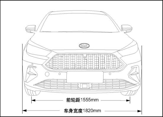
Front view
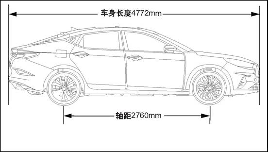
Side view
Rear view

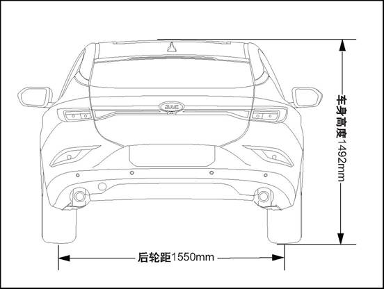
(1) Vehicle dimensional
specifications
|
Item
|
Parameters
value
|
Unit
|
|
Total
length
|
4772
|
mm
|
|
Total
width
|
1820
|
mm
|
|
Total height
(empty load)
|
1492
|
mm
|
|
Wheelbase
|
2760
|
mm
|
|
Front
tread
|
1555
|
mm
|
|
Rear
tread
|
1550
|
mm
|
(2) Maintenance parameters 1-15
|
Item
|
1.5T+6MT
|
1.5T+CVT
|
Unit
|
|
passengers
|
5
|
5
|
Man
|
|
Curb weight
|
1432
|
1440
|
Kg
|
|
Maximum weight
|
1857
|
1865
|
Kg
|
|
Front axle’s load
|
967
|
977
|
Kg
|
|
Rear axle’s load
|
890
|
888
|
Kg
|
9.
Vehicle identification
(1)
Vehicle identification code
Vehicle
identification number
Vehicle
VIN is a legal identifier.
Vehicle
identification number (VIN) position
There
are several vehicle identification codes on the vehicle,and the following 10
are the most common:
1.
Located on the dashboard in the lower left corner of the windshield, VIN can be
seen through the windscreen.
2.
Under the front passenger seat.
3.
In the vehicle glove box.
4.
On the engine cover.
5.
Located in front of the front right door.
6.
Lower side of left B-column
7.
On the front of the left front door inner plate
8.
On the upper side of tailgate inner panel
9.
Refer to ECU data.
10.Refer
to MP5 data.
(2) Label
 Vehicle certification
 Tire information sign
The
tire pressure label is attached to the driver's door side and the tire size and
cold inflation pressure can be seen on the label. The recommended cold
inflation pressure indicated on this label is the minimum tire pressure
required to support the vehicle's maximum load capacity.
10.
Noise, vibration and abnormal sound
(1) Diagnostic information and
process
Wind noise / air
sound
△
Warning Refer to drive shaft "Warnings about vehicle assistant
driving" in the "Warnings and Precautions".
△
Caution
When the
technician checks the repaired fault location, the assistant should drive the
vehicle. Otherwise, it may cause injuries.
You
must test the car in the car, in order to accurately confirm the location of
the wind noise. In general, wind noise has major and minor leaks. If all leaks
are not repaired during the repair, wind noise can only be reduced and wind
noise can not be completely eliminated. Test-drive maintenance staff must bring
the following tools to help diagnose the specific location of wind noise:
Stethoscope
Masking
tape
Stitch
seam
Marker
pen
screwdriver
Follow the procedure below to carry
out road test:
Select
a line, with east, south, west and north four different directions of the
straight street.
Choose
less traffic or less noise in the street, to avoid affecting the test.
The road test is conducted at the
speed at which the customer believes the noise is most pronounced or noisy, and
a speed limit of more than the legal limit is strictly prohibited.
The wind noise emitted under the
following conditions is external wind noise:
Wind
noise can be heard immediately while driving down the window glass.
When the tape is attached to the
various decorative seals and gaps, the wind noise disappears immediately.
Internal wind noise is caused by
air escaping from the vehicle and should be repaired as follows:
In
determining the location of the leak, attach the tape to the body lock pillar
relief valve. The air pressure will be formed immediately inside the car, and
the wind noise will be enhanced.
Use
a stethoscope to confirm the leak location.
Use
masking tape to temporarily repair leaks.
Continue
road test to confirm whether the wind noise is completely eliminated or other
leaked parts.
After
confirming all leaks by road test, return to the repair shop and make permanent
repairs with professional and reasonable positioning methods and sealing
materials.
Vibration
Most
of the high-speed vibration is due to the loss of dynamic balance of the wheel,
if there is still vibration after the dynamic balance is:
Tire
deformation
Rim
deformation
Tire
hardness deviation
Measurement of tire and
wheel free run out, can not detect all the causes leading to vibration, the
above three reasons for the load radial run out, you must use well-known tire
and wheel assembly to replace the original tire and wheel assembly, To carry
out maintenance on the faulty vehicle.
Low-speed vibration that occurs at
speeds below 64 km / h is usually caused by jerkiness. High-speed vibration at
speeds above 64km / h is usually caused by unbalance or run out.
Correct inhomogeneous
tires
There
are usually two ways to correct tires that are properly balanced but still
vibrate. One way is to use an automatic machine to attach the tire to the
machine and to rub a small amount of rubber from the high point on the pattern
on the left and right of the tire. Tire calibration using this method is usually
permanent. If this is done, there is no noticeable effect on the appearance of
the tire and on the life of the tire tread. It is not advisable to use a bladed
machine tool to correct the tire when calibrating the tire as this will shorten
the service life of the tire and will not fundamentally solve the problem.
Another way is to disassemble the
tire and turn the tire 180 ° on the rim. This method should only be used if it
is confirmed after diagnosis that the tire and wheel assembly are causing
vibrations. This is because this method is equally likely to cause vibration of
the intact wheel assembly.
Abnormal sound
When
the engine speed is high, the car makes a squeaky check if the insulation panel
touches the bottom of the car body.
Lift
the vehicle and perform a visual inspection
Bend
the insulation panel slightly to create a gap between it and the bottom of the
vehicle body.
The front of the
vehicle squeaks when the weather is cold
Check
the balance bar isolation rubber sleeve
Cold
Road Test vehicle and pass the bumpy road, so that the front suspension can
reach maximum travel.
Remove
the isolation rubber sleeve and tape the front stabilizer bar, reinstall the
isolation rubber sleeve on the tape.
Bumpy rear bass
issued by the boring abnormal sound
Check
if the spare tire in the luggage compartment is properly secured
Open
the luggage compartment and inspect the spare tire and driver's tools.
Re-tighten
spare tires and truck tools.
Test
vehicle to check whether abnormal sound has been eliminated.
The rear of the
vehicle emits a glass percussion while traveling on a bumpy road
Check
the rear door lock is not properly adjusted
Road
test vehicle to check this situation.
Loosen
the lock nut and adjust the lock.
The door squeaked
Check
if the harness connector inside the door trim panel creaks
Tap
the trim plate and pay attention if you hear a squawk
Remove
the door trim and wrap the foam padding around the harness connector according
to the actual vehicle conditions.
Squeaking when using
the door
Check
door hinges for lack of lubrication.
Push
the door back and forth and listen carefully to check whether the door squeaks.
Use
rust inhibitor to lubricate the door hinge and apply grease.
A manual transmission
squeaks when shifting gears (when the weather is cold and appears in a cold
state)
Check
manual gearbox lower shifter assembly
Switch
the shift lever between the stops and see if any squeaks appear.
Remove
floor console and replace shift lever lower boot or lower boot with talc.
(2)
Maintenance guide
Wind noise / air
sound
External wind noise
Repair methods of wind noise
leakage and water leakage are similar, refer to he diagnostic information and
procedures. The actual repair procedure depends on the type of sealing
components being repaired.
Vibration
Wheel and tire
balance on the car
Keep
wheel balance with E-car balancing machine Balancing machine is easy to use,
both for static balance, but also for dynamic balance. The difference between
balance on the car and balance under the care is that the imbalance of brake
disc can not be corrected under the car. However, the accuracy of the
under-ride balance overcomes this disadvantage by securing the wheel to the
balancing machine so that a cone passes through the back of the center hole
without passing through the wheel nut bore.
Wheel and tire
balance under the car
On-board
balance corrects vibrations due to disc brake imbalance.Wheel and tire balance
on the car
△
Warning Lower support arms are supported in a normal horizontal position to
avoid damaging the trans-axle. When the wheel sink to reach the full stroke, do
not hang up the operation of the vehicle.
It
is forbidden to disassemble the balance weight that the wheel installs when the
car is under dynamic balance when carrying out dynamic balance operation on the
car.
If
you need to add more than 25g when balancing, then divide the balance into two
pieces, install them on inner and outer rims respectively.
Spin
the driven wheel and wheel assembly with the engine.
Wheel
and tire orientation with the assembly
Wheels
and tires are factory fitted and fitted to match the thicker part of the tire
(also known as the high point) to the minimum radius of the wheel, also known
as the low point. At the very beginning of the tire factory, the high point of
the tire was initially marked with a red paint mark or affixed to the outer
wall of the tire.
Wheel
low for the valve core position.
Before
removing the tire from the wheel, make a mark on the tire valve core position
to ensure that it can be installed to its original position. Before removing
the tire from the wheel,
make
a mark on the tire valve core position to ensure that it can be installed to
its original position.
Abnormal sound
Repair of abnormal
sound
Abnormal
sound comes mainly from the relative motion that should not exist between the
vehicle parts. There are three ways to repair abnormal sound:
Firmly
tighten the parts so that there is no relative movement of the vehicle during
driving.
Separate
parts so that parts do not come into contact with them at work.
Isolate
parts so that there is no abnormal noise when parts move. A uniform surface
with low-friction can be used to eliminate sticking slip between parts.
11.
Tool purchasing channel and diagnosis device
△Note:
If you want to buy special tool, please contact 4S shop in each area of JAC.
For contact information, please contact 4008889933.
|
No.
|
Diagnosis device type
|
Diagnosis device version
|
Tool
No.
|
|
1
|
3G-X431
|
V11.70
|
JAC-T1Z002
|
Clutch and control system
I Overview
(1) Structure Outline
structure outline
The clutch
assembly is located between the engine and the transmission. The clutch
pressure plate assembly is fixed on the rear plane of the flywheel by a bolt.
The clutch driven disk is connected with the input shaft of the transmission
through a spline so as to slide axially and transmit torque in the
circumferential direction . As the car travels, the driver can disengage and
gradually engage the engine and transmission to cut off or transmit engine
input power to the transmission as the driver steps on or off the clutch pedal.
The
clutch system mainly includes the following components:
Active: Clutch pressure plate
assembly
Clutch pressure plate assembly
bolted to the flywheel.
Follower: clutch driven disk
The
clutch driven plate is splined to the transmission input shaft. Active parts
and followers by spring pressure to maintain contact. The pressure is applied
by the diaphragm spring in the platen assembly.
Control:
Clutch control system includes clutch pedal, master cylinder, tubing, and
release bearings
Clutch pressure plate, clutch driven plate structure
drawing

1.Rear shock absorber
2.
Disassemble clutch hose assembly
3.
Main cylinder oil outlet hard pipe assembly
4.
Clutch main cylinder and oil inlet pipe assembly
5.
Clutch housing
6.
Clutch pressure plate assembly and driven plate
7.
Hydraulic separating bearing
Clutch pressure
plate, clutch driven plate structure drawing

1.
Clutch cover & pressure plate assy.
2.
clutch driven disk
3.
Hexagon bolt, spring washer and flat washer assembly
Clutch main cylinder

1.
Air Inlet Pipe
2
cylinders
3.
Sensor
4.
Shaft pin
5.
gasket
6.
Split pin
(2) Maintenance
parameters
Maintenance
parameters
|
No.
|
Item
|
Parameter
|
|
1
|
clutch
free travel stroke
|
6~20mm
|
Lubricating
Grease
|
No.
|
Item
|
Brand
|
|
1
|
Master
cylinder master pin
|
Kunlun No.2 low temperature lubricating
grease
|
(3) Torque parameter
|
No.
|
Item
|
Torque
(N·m)
|
|
1
|
Clutch pull cable bracket fixing bolt
|
18~22
|
|
2
|
Clutch main cylinder
and oil inlet pipe assembly
|
18~22
|
|
3
|
Main cylinder oil outlet hard pipe
assembly
|
20~28
|
|
4
|
The clutch pedal and the main clutch
pump and intake pipe installation
|
20~28
|
|
5
|
Clutch pedal fixing bolt
|
20~28
|
|
6
|
Clutch pressure plate mounting bolt
|
20~28
|
|
7
|
Main cylinder oil outlet hard pipe
assembly
|
18~22
|
(4) Special tools
|
No.
|
Tool No.
|
Tools
|
Outside
View
|
Description
|
|
1
|
JAC-T1F011
|
Flywheel stop
|

|
Fixed flywheel
|
△Note:
If you want to buy special tool, please contact 4S shop in each area of JAC.
For contact information, please contact 4008889933.
(5).
Maintenance precautions
Cautions
The
recommended clutch hydraulic oil is the brake fluid "DOT 4".
•
Do not reuse the discharged clutch hydraulic oil.
•
Be careful not to spill the clutch hydraulic oil onto the body finish.
Do
not use mineral oil such as gasoline or kerosene, otherwise it will corrode the
rubber parts in the hydraulic system.
Please
don’t disassemble master cylinder and slave cylinder.
△
Warning Clean the clutch brake pad. Please use a vacuum cleaner, do not use
compressed air cleaning.
Maintenance
points
△ NOTICE Do not operate the system
using a vacuum pump or any other type of emptying power unit.
Check the liquid level of the
clutch hydraulic oil. Make sure the level is normal.
Do not let the clutch hydraulic oil
fall on the body paint or other parts. If the clutch hydraulic oil splashed on
the body paint or other parts, immediately wipe with a dry cloth.
Ⅱ Troubleshooting
(1)
common fault diagnosis
Clutch
assembly and clutch control system performance diagnostics should be performed
by an experienced driver or a skilled automotive service technician.
The following (trouble) diagnoses
involve common problems and possible causes. After making appropriate
diagnoses, make adjustments according to the appropriate solutions in the
diagnostic tables and the appropriate chapter for each specific procedure in
the service manual, or replace the parts as required.
During vehicle service, the clutch
plate and the clutch plate can not be repaired. If any one of them is broken,
replace the entire assembly.
If
the clutch driven plate rivets wear or clutch driven disk by the oil or grease
dirty, you can no longer use the clutch plate. If you need to change a part,
use a new, quality part to replace it. This diagnostic table helps to diagnose
malfunctions of the clutch system caused by the following conditions: Inability
to separate, incomplete separation, incomplete engagement, slipping, noise,
jitter.
Shake
The
numbers in this diagnostic table do not imply the order of examinations, and
there is no prior relationship between the various possible causes.
(2) fault diagnosis table
|
No.
|
Fault symptoms
|
Fault analysis
|
Solutions
|
Remark
|
|
1
|
Can not be separated
|
Failure to disengage means that the
clutch cannot function and cannot cut off the power transmitted from the
engine.
Failure to
disengage means that the clutch cannot function and cannot cut off the power
transmitted from the engine.
Check the following
conditions:
1. Clutch release
lever deformation.
2. Film spring
deformation.
3. Diaphragm
spring support ring fracture.
4. Clutch brake
pad is bonding with flywheel or clutch pressure plate
|
Replace parts
those has deformation, wear,
fracture
Adjust the clutch
system.
|
|
|
2
|
Incomplete
separation
|
A half-way clutch separation will cause
abnormal cut-off
The power
transmitted from engine. The transmission rod will be difficult to operate
since the the clutch friction plate and transmission input shaft are keep
rotating.
Check the
following conditions:
1. When clutch
brake pad has deformation,it will swing under rotating
2. Clutch brake
pad damage.
3. The spline of
clutch brake pad does not match with the input axis of the transmission,or
the spline surface is damaged
4. Clutch brake
pad is bonding with flywheel or clutch pressure plate
Clutch pressure
plate
5. Flywheel/
clutch pressure plate/ clutch brake pad thickness exceed regulated size.
|
Replace parts those has deformation、wear、fracture and sizes out
of regulation If the clutch brake pad does not work well with the
transmission input axis spline,replace the pad,even replace the input axis if
it is necessary. If the clutch brake pad exceeds the specified size or is
damaged, replace it. Replace the clutch thrust bearing that does not apply.
Adjust clutch system to remove unnecessary clearance and eliminate mechanical
failure. Reinstall the unbefitting parts.
|
|
|
3
|
Incomplete joint
|
A half-way clutch separation will make
engine unable to transmit engine power to
transmission’s input shaft, and the clutch friction plate will slip
Clutch brake pad
Check the following conditions:
1. Clutch brake pad is contaminated with
oil or grease.
2. Clutch brake
pad damage.
3. Clutch pedal
has no free travel.
4. Film spring/clutch pressure plate/clutch
release lever/Clutch brake pad
spline damage or wear
|
Replace parts those has
deformation, wear, fracture. Replace clutch brake pad or replace the abnormal
clutch assembly Adjust the clutch pedal free travel correctly. Adjust clutch
system to remove unnecessary clearance and eliminate mechanical failure.
Reinstall the unbefitting parts.
|
|
|
4
|
Slipping
|
The slipping of the clutch friction
plate can cause the engine to fail to transfer power properly.
Power
Check the
following conditions:
1. Clutch brake
pad wear.
2. Clutch brake
pad is contaminated with oil or grease.
3. Clutch
Incomplete joint.
4. Flywheel/
clutch pressure plate/ clutch brake pad thickness exceed regulated size. The
friction surface has exceeded set specification.
5. Excessive high
temperature in the clutch housing caused by improper driving too high
6. Installed the
poorly assembled clutch.
|
Replace parts
those has deformation, wear,
fracture
and sizes out of regulation.
The solutions of
“ incomplete release” and “ Incomplete joint ”.
The solutions of
“ incomplete release” and “ Incomplete joint ”.
shut off the
engine and cool down the temperature inside clutch’s outer housing, then make
further diagnosis.
Temperature is
too high.
Install the
specified clutch.
Reinstall the
unbefitting parts.
Do not place your
feet on the clutch pedal while driving.
|
|
|
5
|
Noise
|
Check the following conditions:
1. Poorly assembled
clutch brake pad.
2. Poor balance.
3. Clutch thrust
bearing malfunction.
4. Clutch brake
pad torsional damping spring is damaged.
|
Replace parts those has deformation,
wear, fracture.
Install specified
clutch brake pad.
If there is poor
balance part,replace the clutch assembly
Brake Assembly
Reinstall the
unbefitting parts.
|
|
|
6
|
Jitter
|
This occurs when the clutch brake pad is
unable to engage the flywheel gently.
Check the
following conditions:
1. Clutch brake
pad damping spring does not meet specifications.
2. Clutch brake
pad does not meet specifications.
3. Clutch brake
pad is contaminated with oil or grease.
|
Replace clutch
assembly
|
|
III.
clutch pedal free travel adjustment
(1) Special tool (none)
(2)
Adjustment
 1. Adjust the clutch pedal free
travel
1. Adjust the clutch pedal free
travel
1) Slide the clutch pedal to the
end and measure the clutch pedal stroke at the start position to the end
position
2) Loosen the lock nut and turn the
bolt to adjust the clutch pedal stroke. Tighten the lock nut after adjustment.
△
CAUTION When adjusting the clutch pedal height, do not push the push rod to the
clutch master cylinder.
Clutch
master cylinder
 3) Handle the clutch pedal by hand to determine when
the pedal has a resistance. The clutch pedal has a free stroke
3) Handle the clutch pedal by hand to determine when
the pedal has a resistance. The clutch pedal has a free stroke
Standard
size 6 ~ 20mm
4) Loosen the lock nut and turn the
fader, adjust the clutch pedal free travel, adjust the tightening lock nut
5)
Clutch pedal free travel should be within the standard value.
△
CAUTION If the free stroke of the clutch pedal is out of the specified range,
there must be air in the clutch hydraulic line or the master cylinder has a
fault.
.
. Please
exhaust the air inside system and dismantle and check master cylinder or
clutch.
IV. the hydraulic clutch exhaust
(1)
Special tool (none)
(2)
exhaust operation steps
△ Note: The system should be vented
when removing the clutch line, the clutch master cylinder, the clutch slave
cylinder and the clutch, the clutch pedal is soft, please discharge air in the
system.
 1.
Exhaust the air in the pipeline
1.
Exhaust the air in the pipeline
Loosen
the exhaust plug of the clutch slave cylinder.
2).
Slowly depress the clutch pedal until the air is completely discharged.
3).
Tighten the pedal completely and hold, tighten the exhaust bolts.
4)
Fill the hydraulic fluid of the clutch hydraulic system.
△
CAUTION Always keep the liquid level in the reservoir between MIN and MAX.
5) Repeat the above steps until the
system discharges the clutch hydraulic oil clean and does not contain air
bubbles.
2.
Make sure the clutch is working properly.
1) Start the engine, depress the
clutch pedal, after about 2s carefully into the reverse gear. If there is more
noise in the selection, fully apply the clutch pedal 5 times to vent the
system.
2)
Wait for about 30s, then check the clutch work. If there is still loud noise,
repeat the exhaust.
V.
Clutch main cylinder and oil inlet pipe assembly
(1)
Special tool (none)
(2) Disassembly
1.
Open the engine cover
2.
Clutch main cylinder and oil inlet pipe assembly
1)
release clutch hydraulic oil from clutch air outlet valve. During dismantling
process, press and hold clutch pedal and prevent the hydraulic oil from
leaking.
 2). Disconnect the shaft pin, washer and split pin
between clutch main cylinder and oil-inlet rod and clutch pedal
2). Disconnect the shaft pin, washer and split pin
between clutch main cylinder and oil-inlet rod and clutch pedal
 3). Disconnect the
2 connecting nuts which connects clutch pedal and clutch master cyliner and
oil-inlet pipe
3). Disconnect the
2 connecting nuts which connects clutch pedal and clutch master cyliner and
oil-inlet pipe
 4). Disconnect the
fixing bolt of main cylinder tube and bodywork
4). Disconnect the
fixing bolt of main cylinder tube and bodywork
 5). Disconnect the connecting nut of main cylinder
pipe and clutch amin cylinder and oil-inlet pipe. Then disconnect the pipe.
5). Disconnect the connecting nut of main cylinder
pipe and clutch amin cylinder and oil-inlet pipe. Then disconnect the pipe.
6). Dismantle the fixing clamp ring, then disconnect
the connecting hose of clutch main cylinder and oil-inlet assy and brake oil
kettle.
 7). Disconnect the clock spring
wire harness connector.
7). Disconnect the clock spring
wire harness connector.
8)
Clutch main cylinder and oil inlet pipe assembly
(3)
Inspection
1.
Check the clutch line
1).
Check clutch line for blockage.
2)Check
clutch hose and tube for damage or rust damage.
(4)
Installation
1.
Clutch main cylinder and oil inlet pipe assembly
△Note:
Apply specified hydraulic fluid (brake hydraulic fluid DOT4) to the outside of
cylinder body wall and piston assembly.
1). Move the clutch main cylinder
and oil-inlet pupe to assembly position, then connect harness connector
2). Connect the hose which connects clutch main
cylinder and oil-inlet pipe and brake oil kettle, then assemble.
clamp
 3). Tighten the connecting nut and connect the main
cylinder oil-outlet pipe and clutch main cylinder and oil-inlet pipe.
3). Tighten the connecting nut and connect the main
cylinder oil-outlet pipe and clutch main cylinder and oil-inlet pipe.
.
Tightening
torque 18~22N·m
 4) assemble the fixing bolt of main
cylinder oil-outlet pipe and bodywork
4) assemble the fixing bolt of main
cylinder oil-outlet pipe and bodywork
Tightening
torque 20~28N·m
 5) assemble the two fixing nuts of
clutch pedal and clutch main cylinder and oil-inlet pipe
5) assemble the two fixing nuts of
clutch pedal and clutch main cylinder and oil-inlet pipe
Tighten
torque 20~28N·m
 6) assemble the shaft pin, washer and split pin of
clutch main cylinder and oil-inlet pipe rod and clutch pedal
6) assemble the shaft pin, washer and split pin of
clutch main cylinder and oil-inlet pipe rod and clutch pedal
2.
Fill the clutch hydraulic fluid, and exhaust
3.
Close the engine compartment cover
VI. Clutch pedal
(1)
Special tool (none)
(2) Disassembly
1.
Remove the clutch pedal
 1). Disassemble the split pin, washer, take out the
pin shaft and disconnect the connecting joint between the locking piece and rod
1). Disassemble the split pin, washer, take out the
pin shaft and disconnect the connecting joint between the locking piece and rod
.
 2) dismantle the 2 fixing nuts and
1 fixing bolt of clutch pedal
2) dismantle the 2 fixing nuts and
1 fixing bolt of clutch pedal
3)
Remove the clutch pedal.
(3)
Inspection
1.
Check the clutch pedal
1).
Check clutch pedal for distortion, damage or cracked weld.
If this happens above, replace the pedal assembly.
(4) Installation
1.
Install the clutch pedal
 1) assemble clutch pedal, tighten the 2 fixing nuts
and 1 fixing bolt of clutch pedal
1) assemble clutch pedal, tighten the 2 fixing nuts
and 1 fixing bolt of clutch pedal
Tightening
torque 20~28N·m
 2) assemble the shaft pin, washer and split pin of
clutch main cylinder and oil-inlet pipe rod and clutch pedal
2) assemble the shaft pin, washer and split pin of
clutch main cylinder and oil-inlet pipe rod and clutch pedal
△Note: Lubricating grease must be
applied to the outer surface of the shaft before installing the pin shaft
(Lubricating grease type is Kunlun No.2 low temperature lubricating grease).
When
adjusting the clutch pedal height, do not push the push rod to the clutch
master cylinder.
After
adjustment, check whether the clutch pedal travel and free travel in the
specified range.
.
After adjustment, check whether the
clutch pedal travel and free travel in the specified range.
If the free stroke of the clutch
pedal is out of the specified range, there must be air in the clutch hydraulic
line or the master cylinder has a fault.
. Should be system exhaust,
dismantling check the master cylinder or clutch.
controller.
Adjust
the clutch pedal free travel
VII.
Clutch pressure plate assembly and driven plate
(1) Special tools
|
No.
|
No.
|
Tools
|
Outside
View
|
Description
|
|
1
|
JAC-T1F011
|
Flywheel stop
|
|
Fixed flywheel
|
△Note:
If you want to buy special tool, please contact 4S shop in each area of JAC.
For contact information, please contact 4008889933.
(2)
Disassembly
1.
Open the engine cover
2.
Disconnect the negative harness of the battery refer to the disconnection and
connection of the battery
3.
Remove manual transmission assembly Refer to drive shaft Transmission Assembly
4.
Remove clutch pressure plate assembly
△Caution don’t make grease contact the friction plate, press
plate or flywheel’s surface
1)
Fix the flywheel with the flywheel stopper.
2) Loosen the 6 fixing bolts of clutch pressure plate
evenly, and then remove the clutch pressure palte assembly and driven plate.
△ CAUTION Only loosen one to two
turns per bolt at a time to avoid damaging the clutch housing flange.
3)
Remove the flywheel fixing bolt from the rear end of the cylinder block and
take down the flywheel.
(3)
Inspection
1.
Check clutch brake pad
1).
Check whether the surface has rivet loose, single surface contact and burn,
which can lead to deterioration and grease, etc. If any, please replace clutch
brake pad.
2)
Measure the sink depth of the rivet. If it exceeds the limit value, please
replace the clutch brake pad.
△Note:
sink depth limit value: 0.3mm.
3)
Check whether the return spring is loose or broken. If any, please replace the
clutch brake pad.
4) Load the clutch brake pad to the
input shaft, check the sliding state and the rotation direction loosen . If
sliding state is bad, it should be cleaned, after assembling it is still undesirable,
please change. If the loose is obvious, replace the clutch brake pad or input
shaft, or both.
2.
Check clutch pressure plate
1)
Check whether the end of the diaphragm spring is worn or not, whether there is
height difference or not. If there is any obvious wear or height difference
exceeding the limit value, the clutch brake pad needs to be replaced.
Abrasion
limit: 0.7mm
2)
Check the surface of the pressure plate for wear, whether it is cracked or
discolored.
3).
Check whether the rivet is loose and replace the clutch pressure plate if it is
loose.
3.
Check release bearing
1)
Check if there is burn, damage, abnormal noise or uneven rotation in the
bearing.
2)
Check if there is damage in diaphragm spring, if any, please replace.
4.
Flywheel
 1) Use micrometer measure the flatness of the contact
surface between the flywheel and the clutch brake pad.
1) Use micrometer measure the flatness of the contact
surface between the flywheel and the clutch brake pad.
Please replace flywheel if it is
not suitable.
2). If there is any ablation or
discoloration between the clutch pressure plate and the clutch brake pad
contact surface, please use sandpaper for repair.
△Note: Planeness can be measured on
the outer surface of the flywheel (not on the fixing pin).
(4)
Installation
1.
Clean and lubricate
1)
Clean the clutch driven disc and input shaft key-way to remove grease and wear
metal shavings.
2)
Apply grease to the input shaft key-way.
△ Note Recommended grease: SAE J310
or similar.
Make
sure that the grease is applied in the correct position as this may cause
noise, clutter, or damage to the clutch. Excess fat can also cause slippage or
jitter.
2.
Install clutch pressure plate assembly
1). Using special tools, locate the
clutch driven plate and the clutch plate.
 2) Follow the steps 1-2-3-4-5-6 as shown in the figure
to execute step by step. Tighten the clutch fixing bolts one by one.
2) Follow the steps 1-2-3-4-5-6 as shown in the figure
to execute step by step. Tighten the clutch fixing bolts one by one.
△ Note that each bolt 1 to 2 turns
gradually tighten the order. Tightening torque 20~28N·m
3)
Flywheel stop
3.
Install the manual transmission assembly.
4.
Connect the battery negative cable.
5.
Close the engine compartment cover
VIII. Main cylinder oil outlet hard
pipe assembly
(1)
Special tool (none)
(2) Disassembly
1.
Open the engine cover
2.
Main cylinder oil outlet hard pipe assembly
1)
Loosen the vent screw and drain the clutch fluid.
△Note: Do not let the clutch hydraulic
oil fall on the body paint or other parts. If the clutch hydraulic oil splashed
on the body paint or other parts, immediately wipe with a dry cloth and clean
with clear water.
.
 2) fixing bolt of main cylinder oil
outlet hard pipe assembly
2) fixing bolt of main cylinder oil
outlet hard pipe assembly
3) pull out the clamp plate and disconnect the connection
of clutch rigid pipe II and clutch hose assembly.
 4) Loosen the nut, and disconnect the connection of
clutch rigid pipe II and clutch hose assembly. Take off the oil-outlet pipe on
main cylinder.
4) Loosen the nut, and disconnect the connection of
clutch rigid pipe II and clutch hose assembly. Take off the oil-outlet pipe on
main cylinder.
(3)
Installation
1.
Main cylinder oil outlet hard pipe assembly
 1) connect main cylinder and oil-inlet pipe and main
cylinder oil-outlet pipe, then tighten the nut.
1) connect main cylinder and oil-inlet pipe and main
cylinder oil-outlet pipe, then tighten the nut.
Tightening
torque 18~22N·m
△Note:
Please use the tubing wrench to tighten the oil tube connector.
2) connect main cylinder oil outlet pipe and clutch
hose, then tighten the connecting nut, and place the clamp plate into the
bracket and clutch pipe
Tightening
torque 18~22N·m
△Note:
Please use the tubing wrench to tighten the oil tube connector.
3). Install the 1 bolt that
connect the stopper and the vehicle body.
Tightening
torque 20~28N·m
4).
Fill washing liquid.
2.
Hydraulic clutch exhaust
3. Close the engine compartment
cover
IX. Clutch hose assembly
(1) Special tool (none)
(2) Disassembly
1.
Open the engine cover
2.
Disassemble clutch hose assembly
1)
Loosen the vent screw and drain the clutch fluid.
△Note: Do not let the clutch hydraulic
oil fall on the body paint or other parts. If the clutch hydraulic oil splashed
on the body paint or other parts, immediately wipe with a dry cloth and clean
with clear water.
.
2)
pull out clamp plate on clutch bracket, then separate clutch pipeline and
bracket
3)
Loosen the nut, and disconnect the connection of clutch rigid pipe II and
clutch hose assembly.
 4) pull out the connecting clamp ring between
vibration isolator, then disconnect clutch hose and isolator.
4) pull out the connecting clamp ring between
vibration isolator, then disconnect clutch hose and isolator.
5)
Take down clutch hose assembly.
(3)
Installation
1.
Install clutch hose assembly
1)
connect the isolator and clutch hose, then insert the clamp ring.
2)
connect the main cylinder oil-outlet pipe and clutch hose, then tighten the
fixing nut.
Tightening
torque 18~22N·m
Please
use the tubing wrench to tighten the oil tube connector.
3)
fix the clutch pipeline with bracket, then assemble the clamp plate
4.
Fill the clutch hydraulic fluid.
2. Hydraulic clutch exhaust
3.
Close the engine compartment cover
X. Vibration isolator (optional
device)
(1)
Special tool (none)
(2) Disassembly
1.
Open the engine cover
2.
Dismantle the thermostat
1)
Loosen the vent screw and drain the clutch fluid.
△Note: Do not let the clutch
hydraulic oil fall on the body paint or other parts. If the clutch hydraulic
oil splashed on the body paint or other parts, immediately wipe with a dry
cloth and clean with clear water.
.
2) pull out the connecting clamp ring between
vibration isolator, then disconnect clutch hose and isolator.
 3)
pull out the clamp ring between three-way valve and vibration isolator, then
take off the isolator.
3)
pull out the clamp ring between three-way valve and vibration isolator, then
take off the isolator.
(3)
Inspection
1.
Check whether leakage exists in connecting joint of isolator and whether seal
ring is intact. If abnormal leak exists, please replace isolator.
(4)
Installation
1.Rear
shock absorber
 1). Connect three-way valve and
isolator, then insert the clamp ring.
1). Connect three-way valve and
isolator, then insert the clamp ring.
2) connect the isolator and clutch
hose, then insert the clamp ring.
3).
Fill washing liquid.
2.
Hydraulic clutch exhaust
3.
Close the engine compartment cover
Front suspension and sub frame
I Overview
(1) Structure Outline
Front
suspension and sub frame

1.
Front sub-frame assembly
2.
Front transverse stabilizer bar pull rod
3.
Left lower swing arm assembly
4.
Front wheel hub assembly and front steering knuckle
5.Left-front mud guard
6.
Front sub-frame connecting bracket
7.
Front shock absorber assembly
8.
Front stabilizer bar mounting bracket
9.
Front transverse stabilizer bar sleeve
10.
Front shock absorber assembly
11.
Right-front brake disc mudguard
Front shock absorber
assembly structure
1.
Sprial ring
2.
Dust cover
3.
Front Shock Absorber
4.
Upper Support Assembly
5.
Dumper block
6.
Spiral Spring Lower Vibration Insulation Pad
7.
Spiral spring upper tray
Front hub assembly
structure
1.
Left front hub bearing unit
2.Left-front Mud guard
3.Steering knuckle
4.
Right front hub bearing unit
5.
Right-front Mud guard
6.Steering knuckle
(2)
Technical Parameters
|
Item
|
Parameters
and specifications
|
|
Front
Suspension Type
|
McPherson
independent suspension with spiral spring
|
|
Shock Absorber
|
Items
|
Two-way
hydraulic cylinder
|
|
Stroke
|
>157.5mm
|
|
Damping Force
|
Stretch
|
572N±74N (0.3m/s)
|
|
Compression
|
253N±61N (0.3m/s)
|
|
Spiral
Spring
|
Free height: 365mm (Reference)
|
Color Tags: A white or a yellow
|
|
Front wheel
positioning (no load)
|
Wheel Beam (front)
|
5′±2.5′
|
|
Camber
Angle
|
15′±30′
|
|
Kingpin
caster angle
|
5°19′±30'
|
|
Kingpin
caster angle
|
12°99′±30′
|
|
Kingpin
Offset
|
>5.8mm
|
(3) Torque parameter
|
No.
|
Item
|
Tightening
torque (N · m)
|
|
1
|
Steering
gear and front sub frame connection bolts
|
95~105
|
|
2
|
Front
stabilizer bar fixing bracket
|
55~65
|
|
3
|
Remove
the fixed bolt between subframe and front body.
|
190~210
|
|
4
|
Tightening
bolt between steering tie rod and steering knuckle.
|
40~50
|
|
5
|
Transmission
universal joint bolt
|
30~35
|
|
6
|
Rear
fixed bolt of front subframe
|
3~5
|
|
7
|
Front
shock absorber installing nuts
|
45~55
|
|
8
|
Remove
the 3 fixing nuts of front shock absorber and vehicle body.
|
45~55
|
|
9
|
The
connecting bolt between front shock absorber and steering knuckle
|
130~150
|
|
10
|
Remove
the connecting nut of front transverse stabilizer bar and front shock
absorber assembly.
|
65~75
|
|
11
|
Remove
fixing bolts between the lower swing arm and the sub frame front connecting
point.
|
150-170
|
|
12
|
Tighten
the fixing bolt of lower swing arm and sub-frame rear connection point.
|
190~210
|
|
13
|
Tighten
1 fixing nut that connects the lower swing arm ball pin and the steering
knuckle.
|
80~90
|
|
14
|
Disassembly
Stabilizer Lever connecting ball head and front column assembly retaining
nut.
|
65~75
|
|
15
|
Front
sub-frame connecting bracket
|
190~210
|
|
16
|
Front
accessory frame and body connection tightening
|
55~65
|
|
17
|
Steering
rod and steering knuckle connected slotted nut
|
40~50
|
|
18
|
Fixing
bolt of front wheel speed sensor assembly and front steering knuckle
|
8~12
|
|
19
|
Front
brake caliper and knuckle connecting bolts
|
7
~
11
|
(4) Special tools
|
No.
|
Tool No.
|
Tool name
|
Outside
View
|
Usage
|
|
1
|
JAC-T1D003
|
Steering Drive
Rod Die
|

|
Remove the
steering ball
|
|
2
|
JAC-T1D004
|
Damper Spring
Remover
|

|
Remove and
install shock absorber
|
△Note:
If you want to buy special tool, please contact 4S shop in each area of JAC.
For contact information, please contact 4008889933.
(5).
Maintenance precautions
1.
The final tightening must be carried out under tire grounding and no-load
conditions when installing the suspension.
2.
After repairing the suspension parts, be sure to check the wheel alignment.
3.
The final tightening must be carried out under tire grounding and no-load
conditions when installing the rubber bushing.
4.
Oil will shorten the service life of rubber bushings. It is necessary to wipe
the spilled oil.
5.
No-load conditions are fuel, engine coolant and lubricants have been normal
filling, spare tires, jacks, vehicle tools and foot pad are in the specified
location.
6.
Locking nuts are not reusable. Always use the new bolt during installation.
Please do not wipe the anti-rust oil on the lock nut before tightening up the lock
nut during replacement.
(6) Inspection on vehicle
Confirm that whether the fixing
condition (clearance) and wear condition of each component are normal or not.
1. Check the tie rod clearance.
1).
Place front wheel straight forward.
2)
Place iron plate or similar tool between tie rod and steering knuckle.
3)
Pry up and down to check the clearance.
△Note:
Please don’t damage the ball joint dust cover.
Please don’t use too large force
casuing installation parts damaged.
2.
Check the damper
1).
Check if there is oil leaking, damage or cracking in the installation position.
(7)
Front wheel alignment inspection
1 System description
Check the wheel alignment when the
vehicle is in empty load state.
2)Pre-Check
Check
the following items:
1)
Check if the tire pressure is normal or if the tire have abnormal wear.
2)
check If wheel runout.
3)Wheel
bearing terminal clearance.
4)
Tie rod shaft terminal clearance.
5)
If every fastener of axle and suspension has looseness or deformation.
6)
Whether there is crack, deformation or other damage in each suspension
component, steering knuckle, shock absorber and tie rod.
7)
Vehicle body height.
(8) Check the front toe-in of the
front wheel
△Note that the wheels must be
positioned horizontally and at no load during adjusting. Front wheel toe-in
value: 5′±2.5′
 If the front wheel toe-in value is not within the
standard range, please adjust as following steps: 1. Check the setting of
toe-in value on the four-wheel aligner.
If the front wheel toe-in value is not within the
standard range, please adjust as following steps: 1. Check the setting of
toe-in value on the four-wheel aligner.
2.
Straighten and fix the steering wheel.
 3
Loosen the lock nut of tie rod end.
3
Loosen the lock nut of tie rod end.
4.
Turn the tie rod clockwise or counterclockwise to adjust the toe value to the
standard value.
△
Caution: the rotating amounts of tie rod are the same
5.
Lock the lock nut of tie rod end.
Tighten
torque 50 ~ 55N · m
(9) Inspection of kingpin caster
angle, kingpin inclination and caster angle
Front
camber:15′±30′
Kingpin
Caster Angle:4.6°±30′
Kingpin
Inclination Angle:13.4°±30′
△ Note: camber, caster angle and
kingpin inclination at the factory has been set, do not make adjustments.
If
the camber angle,kingpin caster angle and kingpin inclination angle are not within
the standard range, please check the front suspension,steering knuckle,shock
absorber and stabilizer for wear or damage. If any, please replace the
suspicious parts.
Ⅱ Troubleshooting
(1)
Troubleshooting table
|
No.
|
Fault symptoms
|
Fault analysis
|
Solutions
|
Remark
|
|
1
|
Hard Steering
|
Improper Front Wheel Alignment
|
Adjustment or replacement
|
|
|
Rotation surpasses the ball head of
lower suspension arm
|
Replacement
|
|
Lower Tire Pressure
|
Air Inflation
|
|
No Power Steering
|
Repair or Replacement
|
|
2
|
Bad Return
|
Improper Front Wheel Alignment
|
Adjustment
|
|
|
Shock Absorber Malfunction
|
Repair or Replacement
|
|
Anti-Roll Bar Wear or Damage
|
Replacement
|
|
Spiral Spring Wear or Damage
|
Replacement
|
|
Lower Suspension Arm Bushing Wear
|
Replacement
|
|
3
|
Abnormal Tire
Wear
|
Improper Front Wheel Alignment
|
Adjustment
|
|
|
Lower or Higher Tire Pressure
|
Pressure Adjustment
|
|
Shock Absorber Malfunction
|
Repair or Replacement
|
|
4
|
Vehicle Deviation
|
Improper Front Wheel Alignment
|
Adjustment
|
|
|
Insufficient Steering Resistance of
Lower Suspension Arm Ball Joint
|
Replacement
|
|
Lower Suspension Arm Bushing Looseness
or Wear
|
Replacement
|
|
5
|
One-Way Deviation
of the Vehicle
|
Improper Front Wheel Alignment
|
Adjustment
|
|
|
Insufficient Steering Resistance of
Lower Suspension Arm Ball Joint
|
Replacement
|
|
Lower Suspension Arm Bending
|
Replacement
|
|
Spiral Spring Wear or Damage
|
Replacement
|
|
6
|
Steering Wheel
Wobble
|
Improper Front Wheel Alignment
|
Adjustment
|
|
|
Insufficient Steering Resistance of
Lower Suspension Arm Ball Joint
|
Replacement
|
|
Lower Suspension Arm Bushing Looseness
or Wear
|
Replacement
|
|
Shock Absorber Malfunction
|
Repair or Replacement
|
|
Anti-Roll Bar Wear or Damage
|
Replacement
|
|
Spiral Spring Wear or Damage
|
Replacement
|
|
7
|
Vehicle Sagging
|
Spiral Spring Wear or Damage
|
Replacement
|
|
|
Shock Absorber Malfunction
|
Repair or Replacement
|
Front
Subframe Assembly
(1) Special tools
|
No.
|
Tool No.
|
Tool name
|
Outside
View
|
Usage
|
|
1
|
JAC-T1D003
|
Steering Drive
Rod Die
|
|
Remove the
steering ball
|
△Note:
If you want to buy special tool, please contact 4S shop in each area of JAC.
For contact information, please contact 4008889933.
(2)
Disassembly
1.
Lift up the vehicle.
2.
Remove front wheel. Refer to tire assembly
3.
Disassemble the crankshaft pulley with reference to crankshaft pully
4.
Remove deflector. Refer to deflector assembly
5.
Remove the front exhaust pipe assembly. Refer to the front exhaust pipe
assembly
6.
Remove the lower swing arm assembly , refer to the lower swing arm assembly
chapter.
7.
Remove front transverse stabilizer bar pull rod. Refer to front transverse
stabilizer bar.
8.
Remove the rear suspension assembly with reference to rear suspension assembly
9.
disassemble the rear suspension cushion and rear suspension bracket.
10.
disassemble the rear suspension cushion and rear suspension bracket.
11.
Disassemble the sub-frame with reference to the sub-frame
12.
Front sub-frame assembly
1) Top with the support of
sub-frame.
 2)
disassemble the 2 fixing bolts on front sub-frame and left&right wheel
cover
2)
disassemble the 2 fixing bolts on front sub-frame and left&right wheel
cover
 3)
disconnect the connecting bolt between steering device and universal joint
3)
disconnect the connecting bolt between steering device and universal joint
4) pull out opening pin and disassemble the 2
connecting nuts between steering device rod and left&right steering
knuckle. Use special tools to disconnect the connection.
5) disasemble the 2 fixing bolts on sub-frame and
left-front & right-front bodywork. Then disassemble sub-frame
Front stabilizer rod and steering
device.
6) Remove the 2 fixing bolts of left and right
stabilizer bar fixing bracket, and take down the mounting bracket and bushing.
.
7)
Remove the 2 bolt securing the steering device, then disassemble the device..
(3)
Inspection
1.
Check whether fracture exists on sub-frame
(4)
Installation
1.
Front sub-frame assembly
 1)
tighten the steering device to assembling position, then tighten the 2 fixing
bolts on steering device and front sub-frame
1)
tighten the steering device to assembling position, then tighten the 2 fixing
bolts on steering device and front sub-frame
.
Tightening
torque 95~105N·m
2)
move front stabilizer rod to assembling position, then tighten the two bolts on
the left&right bushing and bracket
.
Tightening
torque 55~65N·m
3)
assemble front sub-frame, then tighten the 2 fixing bolts on front syb-frame
and bodywork
Tightening
torque 190~210N·m
4)
connect steering rod and steering knuckle, then assemble the 2 fixing bolts on
rod and knuckle
Then
insert the split pin
Tightening
torque 40~50N·m
5) assemble the fixing bolt of
steering device and universal joint
Tightening
torque 30~35N·m
 6) assemble the 2
fixing bolts of front sub-frame and left&right wheel cover
6) assemble the 2
fixing bolts of front sub-frame and left&right wheel cover
1.Tightening
torque 3~5N·m
2.Front
sub-frame connecting bracket
3.Install
the rear suspension assembly connecting bracket
4.Rear
suspension connecting support
5.Install
rear suspension assembly
6.Install
the lower swing arm assembly
7.
Install the exhaust pipe assembly
8.Install
front transverse stabilizer bar pull rod
9.
Install the deflector assembly
10.
Install the front sill guard plate assembly
11.
Install front wheel cover
12.
Place down the car.
13.Check
wheel alignment Refer to drive shaft four-wheel alignment
IV. Front shock absorber assembly
(1) Special tools
|
No.
|
Tool No.
|
Tools
|
Outside
View
|
Description
|
|
1
|
JAC-T1D004
|
Damper Spring
Remover
|
|
Remove and
install the damper spring
|
(2) Disassembly
△ Note that left and right front shock absorber parts
and spring disassembly methods are similar.
1.
Lift up the vehicle.
2.
Remove front wheel. Refer to tire assembly
3.
Remove the vent cover assembly. See the “vent cover assembly”
4.
Remove front shock absorber assembly
1) disassemble clamp plate on brake hose, then
disconnect the hose and isolator.
2) Remove the connecting nut of front transverse
stabilizer bar and front shock absorber assembly.
3)
Remove the two connecting bolts of the steering knuckle and front shock
absorber.
4) Remove the 3 fixing nuts of
front shock absorber and vehicle body.
5)
Take out the shock absorber assembly
(3)
Decomposition
1. Disassemble
front shock absorber assembly
△Note:
Do not damage the shock absorber piston push rod when removing the shock
absorber parts.
 1)
Use a spring compressor to compress spiral spring until it separates
1)
Use a spring compressor to compress spiral spring until it separates
Note: Make sure the spring
compressor has been installed in place completely, then start to compress.
Do not use pneumatic wrench to
install bolts on spring compressor
2)
Fix the terminal of the damper piston bar and disassemble the lock nut of the
piston push rod.
Note:
Make sure the spiral spiral is loose after compressing.
3) Remove spiral spring upper
bracket, spiral spring upper vibration insulation pad, dust guard and dumper
block.
- Disassemble the spiral spring
with compressor , then loosen the compressor slowly.
4)
Disassemble spring lower vibration insulation pad and remove the shock absorber
body.
(4)
Inspection
1.
Check the damper
1)
Check if shock absorber has deformation, crack or damage. If any,please replace
it.
2)
Check the piston fader for damage, wear and deformation. If any,please replace
it.
3)
Check if piston leaks oil If any,please replace it.
2.
Check spring vibration insulation pad, damper block and dust guard
1).
Check if they have cracks and if the rubber parts have wear, ageing or other
damages. If any, please replace.
3
Check the spiral spring
1).
Inspect whether spiral spring is worn or damaged. If any, please replace.
4.
Check spiral spring upper bracket
1).
Check if it has cracks, wear, deformation and other damages. If any, please
replace.
5.
Check surface bearing
1).
Check if it has cracks, wear, deformation and other damages. If any, please
replace.
6.
Check upper support assembly
1).
Check if it has cracks, wear, deformation and other damages. If any, please
replace.
(5)
Assembly
1.
Assemble front shock absorber assembly
1) Use a spring compression tool to
compress the coil spring.
△
Note: spring larger, confirm the fixed firmly pay attention to safety. Confirm
Make
sure the stripping attachment has been installed on thread spring completely,
than start to compress the thread spring.
Spiral
Spring When loosen the stripping attachment, check if the installment position
of the thread spring is right.
Assembly
mark is correct.
 2)
In the shock absorber bracket, the installation of the front spiral spring
under the isolation pad, buffer block, dust cover, coil spring, coil spring on
the isolation pad, on the support, the front shock absorber on the bearing
assembly.
2)
In the shock absorber bracket, the installation of the front spiral spring
under the isolation pad, buffer block, dust cover, coil spring, coil spring on
the isolation pad, on the support, the front shock absorber on the bearing
assembly.
△Note: Do not damage the piston push
rod when mounting parts to the shock absorber.
Put
the big diameter end of sprial spring downward, and aim at the spring lower
bracket.
3)
Install the locknut and cover with the front dust cover on the front shock
absorber.
Tightening
torque 45~55N·m
△Note:
If the assembly mark is correct.
(6)
Installation
1.
Install front shock absorber assembly
1)
Tighten the 3 fixing nuts of front shock absorber assembly and vehicle body.
Tightening
torque 45~55N·m
△The final tightening of each of the
parts removed when the shock absorber is removed under no-load conditions.
Install front shock absorber assembly, and tighten the
two connecting bolts of front shock absorber assembly and steering knuckle.
Tightening
torque 130~150N·m
Tighten
the connecting nut of front transverse stabilizer bar and front shock absorber
assembly.
Tightening
torque 65~75N·m
Connect the brake hose, and install
the brake hose card.
Install
the vent cover assembly
3.
Install front wheel cover
4.
Place down the car.
Check
wheel alignment Refer to drive shaft four-wheel alignment
V. Lower
swing arm assembly
(1)
Special tools
|
No.
|
Tool No.
|
Tool name
|
Outside
View
|
Usage
|
|
1
|
JAC-T1D003
|
Steering Drive
Rod Die
|
|
Remove the
steering ball
|
(2) Disassembly
△Note
left and right rear brake disassembly method is similar.
1.
Lift up the vehicle.
2.
Remove front wheel. Refer to tire assembly
Remove
the lower arm assembly
1) Remove the nut of lower swing arm and steering
knuckle, and separate the connecting of the lower swing arm and the knuckle
joint using a special tool.
2)
Remove one fixing bolt from the connection point between the lower arm and sub
frame.
3) Remove the two fixing bolts of
the lower arm and the front connecting point of the sub frame.
4)
Remove the lower arm assembly.
(3)
Inspection
1.Check
the lower arm assembly.
2.Check
if the bushing is worn or damaged, replace if it is.
3.Check
the lower arm deformation or other damage, if any, please replace.
4.Check
the hem arm ball dust jacket for cracks, if any, please replace.
5.Check
all the fixing bolts and nuts for damage, if any, please replace.
(4)
Installation
1.Install
the lower swing arm assembly
1)
Install the lower arm assembly in the correct position.
Do
not use damaged parts. Pre-tighten the bolt of lower swing arm front rubber
sleeve and fixing bracket, and avoid the rubber sleeve twisted or deformed.
2)
Remove the two fixing bolts of the lower arm and the front connecting point of
the sub frame.
Tightening torque 150~170N·m
3)
Tighten the fixing bolt of lower swing arm and sub-frame rear connection point.
Tightening
torque 190~210N·m
4)
Tighten 1 fixing nut that connects the lower swing arm ball pin and the
steering knuckle.
Tightening
torque 80~90N·m
Caution Do not use damaged parts.
Pre-tighten
the bolt between the front rubber sleeve of lower suspension arm and fixed
support to avoid the distortion of rubber sleeve.
The
final tightening of each of the parts removed when the lower swing arm is
removed under no-load conditions.
2.
Install front wheel cover
3.
Place down the car.
4.
Check wheel alignment Refer to drive shaft four-wheel alignment
VI.
Front stabilizer bar assembly
(1)
Special tool (none)
(2) Disassembly
1.
Lift up the vehicle.
2.
Remove front wheel. Refer to tire assembly
3.
Disassemble the crankshaft pulley with reference to crankshaft pully
4.
Remove deflector. Refer to deflector assembly
5.Remove
the lower swing arm assembly , refer to the lower swing arm assembly chapter.
6.Remove
front transverse stabilizer bar pull rod. Refer to front transverse stabilizer
bar.
7.Remove
the rear suspension assembly with reference to rear suspension assembly
8.
disassemble the rear suspension cushion and rear suspension bracket.
9.
disassemble the rear suspension cushion and rear suspension bracket.
10.Disassemble
the sub-frame with reference to the sub-frame
11.Disassemble
the sub-frame assembly with reference to the sub-frame assembly
12.Remove
front stabilizer bar assembly
1) Remove the 2 fixing bolts of left and right
stabilizer bar fixing bracket, and take down the mounting bracket and bushing.
2)
Remove stabilizer bar assembly
(3)
Inspection
1.Check
front stabilizer bar assembly
1)
Check if the stabilizer bar, stabilizer bar pull rod assembly, stabilizer bar
fastening bracket and stabilizer bar bushings have deformation, wear or other
damages. If any,please replace it.
2)
Use your hand to move the ball studs to make sure they are flexible.
3)
Check whether the front stabilizer rod pull rod dust cover is broken and
whether there is grease leakage. If any,please replace it.
(4)
Installation
1.
Install the front stabilizer bar assembly
1)
Position the stabilizer bar assembly in the correct position.
2)
Install front stabilizer bar installation bracket and front transverse
stabilizer bar bushing, and tighten left and right
stabilizer fixing bracket 2 fixing
bolts.
Tightening
torque 55~65N·m
Caution: Pay attention to the
installation direction when installing the stabilizer bushing and stabilizer
holder.
Conduct
the final tightening of each component removed from the disassembled anti-roll
bar under no-load condition.
2.Front
sub-frame connecting bracket
3.Install
the rear suspension assembly connecting bracket
4.Rear
suspension connecting support
5.Install
rear suspension assembly
6.Install
the lower swing arm assembly
7.Install
front transverse stabilizer bar pull rod
8.
Install the deflector assembly
9
Install Belt
10.
Install front wheel cover
11.
Place down the car.
12.Check
wheel alignment Refer to drive shaft four-wheel alignment
VII.
Front transverse stabilizer bar sleeve
The
assembly and disassembly of front transverse stabilizer bar sleeve are similar
to those of front stabilizer bar. Please refer to “front stabilizer bar.
VIII.
Front stabilizer bar fixing bracket
The
assembly and disassembly of fixing bracket is similar to those of front
stabilizer bar. Please refer to “front stabilizer bar.
IX. Front transverse stabilizer bar
pull rod
(1)
Special tool (none)
(2) Disassembly
△
Note Left and right stabilizer bar disassembly method is similar.
1.
Lift up the vehicle.
2.
Remove front wheel. Refer to tire assembly
3.
Remove the front transverse stabilizer bar
1)
Remove the connecting nut of front transverse stabilizer bar and front shock
absorber assembly.
2) Remove the fixing nut of left and right transverse
stabilizer bar connecting ball head and front stabilizer bar assembly, and take
down front transverse stabilizer bar.
(3)
Installation
1.
Install front transverse stabilizer bar pull rod
1)
Position the front transverse stabilizer bar assembly in the correct position.
2)
Disassembly Stabilizer Lever connecting ball head and front column assembly
retaining nut.
Tightening
torque 65~75N·m
Caution Fix the stay bolt of
anti-roll bar tie rod first to avoid rotation when the lock nut is locked.
3)
Disassembly Stabilizer Lever connecting ball head and front column assembly
retaining nut.
Tightening
torque 65~75N·m
Caution Fix the stay bolt of
anti-roll bar tie rod first to avoid rotation when the lock nut is locked.
2.
Install front wheel cover
3.
Place down the car.
X. Front sub-frame connecting bracket
(1) Disassemble
1.
Lift up the vehicle.
2.
Front sub-frame connecting bracket
1)
Top with the support of sub-frame.
2) Disassemble the 2 bolts
connecting front sub-frame and bodywork
3)
disassemble the bolt that connects bracket and front sub-frame
4)
take off the connecting bracket
(2)
Installation
1.
Assemble the Front sub-frame connecting bracket
1) move the bracket to assembling postion, then
assemble the nut that connects bracket and sub-frame
Tightening
torque 190~210N·m
2)
assemble the 2 bolts connecting bracket and bodywork
Tightening torque 55~65N·m
2.
Place down the car.
XI. Front wheel hub assembly and
front steering knuckle
(1)
Special tools
|
No.
|
Tool No.
|
Tool name
|
Outside
View
|
Usage
|
|
1
|
JAC-T1D003
|
Steering Drive
Rod Die
|
|
Remove the
steering ball
|
(2) Disassembly
1.
Open the engine cover
2.
Disconnect the negative harness of the battery refer to the disconnection and
connection of the battery
3.lift
the vehicle
4.
Remove front wheel. Refer to tire assembly
5
disassemble the front brake caliper assembly, please refer to chapter “front
brake caliper assembly”.
6.
Disassemble brake disc assembly Refer to front brake disc
7.
Remove front mudguard. Please refer to left-front mudguard
8.
Remove front wheel hub assembly and front steering knuckle
 1) Remove the one fixing bolt connecting front wheel
speed sensor and front steering knuckle, then take out the sensor
1) Remove the one fixing bolt connecting front wheel
speed sensor and front steering knuckle, then take out the sensor
△ Caution: do not drag the wheel
speed sensor harness
2) Remove the nut of lower swing arm and steering
knuckle, and separate the connecting of the lower swing arm and the knuckle
joint using a special tool.
3) Remove the tightening nut connecting the steering
gear pull rod assembly and steering knuckle, and disconnect the connection of
steering gear pull rod assembly and steering knuckle.
4) Remove the
self-lock nut connected drive shaft to front wheel hub assembly.
 5) Remove the two
bolts and nuts connecting front shock absorber to steering knuckle
5) Remove the two
bolts and nuts connecting front shock absorber to steering knuckle
 6). Disconnect the drive shaft from
the hub assembly.
6). Disconnect the drive shaft from
the hub assembly.
7)
Take down front wheel hub assembly and front steering knuckle.
8) disassemble the 4 connecting bolts of front wheel
hub and front steering knuckle. Use special tool to separate front wheel hub
and front steering knuckle.
(3)
Inspection
1.
Check the wheel bearing
1)
Push wheel hub and bearing assembly in the axial direction by hands, and ensure
whether wheel bearing is loosened. If any,it is recommended to replace or
reassemble the bearing.
2)
Rotate wheel hub, ensure whether there is abnormal noise or other abnormal
condition. If any,it is recommended to replace the bearing.
(4)
Installation
1.
Install front wheel hub assembly and front steering knuckle
1) assemble the 4 bolts connecting front wheel hub and
front steering knuckle. Then connect the hub and knuckle.
Tightening
torque 90~110N·m
2)
Install the front hub assembly with the front knuckle onto the drive shaft.
△Note: Bearing oil seal should not
crack or damage phenomenon; the front hub unit shall not have cracks or other
defects; knuckle should not crack such defects.
.
After
the front wheel hub assembly is assembled, it can rotate normally, and the
shaft always moves back. There shouldn’t have the phenomenon of unsmooth or
moving axially.
.
 3)
Install the two bolts and nuts connecting front shock absorber to steering
knuckle
3)
Install the two bolts and nuts connecting front shock absorber to steering
knuckle
Tightening
torque 130~150N·m
4) Tighten the
self-lock nut connected drive shaft to front wheel hub assembly.
Tightening
torque 290~310N·m
5) Connect the
steering gear assembly and steering knuckle, and tighten the steering gear
assembly and steering knuckle connecting
.
Tightening
torque 40~50N·m
6) Tighten 1
fixing nut that connects the lower swing arm ball pin and the steering knuckle.
Tightening
torque 80~90N·m
 7)
Tighten the one fixing bolt connecting front wheel speed sensor and front
steering knuckle.
7)
Tighten the one fixing bolt connecting front wheel speed sensor and front
steering knuckle.
Tightening
torque 8~12N·m
△
Caution: do not drag the wheel speed sensor harness
2.
Install the front brake disc
3.
Assemble the front mudguard
4.
Install front brake caliper assembly
5.
Install front wheel cover
6.
Place down the car.
7.
Check wheel alignment Refer to drive shaft four-wheel alignment
8.
Connect the battery negative cable.
9.
Close the engine compartment cover
XII.
Left front mudguard
(1) Disassemble
1.
Lift up the vehicle.
2.
Remove front wheel. Refer to tire assembly
3
disassemble the front brake caliper assembly, please refer to chapter “front
brake caliper assembly”.
4.
Disassemble brake disc assembly Refer to front brake disc
5.
Remove the left front door cylinder
1) disassemble the 3 fixing bolts of left-front
mudguard and steering knuckle. Then take off left-front mudguard
(2)
Installation
1.
Install left front mudguard
1) move mudguard to assembling position, then assemble
the 3 fixing bolts of mudguard and steering knuckle
Tightening
torque 7~11N·m
2.
Install the front brake disc
3.
Install rear brake caliper assembly
4.
Install front wheel cover
5.
Place down the car.
Rear suspension
I
Overview
(1) Structure Outline
Rear
suspension structure

1.
Left trailing arm assembly
2.
Rear wheel hub and rear steering knuckle assembly
3.
Front lower pull bar assembly
4.
Rear pull rod assembly
5.
Rear stabilizing arm assembly
6.
Rear sliding column assembly
7.
Rear Stabilizer rod assembly
8.
Rear sub-frame assembly
9.
Rear the stabilizer bar rod
10.
Rear spiral spring
Rear sliding column
assembly

1.
Vibration Isolation Pressure Pad of Upper Mounting Plate
2.
Self-Locking Nut
3.
Dumper block
4.
Dust cover
5.
Rear sliding column assembly
(2)
Technical Parameters
|
Item
|
Parameters
and specifications
|
|
Rear
Suspension Form
|
Connecting
rod
|
|
Shock absorber
|
Items
|
Two-way
hydraulic cylinder
|
|
Stroke
|
175mm
|
|
Damping Force
|
Stretch
|
652N±85N (0.3m/s)
|
|
Compression
|
375N±58N (0.3m/s)
|
|
Spiral Spring
|
Items
|
Helical
Spring
|
|
Free
Height
|
331.8mm
(Reference)
|
|
Color
Mark
|
The
same color on both sides
|
|
wheel alignment
|
Wheel toe (single wheel)
|
4′±5′
|
|
Camber
Angle
|
-1°10′±30′
|
(3) Torque parameter
|
No.
|
Item
|
Tightening
torque (N · m)
|
|
1
|
stabilizer
fixing bracket 2 fixing bolts.
|
55~65
|
|
2
|
Front
fixed bolt of front subframe
|
170~190
|
|
3
|
Sub
frame rear fixing bolts
|
170~190
|
|
4
|
rear
shock absorber and body connection nut.
|
45~55
|
|
5
|
Rear
shock absorber and rear guide arm connecting bolts
|
120~140
|
|
6
|
Rear
suspension-arm assembly and rear stabilizer rod connecting bolt
|
65~75
|
|
7
|
Rear
vertical arm and vertical body-connecting bracket connecting bolt
|
100~120
|
|
8
|
Rear
suspension-arm assembly and sub-frame connecting bolt
|
100~120
|
|
9
|
The
connecting bolt between lower suspension arm ball pin and steering knuckle
|
130~150
|
|
10
|
The
connecting bolt between lower suspension arm ball pin and steering knuckle
|
100~120
|
|
11
|
The
connecting bolt between lower suspension arm ball pin and steering knuckle
|
100~120
|
|
12
|
The
connecting bolt between upper rod and rear sub-frame
|
100~120
|
|
13
|
The
connecting bolt between upper rod and rear steering knuckle
|
150-170
|
|
14
|
The
connecting bolt between lower rod and rear sub-frame
|
100~120
|
|
15
|
The
connecting bolt between lower rod and rear steering knuckle
|
100~120
|
|
16
|
Rear
brake and rear hub connecting bolts
|
7~11
|
|
17
|
Connecting
bolt of rear wheel hub and rear steering knuckle assembly
|
90~110
|
|
18
|
Connecting
nut of rear horizontal stabilizer and rear stabilizer rod
|
65~75
|
|
19
|
Rear
wheel speed sensor fixing bolts
|
8~12
|
(4)
Maintenance precautions
1.
The final tightening must be carried out under tire grounding and no-load
conditions when installing the suspension.
2.
After repairing the suspension parts, be sure to check the wheel alignment.
3.
The final tightening must be carried out under tire grounding and no-load
conditions when installing the rubber bushing.
4.
Oil will shorten the service life of rubber bushings. It is necessary to wipe
the spilled oil.
5.
No-load conditions are fuel, engine coolant and lubricants have been normal
filling, spare tires, jacks, vehicle tools and foot pad are in the specified
location.
6.
Locking nuts are not reusable. Always use the new bolt during installation.
Please do not wipe the anti-rust oil on the lock nut before tightening up the
lock nut during replacement.
(5) Inspection on vehicle
1.
Ensure fixed condition (loosenness, clearance) of each part and part condition
(abrasion, damage) normal.
Check
the installation position of shock absorber for oil leakage or damage.
Rear Wheel Alignment Inspection:
Caution After the relevant
components of rear suspension have been worn or changed,check whether the
location parameters of rear wheel meet the requirements or not.
rear
wheel single toe-in:4′±5
rear caster angle:-1°±30′
1 System description
Check the wheel alignment when the
vehicle is under no-load condition.
2)Pre-Check
Check
the following items:
1)
Check the tire pressure for standard value, check the tire for wear.
2)
check If wheel runout.
3)Wheel
bearing terminal clearance.
4)
Check each component clearance of suspension and each fixed point for
looseness.
5)
Check the shock absorber for maneuvering capability
6)
Check the cantilever for crack,deformation and other damage.
7)
Check the height of vehicle body.
Ⅲ Troubleshooting
(1) Troubleshooting table
|
No.
|
Fault symptoms
|
Fault analysis
|
Solutions
|
Remark
|
|
1
|
Abnormal sound
|
Loose assembly
|
Tightening
|
|
|
Wheel Bearing Fatigue or Damage
|
Replacement
|
|
Shock absorber assembly damaged
|
Replace the damaged parts
|
|
Tire Quality Defect
|
Replacement
|
|
2
|
Vibration
|
Tire pressure over foot
|
Pressure Adjustment
|
|
|
Shock absorber assembly damaged
|
Replace the damaged parts
|
|
Tire Nut Looseness
|
Tightening
|
|
The spiral spring gets shorter or broken
|
Replacement
|
|
Tire Quality Defect
|
Replacement
|
|
3
|
Body Tilt
|
The coil spring becomes short or broken
|
Replacement
|
|
IV. Rear sub-frame assembly
(1) Special tool
(none)
(2) Disassembly
1.
Lift up the vehicle.
2.Remove
the rear wheel Refer to tire assembly
3.Disassemble
secondary muffler assembly, refer to secondary muffler assembly
4.Rear
wiper arm assembly See Rear wiper arm assembly
5.
disassemble the fastening bolts between rear sliding column assembly and rear
cross beam assembly.
6.Disassembly
Stabilizer Lever See Stabilizer Lever Assembly
7.
Remove the rear bumper assembly. Refer to the “rear bumper assembly”.
8.
Disassemble rear bumper. Refer to rear bumper.
9.Rear
wiper arm assembly See Rear wiper arm assembly
10.
Remove the front door assembly. See the “front door panel assembly”.
11.
Remove the select&shift gear lever assembly. Refer to the select&shift
gear lever assembly.
12.Disassemble
Rear sub-frame assembly
1) Top with the support of
sub-frame.
2) Remove the two fixing bolts of
the sub frame and the rear body point.
3 ). Remove the 2 fixing bolts of
the rear sub-frame and bodywork, then disassemble rear sub-frame
(3)
Installation
1.
Assemble rear sub-frame assembly
1)
assemble the 2 fixing nuts on rear sub-frame and bodywork
Tightening torque 170~190N·m
2)
install the two fixing bolts connected the sub frame and the rear of the body.
Tightening torque 170~190N·m
2.
Install upper pull rod assembly
3.
Install the gear select&shift lever assembly.
4.Rear
stabilizing arm assembly
5.Install
the rear coil spring
6.Rear
Stabilizer rod assembly
7.Rear
the stabilizer bar rod
8.
assemble rear slide column
9.
Install rear bumper assembly
10.Install
the secondary muffler assembly
11.
Install rear wheel cover
12.
Place down the car.
13.Check
wheel alignment Refer to drive shaft four-wheel alignment
V. Rear sliding column assembly
(1)
Special tool (none)
(2) Disassembly
△Note
left and right rear brake disassembly method is similar.
1.
Lift up the vehicle.
2.Remove
the rear wheel Refer to tire assembly
3.Rear
wheel cover assembly See rear wheel cover assembly
4. disassemble
the rear sliding column assembly decorative cover.
 1)
disassemble the fastening bolts between rear sliding column assembly and rear
cross beam assembly.
1)
disassemble the fastening bolts between rear sliding column assembly and rear
cross beam assembly.
2
). Remove the left and right 2 fixing bolts of the rear slide column assembly
and the vehicle body, and remove the rear slide column assembly.
(3)
Inspection
1.Rear
sliding column assembly
1)
Check the damper for oil spill. If any,please replace it.
2)
Check the piston fader for damage, wear and deformation. If any, please
replace.
2.
Check the buffer block, dust cover
1)
Check the buffer block, dust cover is worn or damaged. If yes, please replace.
3. Check and lower the mounting
plate
1). Check after the installation
board is damaged or damaged. If any,please replace it.
4.
Check the limit seat and install the vibration isolation pad
1)
Check the limit seat, the installation of vibration isolation pad is worn or
damaged. If any, please replace.
(4)
Installation
1.Rear
sliding column assembly
1)
move rear slide column to assembling position, then assemble the 2 connecting
bolts on rear slide column and bodywork
.
Tightening
torque 45~55N·m
Do not use damaged parts. The final
tightening of each of the parts removed when the shock absorber is removed
under no-load conditions.
 2)
assemble and tighten the connecting bolt of rear slide column and rear
horizontal arm
2)
assemble and tighten the connecting bolt of rear slide column and rear
horizontal arm
Tightening
torque 120~140N·m
2.
Install rear wheel cover assembly
3.
Install rear wheel cover
4.
Place down the car.
5.
Check wheel alignment Refer to drive shaft four-wheel alignment
VI. Rear spiral spring
(1)
Special tools
|
No.
|
Tool No.
|
Tool name
|
Outside
View
|
Usage
|
|
1
|
JAC-T1D004
|
Damper Spring
Remover
|
|
Remove and
install shock absorber
|
(2)
Disassembly
△Note
left and right rear brake disassembly method is similar.
1.
Lift up the vehicle.
△
Caution:To maintain the wheel balance, mark the relative position of the wheel
before removing the tire.
2.Remove
the rear wheel Refer to tire assembly
3.Remove
the rear spiral spring
1)
Compress the coil spring with a spring compression tool
2)
disassemble the fastening bolts between rear sliding column assembly and rear
cross beam assembly.
3)
disconnect the bolt which connects rear stabilizer bar and rear horizontal arm
4)
Rear suspension-arm assembly and sub-frame connecting bolt
 5) Take down rear spiral spring upper rubber cushion,
rear spiral spring, rear spring lower rubber cushion.
5) Take down rear spiral spring upper rubber cushion,
rear spiral spring, rear spring lower rubber cushion.
△ Caution: watch out for spring sudden
falling, avoid personal injury!
(3)
Inspection
1.
Inspect rear spring upper rubber cushion、rear
spring lower rubber cushion
1).
Inspect whether or not rear spring upper rubber cushion、rear spring lower rubber cushion is
wear or damaged If any, please replace.
2.
Check the spiral spring
1).
Inspect whether spiral spring is worn or damaged. If yes, please replace.
(4)
Installation
1.
Install the rear coil spring
1)
Install rear spring upper rubber cushion、rear
spiral spring、rear
spring lower rubber cushion according to the Installation marks.
△Note: Do not use damaged parts. .
When
installing the spring lower cushion, the rubber cylinder of the lower cushion
must be aligned with the corresponding spring lower cushion hole on the rear
torsion beam and installed in place.
.
2)
Use a spring compression tool to compress the coil spring.
△Note: Put the big diameter end of
spiral spring downward, and aim at the spring lower support plate.
 3)
Rear suspension-arm assembly and sub-frame connecting bolt
3)
Rear suspension-arm assembly and sub-frame connecting bolt
Tightening
torque 100~120N·m
△Note: If the assembly mark is
correct. Each part is final tightened under no-load conditions.
Each
part is final tightened under no-load conditions.
Tightening
torque 65~75N·m
5)
Rear suspension-arm assembly and rear stabilizer rod connecting bolt
Tightening
torque 120~140N·m
2.
Install rear wheel cover
3.
Place down the car.
4.
Check wheel alignment Refer to drive shaft four-wheel alignment
VII.
Rear stabilizing arm assembly
(1)
Special tools
|
No.
|
Tool No.
|
Tool name
|
Outside
View
|
Usage
|
|
1
|
JAC-T1D004
|
Damper Spring
Remover
|
|
Remove and
install shock absorber
|
(2) Disassembly
1.
Lift up the vehicle.
△
Caution:To maintain the wheel balance, mark the relative position of the wheel
before removing the tire.
2.Remove
the rear wheel Refer to tire assembly
3.
Rear stabilizing arm assembly
1)
Compress the coil spring with a spring compression tool
2)
disassemble the fastening bolts between rear sliding column assembly and rear
cross beam assembly.
3)
disconnect the bolt which connects rear stabilizer bar and rear horizontal arm
4)
Rear suspension-arm assembly and sub-frame connecting bolt
 5) Take down rear spiral spring upper rubber cushion,
rear spiral spring, rear spring lower rubber cushion.
5) Take down rear spiral spring upper rubber cushion,
rear spiral spring, rear spring lower rubber cushion.
 6) Remove the fixing bolts of the rear suspension
assembly and the sub-frame, and remove the rear suspension assembly.
6) Remove the fixing bolts of the rear suspension
assembly and the sub-frame, and remove the rear suspension assembly.
(3)
Inspection
1.Check
if the bushing is worn or damaged, replace if it is.
2.Check
the lower arm deformation or other damage, if any, please replace.
3.Check
all the fixing bolts and nuts for damage, if any, please replace.
(4)
Installation
1.Rear
stabilizing arm assembly
 1)
connect the rear suspension arm and rear sub-frame by assembling bolt
1)
connect the rear suspension arm and rear sub-frame by assembling bolt
.
Tightening
torque 100~120N·m
2)
Install rear spring upper rubber cushion, rear spring lower rubber cushion.
Caution:
Do not use damaged parts. .
When
installing the spring lower cushion, the rubber cylinder of the lower cushion
must be aligned with the corresponding spring lower cushion hole on the rear
torsion beam and installed in place.
.
3)
Compress the coil spring with a spring compression tool
△Note: Put the big diameter end of
spiral spring downward, and aim at the spring lower support plate.
4)
Rear suspension-arm assembly and sub-frame connecting bolt
Tightening
torque 100~120N·m
△Note: If the assembly mark is
correct. Each part is final tightened under no-load conditions.
5)
Rear suspension-arm assembly and rear stabilizer rod connecting bolt
Tightening
torque 65~75N·m
6)
Rear suspension-arm assembly and rear stabilizer rod connecting bolt
Tightening
torque 120~140N·m
2.
Install the rear wheel Refer to Wheel assembly
3.
Place down the car.
4.
Check wheel alignment Refer to drive shaft four-wheel alignment
VIII. Left trailing arm assembly
(1)
Special tool (none)
(2) Disassembly
1.
Lift up the vehicle.
△
Caution:To maintain the wheel balance, mark the relative position of the wheel
before removing the tire.
2.Remove
the rear wheel Refer to tire assembly
3.
Left trailing arm assembly
 1)
Remove the 1 fixing nuts and 1 bolts of the sunroof assembly.
1)
Remove the 1 fixing nuts and 1 bolts of the sunroof assembly.
2)
disassemble the 2 fastening bolts connecting left vertical arm and steering
knuckle.
3) disassemble the 4 fixing bolts of left vertical arm
bracket and bodywork. Then disassemble vertical arm and bracket.
4) disassemble the combination assy of bolts and nuts
between left vertical arm, then disconnect the arm and bracket.
(3)
Installation
1.
Assemble left vertical arm
1) connect left vertical arm and bracket, then
assemble combination assy of nuts and bolts on left vertical arm and bracket.
Tightening
torque 100~120N·m
2) move vertical arm to assembling position, then
assemble the 4 fixing bolts on left vertical arm and bodywork.
Tightening
torque 65~75N·m
 3) assemble the 2 fixing bolts on
left vertical arm and steering knuckle
3) assemble the 2 fixing bolts on
left vertical arm and steering knuckle
Tightening
torque 100~120N·m
4)
assemble the 1 fixing bolts on left vertical arm and steering knuckle
Tightening
torque 130 ~ 150N · m
2.
Install rear wheel cover
3.
Place down the car.
4.
Check wheel alignment Refer to drive shaft four-wheel alignment
IX.
Front lower pull bar assembly
(1)
Special tool (none)
(2) Disassembly
1.
Lift up the vehicle.
△
Caution:To maintain the wheel balance, mark the relative position of the wheel
before removing the tire.
2.Remove
the rear wheel Refer to tire assembly
3.
Disassemble front lower pull bar assembly
 1) disassemble the bolt between
lower rod and rear steering knuckle
1) disassemble the bolt between
lower rod and rear steering knuckle
2) disassemble the bolt connecting
front-lower pull rod and rear sub-frame. Then disassemble the lower pull bar.
(3)
Inspection
1.
Check if the bushing is worn or damaged, replace if it is.
2.
Check the lower arm’s dust cover deformation or other damage, if any, please
replace.
3.
Check if there is damage in rod, if any, please replace.
4.Check
all the bolts and nuts for damage, if any, please replace.
1. Assemble front lower pull bar assembly
1) connect front lower pull bar and rear sub-frame by assembling
the bolt.
Tightening
torque 100 ~ 120N · m
2)
assemble the bolt connecting front lower pull bar and rear steering knuckle
Tightening
torque 100 ~ 120N · m
Caution: the sleeve of pull bar and
rear beam nut shall be pre-tightened in order to prevent deformation of sleeve.
2.
Install rear wheel cover
3.
Place down the car.
4.
Check wheel alignment Refer to drive shaft four-wheel alignment
X. Rear
pull rod assembly
(1)
Special tool (none)
(2) Disassembly
1.
Lift up the vehicle.
△
Caution:To maintain the wheel balance, mark the relative position of the wheel
before removing the tire.
2.Remove
the rear wheel Refer to tire assembly
3.
Remove the upper panel assembly.
 1)
disconnect The connecting bolt between upper rod and rear steering knuckle
1)
disconnect The connecting bolt between upper rod and rear steering knuckle
2) disassemble the bolt connecting
upper pull road and rear sub-frame, then disassemble the front lower pull bar.
(3)
Inspection
1.
Check if the bushing is worn or damaged, replace if it is.
2.
Check whether the dust cover is damaged or not. if yes, please replace.
3.
Check if there is damage in bar, if any, please replace.
4.
Check all the fixing bolts and nuts for damage, if any, please replace.
(4)
Installation
1.
Install upper rod assembly
 1) connect upper pull bar and rear sub-frme by
connecting the bolt.
1) connect upper pull bar and rear sub-frme by
connecting the bolt.
Tightening
torque 100 ~ 120N · m
2)
assemble the connecting bolt between upper rod and rear steering knuckle
Tightening
torque 150~170N·m
Caution: upper rod’s sleeve and
rear beam nut shall be pretightened in order to prevent deformation of sleeve.
2.
Install rear wheel cover
3.
Place down the car.
4.
Check wheel alignment Refer to drive shaft four-wheel alignment
XI. Rear Stabilizer rod assembly
(1)
Special tool (none)
(2) Disassembly
1.
Lift up the vehicle.
2.Remove
the rear wheel Refer to tire assembly
3.Disassemble
secondary muffler assembly, refer to secondary muffler assembly
4.Disassembly
Stabilizer Lever See Stabilizer Lever Assembly
5.Remove
front stabilizer bar assembly
 1) Remove the 2 fixing bolts of left and right
stabilizer bar fixing bracket, and take down the mounting bracket and bushing.
1) Remove the 2 fixing bolts of left and right
stabilizer bar fixing bracket, and take down the mounting bracket and bushing.
(3)
Inspection
1.
Check if the stabilizer bar, stabilizer bar pull rod assembly, stabilizer bar
fastening bracket and stabilizer bar bushings have deformation, wear or other
damages. If any,please replace it.
2.Use
your hand to move the ball studs to make sure they are flexible.
3.Check
whether the front stabilizer rod pull rod dust cover is broken and whether
there is grease leakage. If any,please replace it.
1. Rear Stabilizer rod assembly
 1)
move rear stabilizer rod to assembling position, then assemble left&right
bracket
1)
move rear stabilizer rod to assembling position, then assemble left&right
bracket
And
sleeve by connecting the 2 bolts on the brackets.
Tightening
torque 55~65N·m
Caution: Pay attention to the
installation direction when installing the stabilizer bushing and stabilizer
holder.
2.Rear
the stabilizer bar rod
3.Install
the secondary muffler assembly
4.
Install rear wheel cover
5.Place
down the car.
6.
Check wheel alignment Refer to drive shaft four-wheel alignment
XII. Rear the stabilizer bar rod
(1)
Special tool (none)
(2) Disassembly
1.
Lift up the vehicle.
△
Caution:To maintain the wheel balance, mark the relative position of the wheel
before removing the tire.
2.Remove
the rear wheel Refer to tire assembly
3.
Rear the stabilizer bar rod
 1)
disconnect the bolt which connects rear stabilizer bar and rear horizontal arm
1)
disconnect the bolt which connects rear stabilizer bar and rear horizontal arm
 2) disassemble the nut connecting pull rod and rear
stabilizer bar. Then disconnect the pull rod.
2) disassemble the nut connecting pull rod and rear
stabilizer bar. Then disconnect the pull rod.
(3)
Installation
1.
Rear the stabilizer bar rod
1) connect rear stabilizer rod and
pull rod by assembling the nut
.
Tightening
torque 65~75N·m
 2) assemble the bolt connecting
pull rod and rear horizontal arm
2) assemble the bolt connecting
pull rod and rear horizontal arm
Tightening
torque 67~75N·m
2. Install
rear wheel cover
3.
Place down the car.
XIII. Rear wheel hub and rear
steering knuckle assembly
(1)
Special tool (none)
(2) Disassembly
1.
Release EPB
2.
Open the engine cover
3.
Disconnect the negative harness of the battery refer to the disconnection and
connection of the battery
4.
Lift up the vehicle.
2.Remove
the rear wheel Refer to tire assembly
6
Disassemble rear brake caliper assembly, refer to rear brake caliper assembly
7.
Disassembly rear brake disc, refer to rear brake disc
8.
Rear wheel hub and rear steering knuckle assembly
 1) disassemble the bolt connecting rear tire speed
sensor and rear wheel hub, then disassemble the sensor.
1) disassemble the bolt connecting rear tire speed
sensor and rear wheel hub, then disassemble the sensor.
△ Caution: do not drag the wheel
speed sensor harness
 2)
disassemble the bolt connecting rear steering knuckle and rear vertical arm
2)
disassemble the bolt connecting rear steering knuckle and rear vertical arm
3)
disassemble the fastening bolts between rear sliding column assembly and rear
cross beam assembly.
4)
disassemble the bolt connecting rear steering knuckle and front-lower pull rod
5) disassemble the fastening bolt connecting rear
steering knuckle and rear horizontal arm, then disassemble the bolt connecting
stering knuckle and upper pull rod.
6)
disassemble rear wheel hub and steering knuckle
7) disassemble the three bolts connecting rear
steering knuckle and rear wheel hub, then disconnect the knuckle and wheel hub.
8) disassemble the 3 bolts connecting rear wheel hub
and rear mudguard
(3)
Inspection
1. Confirm that whether the fixing
condition (clearance) and wear condition of each component are normal or not.
2.
Wheel Bearing Inspection
1)
Push wheel hub and bearing assembly in the axial direction by hands, and ensure
whether wheel bearing is loosened. If any,it is recommended to replace or
reassemble the bearing.
2)
Rotate wheel hub, ensure whether there is abnormal noise or other abnormal
condition. If any,it is recommended to replace the bearing.
(4)
Installation
1. Rear wheel hub and rear steering
knuckle assembly
1) assemble rear wheel hub and rear mudguard by
assembling 3 fixing bolts.
Tightening
torque 7 ~ 11N · m
2)
assemble rear wheel hub and steering knuckle by tightening the 3 connecting
bolts
.
Tightening
torque 90 ~ 10N · m
3)
move rear wheel hub and steering knuckle to assembling position
4)
assemble the bolt connecting rear steering knuckle and upper pull rod.
Tightening
Torque
5)
assemble the bolt connecting rear steering knuckle and rear horizontal arm
Tightening
torque 120~140N·m
 6)
assemble the bolt connecting rear suspension-arm assembly and front sub-frame
connecting bolt
6)
assemble the bolt connecting rear suspension-arm assembly and front sub-frame
connecting bolt
Tightening
torque 150~170N·m
7)
disassemble the fastening bolts between rear sliding column assembly and rear
cross beam assembly.
Tightening
torque 100~120N·m
8)
disassemble the fastening bolts between rear sliding column assembly and rear
cross beam assembly.
Tightening
torque 130~150N·m
9)
Install the one fixing bolt connecting rear wheel sensor and rear wheel hub
assembly.
Tightening
torque 8~12N·m
△
Caution: do not drag the wheel speed sensor harness
2.
Install rear brake disc
3
Install rear EPB brake caliper assembly
4.
Install rear wheel cover
5.
Place down the car.
6.
Check wheel alignment Refer to drive shaft four-wheel alignment
7.
Connect the battery negative cable.
8.
Close the engine compartment cover
XIV. Rear
mudguard 5-20
The
assembly and disassembly of rear mudguard are similar to that of rear wheel hub
and steering knuckle. Please refer to rear wheel hub and steering knuckle
Wheels and tires
I Overview
(1) Structure
Outline
Diagram
of wheels and tires

1.
wheel hubassembly.
2.
tire assembly
3.Spare
tire assembly
Tire pressure
Tire pressure has a decisive
influence on tire wear, fuel consumption, and damage to the tires. Therefore,
to maintain safety, standard air pressure and regular air pressure checking
must be maintained.
The load capacity of a tire
corresponds to its inflation pressure. The reasonable pressure of a tire must
be determined according to the load of the vehicle. Changes in weather and
seasons should not be a reason for tire pressure adjustments.
Tire pressure
inspection
1.
Check tire inflation pressure Please adjust it if it is not in the standard
range. Tire pressure standard value: 230 ± 10kPa
△ Caution: Check tire pressure with
a good tire pressure gauger.
.Check if the wheel is worn,
improperly inflated, cracked or otherwise damaged.
Tire pressure should often be
checked when ambient temperature changes drastically.
2.
Incorrect tire pressure can cause:
1) Insufficient pressure can cause rapid tire shoulder
wear, tire deflection, and increased rolling resistance.
2) Excess pressure can cause rapid wear of the center
of the tire crown and reduce the tire cushioning capacity.
Incorrect
location inspection
Excessive or inadequate of toe-in gauger on front tire
or rear tire will cause feather-type tire worn as shown

Check if them have
cracks or other damages Measure the wheel jump value if it has.
1.
Remove the tires and put the wheels on the wheel balancer.
2. Set micrometer as shown in
picture
Wheel jump value, please refer to
“maintenance data and specification” .
If
it exceeds the standard value, please replace it.
Tire shift
The
front and rear wheels of the vehicle due to the load when the load varies, the
wear situation will be very different, so in order to avoid the tire by a
single direction of wear and tear, regular timely transposition, in order to
make tire wear uniform, and thus extend the tire life The Replacement of new
tires should also be carried out tire transposition.
△
Caution: the tires should be transposed after 8000km.
Note:
The recommended tire replacement as shown.
Wheel
change
1.
After the normal tire 50000km, wheel should be replaced.
2.
It also needs to be replaced if one of the following occurs:
1)
There are at least 3 wear markings on the tire tread.
2)
Tire rubber appears cord or curtain wiring.
3).
Tire tread or shoulder crack, the emergence of ply.
4)
Tire drums, uplift or stratification.
5).
Tires are punctured, broken or other damage, the extent of its difficult to
repair.
Wheel alignment
Correct four-wheel positioning, for
the vehicle's stable and good control, eliminate tire abnormal wear, reduce driving
fatigue plays an important role.
Four-wheel
positioning parameters include:
 Wheel toe
The toe-in is the difference
between the distance between the front of the two wheels and the distance
between the rear of the same two wheels.
.
If the wheels are completely parallel between the front beam is zero degrees.
If the wheels’ front side is lean to car’s central line, the wheel-toe angle is
positive
. Otherwise, the angle is negative.
The function of the toe-in is to
compensate for the tendency of the tire to roll inwardly or outwardly due to
camber and road resistance to ensure the straight-ahead of the vehicle.
.
Excessive
or small front and rear front tires can affect the feathery wear of tires.
 Camber angle
The camber is the angle of
inclination of the tire with respect to the vertical reference line and is
defined as positive when the top of a wheel is tilted outwards and vice versa.
.
The setting of camber angle can effect vehicle’s steering control and tire worn
.
Inappropriate setting of camber
angle will cause rapid tire worn or uneven worn. Excessive positive camber
angle will cause worn on tire's outside. Such worn will occur when the load on
tire’s external side is higher than inside.
.
.
Excessive negative camber angle
will cause worn on tire surface’s inner side. Such worn will occur when the load
on tire's inner side is higher than outside.
.
 Kingpin caster angle
The kingpin angle is the angle
between the kingpin axis and the vertical plane passing through the center of
the wheel and the ground.
.
After
the kingpin can produce a straight line driving stability: If the vehicle has a
main kingpin angle, when the wheel turns to the left, the left wheel will turn
around the kingpin, the kingpin axis tilting, the wheel grounding point There
is a tendency of downward movement in the vertical direction, which actually
causes the side body to be lifted upward. Steering is complete, release the steering
wheel, lift the weight of the body and forced the knuckle to move down, so that
the journal back to the original drive to the front position.
(2) Maintenance
parameters
|
Item
|
Positioning parameters
|
Parameters
value
|
|
Standard tire
|
Specification
|
215/50R17 95V
|
225/45R18 95V
|
|
Front tire pressure/kPa
|
230
|
230
|
|
Rear tire pressure/kPa
|
230
|
230
|
|
Inflated pressure under cold-state/kPa
|
230±10
|
230±10
|
|
Spare
tire
|
Specification
|
T135/80R17
|
T135/80R17
|
|
Tire pressure/kPa
|
420
|
420
|
|
Item
|
Positioning
parameters
|
Parameters
value
|
|
Wheel run out
|
Radial
direction
|
>0.3mm
|
|
Axial
Direction
|
>0.3mm
|
|
Wheel balancing
|
Dynamic imbalance (unilateral) / g
|
≤15
|
|
Dynamic imbalance (sum) / g
|
≤25
|
|
Four-wheel positioning
parameters
|
Front
wheel
|
Front wheel camber
|
15′±30′
|
|
Kingpin caster angle
|
5°19′±30'
|
|
Kingpin caster angle
|
12°99′±30′
|
|
The front wheel toe-in angle
|
5′±2.5′
|
|
Rear
wheel
|
The rear wheel toe-in (unilateral)
|
4′±5′
|
|
Rear wheel total toe-in
|
8′±10′
|
|
Rear camber
|
-1°10′±30′
|
(3) Torque
parameter
|
No.
|
Item
|
Tightening
torque (N · m)
|
|
1
|
tightening nut of tie rod’s end
|
40~50
|
|
2
|
wheel
nut
|
100~120
|
|
3
|
Bolts and nuts of front shock absorber
to steering knuckle
|
130~150
|
|
4
|
self-lock nut between drive shaft to
front wheel hub assembly.
|
290~310
|
|
5
|
Tightening nut of steering rod and
steering knuckle
|
40~50
|
|
6
|
Tightening
nut of lower swing arm ball pin and the steering knuckle.
|
80~90
|
|
7
|
Fixing bolts of wheel speed sensor
|
8~12
|
|
8
|
Fixing nut of spare tire assy
|
|
|
9
|
Fixing nut of scissor wheeljack
|
|
(4) Maintenance
precautions
1.
Please use the original wheel.
2.
In the new tire run-in period should avoid anxious start, sharp turn and
emergency braking, to avoid the use of harsh conditions to prevent premature
tire damage.
3.
The new tire should be wheeled before use.
Ⅱ
Troubleshooting
Troubleshooting
table
|
No.
|
Fault symptoms
|
Fault analysis
|
Solutions
|
Remark
|
|
1
|
Steering wheel circumference vibration
|
Excessive deflection of tires and rims
|
Replace
|
|
|
Wheel nut loose
|
Locked
|
|
Tires are not balanced
|
adjustment
|
|
Tire wear uneven
|
Adjustment or replacement
|
|
Tire pressure is not enough
|
adjustment
|
|
Front wheel bearing damaged or worn
|
Adjustment or replacement
|
|
Steering system failure
|
Adjustment or replacement
|
|
Suspension system failure
|
Adjustment or replacement
|
|
2
|
Tires wear out early
|
Tire pressure is not correct
|
adjustment
|
|
|
3
|
Tire noise
|
Tire pressure is not correct
|
adjustment
|
|
|
Tire deterioration
|
Replace
|
|
4
|
Road noise or body vibration
|
Tire pressure is not enough
|
adjustment
|
|
|
Tires are not balanced
|
adjustment
|
|
Wheel or tire deformation
|
Repair or Replacement
|
|
Tires wear unevenly
|
Adjustment or replacement
|
|
5
|
Shake up and down
the steering wheel
|
Excessive deflection of tires and rims
|
Replace
|
|
|
Wheel nut loose
|
Locked
|
|
Tires are not balanced
|
adjustment
|
|
Engine bracket rubber cracked or worn
|
Replace
|
|
Transmission bracket rubber cracked or
worn
|
Replace
|
|
6
|
Steering wheel
unilateral
|
Tire pressure is not correct
|
adjustment
|
|
|
Tires over worn or worn out evenly
|
Adjustment or replacement
|
|
Steering system failure
|
Adjustment or replacement
|
|
Brake system failure
|
Adjustment or replacement
|
|
Suspension system failure
|
Adjustment or replacement
|
|
7
|
Unstable driving
|
Tire pressure uneven on both sides
|
adjustment
|
|
|
Wheel rim or tire deformation
|
Repair or Replacement
|
|
Wheel nut loose
|
Locked
|
|
Steering system failure
|
Adjustment or replacement
|
|
Suspension system failure
|
Adjustment or replacement
|
|
8
|
Brakes unilateral
|
Tire pressure uneven on both sides
|
adjustment
|
|
|
Brake system failure
|
Adjustment or replacement
|
|
9
|
Steering wheel is too heavy
|
Tire pressure is not enough
|
adjustment
|
|
|
Steering system failure
|
Adjustment or replacement
|
|
Suspension system failure
|
Adjustment or replacement
|
|
10
|
Bad back of
Steering wheel back
|
Tire pressure is not enough
|
adjustment
|
|
|
Steering system failure
|
Adjustment or replacement
|
|
Suspension system failure
|
Adjustment or replacement
|
III.
four-wheel positioning
(1) Special tool
(none)
(2) Four wheel alignment inspection and
adjustment
1.
Pre-Check
1)
Check if the tire pressure is normal or if the tire have abnormal wear.
2)
check If wheel runout.
3)Wheel
bearing terminal clearance.
4)
Tie rod shaft terminal clearance.
5)
If every fastener of axle and suspension has looseness or deformation.
6)
Whether there is crack, deformation or other damage in each suspension
component, steering knuckle, shock absorber and tie rod.
7)
Vehicle body height.
2.
Check wheel alignment parameters
1). Check whether wheel alignment
parameters meet the requirement or not,If
yes,adjust the toe-in(length) in time,other parameters’ need not to find the
reasons,replace the parts. The front wheel toe-in (unilateral): 5′±2.5′
△
Caution: the wheels must be positioned on flat ground with no load
3.
The front wheel toe-in adjustment
1)
Check the setting of toe-in value on the four-wheel aligner.
△
Caution: the wheels must be positioned on flat ground with no load
 2)Straighten and fix the steering wheel.
 3)Loosen the lock nut of tie rod end.
4)
Turn the tie rod clockwise or counterclockwise to adjust the toe value to the
standard value.
Please adjust horizontal rod
slightly in order to prevent massive data error caused by excessive rotating
degree
5)Lock the lock nut of tie rod end.
Tighten
torque 50 ~ 55N · m
4. Inspection of kingpin caster
angle, kingpin inclination and caster angle 15′±30′
Front
wheel’s kingpin caster angle:5.19°±0.75°
kingpin leaning angle :12.99°±1°
rear wheel total toe-in angle:8′±10′;
rear single wheel toe-in angle: 4′±5′; rear wheel camber angle: -1°10′±30′
△ Note front wheel caster angle、kingpin caster angle、kingpin inclination 、rear wheel toe-in、 rear caster angle have been set
well at the factory, do not make adjustments.
△CAUTION If the camber, kingpin
angle and kingpin inclination are not within the standard range, check whether
the front suspension, knuckle, shock absorber and tie rod are worn or damaged.
If any, please replace the suspicious parts.
IV. Wheel balance
(1) Disassembly
1.Remove
the wheel assembly that needs to be adjusted
2.Remove
the old balance block on both sides of the wheel and remove foreign matter from
the tire tread
△ Note 1, remove, be careful not to
scratch the wheel.
2, if the new tire should be
removed on the tire tape.
(2) Wheel balance adjustment
1.
Wheel balancing
1)
Guide the center hole and install the wheel on the balancer to start the tire
balancer.
2) When the two sides balance value
are displayed on screen of wheel balancer, select the balance block with weight
value closest to the displayed value and install to the designated position or
place with designated wheel to the wheel
△ CAUTION Install the inside
counterweight after installing the outside counterweight.
Before installing the balance
block, always to clean the mating surface of the road wheel.
The balance block can not be
reused, each should be replaced.
Do not install more than three
blocks.
Always
use the original balance block.
Do
not place the block on another block.
3).
Start the tire balance machine again.
4)
According to the position(angle)indicated by the wheel balancer,tap the balance
weight on the inside of the wheel.
5) Start the balancer.
Confirm that the remaining inner and outer imbalance value ≤ 5g. If there is
any side of the residual imbalance value is more than 5g, re-install the
balance block.
V. Tire assembly
(1)
Special tool (none)
(2)
vehicle inspection
1.
Check tire appearance
1)
.Check if the wheel is worn, improperly inflated, cracked or otherwise damaged.
2.
Check tire pressure
1) .Use a good tire pressure gauge
to check the tire pressure, if not within the standard value, please inflate or
deflate.
3.Tire
Tread Check
1)
Check the tire tread depth.
Caution:
Tire Specification:215/45 50R17 95V
Tire
Specification 225/45R18 95V
When
the tread depth of the tire is used to the limit or less, the wear mark will
appear on the tire tread. Wear wear mark, please replace the tire.
Check
tire tread for foreign objects. If so, please clear it.
(3)
Disassembly
1.
Remove the tire assembly
 1).
Remove nut cover and remove wheel nut.
1).
Remove nut cover and remove wheel nut.
 2) Loosen the 5 nuts on the wheel.
2.
lift the vehicle
1)
disassemble wheel.
2).
Remove the tire assembly
(4)
Installation
1.
Install the tire assembly
1)
assemble tire in position
2).
Install the wheel nuts in the sequence shown in the figure 1-2-3-4-5, tighten
slightly.
2.
Place down the car.
3.
Re-tighten the wheel nuts
1) Tighten the wheel nut as shown
in the figure 1-2-3-4-5.
Tightening
torque 100~120N·m
 2) assemble wheel nut cover
VI. Spare tire assembly
(1) Disassemble
1.
Open the luggage compartment
2.
Install the spare tyre cover assembly.
3. Remove the tire assembly
 1) disassemble fixing nut of spare
tire, then take off the spare tire
1) disassemble fixing nut of spare
tire, then take off the spare tire
(2)
Installation
1. Install the tire assembly
 1) move spare tire to assembling
postiion, then tighten the fixing nut
1) move spare tire to assembling
postiion, then tighten the fixing nut
Tightening Torque
2.
Install the spare tyre cover assembly.
3.
Close the trunk.
VII. Scissor jack
(1) Special tool (none)
(2) Disassembly
1.
Remove the tire assembly Refer to the tire assembly
2.
Disassemble the scissor wheeljack
 1).
Remove the fixing nut of scissor jack, and take down the scissor jack.
1).
Remove the fixing nut of scissor jack, and take down the scissor jack.
(3)
Installation
1. Assemble scissor wheeljack
1)
move scissor wheeljack to assembling position, then fix the tightening nut on
the wheeljack
Tightening Torque
2. Install the tire assembly
Driving brake system
I Overview
(1) Structure
Outline
Driving
brake system structure diagram (front disc rear disc vehicle model)

1.Left
front brake caliper assembly
2
Front brake disc
3.Left
rear EPB brake caliper assembly
4.
Disassemble rear brake disc
5.
Left rear brake hose assembly
6.
Left rear brake oil pipe assembly (II)
7.
Brake pedal
8.Vacuum
booster assembly
9.Electronic
vacuum pump
10
vacuum hose
Front disc brake
structure

1.
Connecting bolt of rear wheel hub and rear steering knuckle assembly
2.Steering knuckle
3. Front mudguard
4.
Remove the front wheel hub with bearing assembly
5
front caliper fixing bolt
6
Front brake disc
7.Front
brake caliper
Rear disc brake
structure

1
Rear wheel
2
rear mudguard
3
rear brake disc
4.
Rear EPB brake caliper assembly
(2)
Working principle
Hydraulic
brake system

1.
Brake master cylinder 2.
ESP module assembly
(3)
technical parameters
|
Item
|
Specification
|
|
Brake
master cylinder
|
Items
|
series
|
|
Bore
diameter
|
25.4mm
|
|
Brake
booster
|
Items
|
vacuum
|
|
Standard sizes)
|
8+9
|
|
booster
ratio
|
9.5;1
|
|
Front
brake
|
Items
|
Floating
pliers / ventilated tray
|
|
Brake
disc diameter
|
316mm
|
|
Brake
disc thickness
|
28mm
|
|
Friction
block thickness
|
9.5mm
|
|
Bore
diameter
|
60mm
|
|
Rear
brake
|
Items
|
Floating pliers / solid plate
|
|
Brake
disc diameter
|
312mm
|
|
Brake
disc thickness
|
12mm
|
|
Friction
block thickness
|
10.1mm
|
|
Bore
diameter
|
38mm
|
(4) Torque
parameter
|
No.
|
Item
|
Tightening
torque (N · m)
|
|
1
|
Fixing nut of brake limit switch
|
8~10
|
|
2
|
connecting nut of brake pedal and brake vacuum
booster.
|
20~25
|
|
3
|
Fixing bolt of brake pedal and body
fixing bolt.
|
20~25
|
|
4
|
The
connecting bolt of front brake caliper and steering knuckle
|
75~85
|
|
5
|
Connecting bolt of front brake hose and
front caliper
|
25-30
|
|
6
|
The connecting bolt of brake caliper and
mounting bracket
|
32~38
|
|
7
|
cross screw on the front brake disc.
|
10~15
|
|
8
|
fixing bolt of rear rear hub assembly
and rear EPB brake caliper assy
|
65~75
|
|
9
|
Connecting bolt of rear brake hose and
rear EPB brake caliper
|
25~30
|
|
10
|
Connecting
bolt of rear EPB brake caliper and caliper's mounting bracket
|
30~35
|
|
11
|
cross screws on the rear brake disc.
|
10~15
|
|
12
|
Connecting nut of front brake hose and
pipe
|
16~18
|
|
13
|
Connecting nut of front brake hose and
front brake caliper
|
25~30
|
|
14
|
Connecting nut of rear brake hose and
brake pipe
|
16~18
|
|
15
|
Connecting nut of brake main pump and
brake pipe
|
16~18
|
|
16
|
Exhaust screw of rear EPB brake caliper
|
8~13
|
|
17
|
Connecting nut of brake oil pipe and ESC
controller
|
16~18
|
(5) Special tools
|
No.
|
Tool name
|
Outside
View
|
Usage
|
|
1
|
Tube wrench
|

|
Remove and
install tubing
|
|
2
|
Power Tool
|

|
Removal and
Installation of Bolts and Nuts
|
(6) Maintenance
Precautions
1.
It is recommended to use "DOT 4" brake fluid.
2.
Do not reuse the discharged brake fluid.
3.
Be careful not to splash the brake fluid onto the paint to avoid damage to the
paint. If it splashes on the painted surface, please wash it off immediately
with water.
4.
Clean all parts of the brake cylinder with a clean brake fluid.
5.
Do not use mineral oil such as gasoline or kerosene to avoid damaging the
rubber parts of the hydraulic system.
6.
When removing and installing tubing, use a special tubing wrench.
7.
When installing the brake hose, be sure to check the tightening torque.
8.
Be sure to run the brake engagement surface after repair or replacement of the
brake disc, brake shoe, or when the brake is soft when traveling for a short
distance.
9.
To confirm that there is no brake fluid on the brake disc, do not splash brake
fluid onto the brake disc, otherwise brake failure will result.
10.
All brake tubing should not be excessively bent, twisted or stretched.
11.
Verify that all brake tubing does not interfere with other parts when the
vehicle is at rest or turning.
12. Brake tubing is an important
safety component, if brake liquid leaking, always tighten its fixing device. If
you find damaged parts, please replace the new applicable parts.
13.
When disconnecting the brake line, please seal the joint to avoid dust.
(7) Inspection on vehicle
1. Check brake fluid level: Ensure brake fluid level is within
standard range (between MAX and MIN). If fluid level is too low, please check
the oil kettle and brake system for leakage
2.
Start vehicle and release EPB, then check whether brake warning indicator is
off or not. If the light is not off, please check parking brake switch, brake
fluid level
II.
Troubleshooting
(1)
Troubleshooting table
Troubleshooting
Table of brake system
|
No.
|
Fault symptoms
|
Fault analysis
|
Solutions
|
Remark
|
|
1
|
Vehicle off-track
to one side in brake
|
Left right tire insufficient air
pressure
|
Adjust
|
|
|
The front wheel parameters are not
adjusted correctly
|
adjust
|
|
Brake shoe poor contact
|
adjust
|
|
Brake shoe surface with lubricant or oil
|
Replace
|
|
Wrong installment of the brake cylinder
|
adjust
|
|
self-adjusting mechanism malfunction
|
Adjust
|
|
2
|
Insufficient brake force
|
Brake liquid lack or polluted
|
Supplement or replacement
|
|
|
Brake system with air
|
system air exhaust
|
|
Brake booster failure
|
Adjustment
|
|
Brake shoe poor contact
|
adjust
|
|
Brake shoe surface with lubricant or oil
|
Replace
|
|
self-adjusting mechanism malfunction
|
Adjust
|
|
Brake shoe dragging lead to overheat of
brake rotate parts
|
adjust
|
|
Brake pipeline restrain
|
adjust
|
|
3
|
Increased pedal travel (reduced pedal-to-floor
distance)
|
Brake system with air
|
system air exhaust
|
|
|
Brake liquid leakage
|
adjust
|
|
self-adjusting mechanism malfunction
|
Adjust
|
|
Too big gap between push rod and brake
master cylinder
|
adjust
|
|
4
|
Brake lag
|
Parking brake incompletely release
|
Release
|
|
|
Parking brake unsuitable adjustment
|
Adjust
|
|
Brake pedal return spring wear
|
Replace
|
|
Brake master cylinder oil return opening
restrain
|
adjust
|
|
Slide parts insufficient lubrication
|
Replace
|
|
Brake master cylinder single direction
valve or return spring with faults
|
Replace
|
|
Pusher and brake master cylinder
clearance is too small
|
adjust
|
3.
Brake pedal
(1) Special tool
(none)
(2)
inspection and adjustment
Brake
pedal and brake limit switch bolt clearance adjustment
 1. Remove the driver side lower
guard assembly
1. Remove the driver side lower
guard assembly
 2) Disconnect the brake light
switch connector, release the brake limit switch nut, release the brake pedal,
and turn the switch bolt so that the clearance between the switch bolt and the
brake pedal is 0.5mm to 1mm.
2) Disconnect the brake light
switch connector, release the brake limit switch nut, release the brake pedal,
and turn the switch bolt so that the clearance between the switch bolt and the
brake pedal is 0.5mm to 1mm.
Tightening
torque 8~10N·m
2.
Brake pedal free stroke
 1)
With the engine off, depress the brake pedal 2 to 3 times.
1)
With the engine off, depress the brake pedal 2 to 3 times.
2).
Confirm the vacuum elimination of the brake vacuum booster and press the pedal
with the hand.
3) Make sure that the free travel
of the pedal is within the standard range before the resistance occurs.
Standard
value: 3 ~ 8mm
 △ Caution If the free travel is
outside the standard range, replace the damaged part.
△ Caution If the free travel is
outside the standard range, replace the damaged part.
(3)
Disassembly
1.
Open the engine cover
2.
Disconnect the negative harness of the battery refer to the disconnection and
connection of the battery
3. Remove the right end cover assembly Refer to left
end cover assembly
4. Remove the lower left switch panel refer to the
lower left switch panel
5. Remove the driver lower guard assembly, refer to
“driver lower guard assembly”.
6.
Disassemble brake pedal
 1) Disconnect the light adjusting
switch wire harness connector.
1) Disconnect the light adjusting
switch wire harness connector.
2) Remove the connection lock with the brake vacuum
booster and disconnect the brake vacuum booster.
With brake pedal.
3) Fixing bolt of brake pedal and
body fixing bolt.
 4) Remove 4 fixing
nuts connecting the brake pedal and the brake vacuum booster.
4) Remove 4 fixing
nuts connecting the brake pedal and the brake vacuum booster.
5)
take out the brake pedal assembly.
(4)
Inspection
1
Check brake pedal
1)
Check if brake pedal movable pin is worn or deformed.
2)
Check brake pedal for cracks, twisting or other damage.
2.
Lock pin and bushing
1).
Check if the lock pin and bushing is damaged or deformed, if any, please replace.
3.
Brake light switch
 1) Use a multimeter to detect the two terminals of the
brake light switch, and check whether it is turned on when the brake light
switch is pressed or released.
1) Use a multimeter to detect the two terminals of the
brake light switch, and check whether it is turned on when the brake light
switch is pressed or released.
2) As shown in the figure, when the
switch is pressed> 4mm, the terminals are non-conductive, while the switch
is open, then the brake light switch is working normally.
(5)
Installation
Caution: Check if the brake pedal
operation is smooth.
Check free stoke of brake pedal.
Check the clearance between the
brake pedal and the brake lamp switch.
1.
Brake pedal
 1)
place brake pedal on assembling position then tighten the 4 fixing nuts
connecting pedal and vacuum booster
1)
place brake pedal on assembling position then tighten the 4 fixing nuts
connecting pedal and vacuum booster
.Remove the 4 bolts that connect
the shift mechanism mounting bracket to the vehicle body.
Tightening torque 20~25N·m
2) tighten the bolt which fixes
brake pedal and bodywork
Tightening torque 20~25N·m
3) connect brake pedal and vacuum booster by
assembling the gasket and lock pin
4) Connect the glass regulator
switch wire harness connector.
5) check whether operation of brake
pedal is smooth; check pedal’s free stroke and check the clearance between
brake pedal and brake lamp switch
2)
Install bottom guard plate on driver’s side
3.
Install the left down side switch panel
4.
Install the left end cover assembly
5.
Connect the battery negative cable.
6.
Close the engine compartment cover
IV. Front brake caliper assembly
(1) Special tools
|
No.
|
Tool name
|
Outside
View
|
Usage
|
|
1
|
Tube wrench
|
|
Remove and
install tubing
|
(2)
Disassembly
△
Caution left and right front brake caliper disassembly methods are similar
△ Warnings Refer to Warnings and
Precautions, "Warnings Concerning Vehicle Lifting," "Special
Precautions for the Impact of Brake Fluid on Paints and Electrical Parts."
1.
Lift up the vehicle.
2.
Remove front wheel. Refer to tire assembly
△
Caution:To maintain the wheel balance, mark the relative position of the wheel
before removing the tire.
3.
Discharge brake fluid
4
Disassemble rear brake caliper assembly
1) Remove the brake hose bolts on
the brake manifold pump
△ Caution: Be careful of the drop
of copper washers on both ends of the bolt. Each time you disassemble, you need
to replace the copper washer.
Do not disassemble the bolts of
brake cylinder fixing bracket and brake hose unless disassemble or replace the cylinder.
Connecting bolt of front brake hose
and front caliper Please user rope to lift up caliper body and prevent brake
hose from pulling
.
2) Remove the two bolts that connect the brake caliper
assembly mounting bracket to the steering knuckle and remove the caliper
assembly.
Caution Do not step on brake pedal
during cylinder disassembly,avoiding piston being ejected
(3)
Installation
1
Install rear brake caliper assembly
1)
place front brake caliper to assembling position, then tighten the 2 fixing
bolts of caliper bracket and steering knuckle
.
Tightening
torque 75~85N·m
2) Connect the brake hose and
tighten the brake hose bolts.
Tightening
torque 25~30N·m
2.
Fill brake fluid
3.
Exhaust Brake System Air Refer to Hydraulic Brake System Exhaust
4.
Install front wheel cover
5.
Place down the car.
V.
Front brake pad
(1) Disassemble
1.
Lift up the vehicle.
2.
Remove front wheel. Refer to tire assembly
△
Caution:To maintain the wheel balance, mark the relative position of the wheel
before removing the tire.
3
Disassemble the brake disc.
 1) disassemble the 2 fixing bolts on brake caliper and
mounting bracket. Use rope to lift up caliper body
1) disassemble the 2 fixing bolts on brake caliper and
mounting bracket. Use rope to lift up caliper body
2)
disassemble spring plate and remove brake plate from mounting bracket
(2)
Inspection
1.
Check whether oil stain exists on brake plate. If tiny stain exists, use
abrasive paper to grind the stain. If the stain's area is big, replace caliper
or brake plate
(3)
Installation
1.
Install the drive blade.
1).
Assemble brake plate on mounting bracket, then assemble spring plate.
Caution
when replacing new brake plate, please replace new spring plate also.
 2) assemble the brake caliper and tighten the 2 fixing
bolts on brake caliper and mounting bracket.
2) assemble the brake caliper and tighten the 2 fixing
bolts on brake caliper and mounting bracket.
Tightening
torque 32~38N·m
2.
Install front wheel cover
3.
Place down the car.
VI. Front brake disc
(1)
Special tool (none)
(2) Disassembly
△ Caution left and right front brake disc disassembly methods
are similar.
1.
Lift up the vehicle.
2.
Remove front wheel. Refer to tire assembly
3
disassemble the front brake caliper assembly, please refer to chapter “front
brake caliper assembly”.
4
Disassemble the front brake disc.
1)
disassemble the cross screw on the front brake disc.
2)
take off the rear brake disc.
△
Caution Mark the brake disc and wheel hub with mating markings.
(3)
Inspection
Visual
inspection
Check brake disc
surface for uneven wear, cracks and serious damage. If any,please replace it.
2. Bounce check
1).
Fix the brake disc to the hub.
△
Caution: before measuring, make sure that the axial clearance of the wheel
bearing should not be too large.
2) use micrometer to check the jerk value (Measured at
10 mm inside the edge of the brake disc)
Run
out limit: 0.05mm
3)
If the beating exceeds the specified value, replace or carry out the necessary
machining.
3
thickness check
Disassemble off the two bolts which
connect the rear axle assembly and take off the rear brake caliper. If the
thickness is below the wear limit, replace the brake disc;
Standard
thickness: 28mm Wear limit: 26.5mm
(4)
Installation
1.
Install the front brake disc
1)
Align the brake disc and the torsion beam with the markings to install the
brake disc.
2) Tighten the cross-head screws on
the brake disc.
Tightening
torque 10~15N·m
2.
Install rear brake caliper assembly
3.
Install front wheel cover
4.
Place down the car.
VII. Left rear EPB brake caliper
assembly
(1) Special tools
|
No.
|
Tool name
|
Outside
View
|
Usage
|
|
1
|
Tube wrench
|
|
Remove and
install tubing
|
(2)
Disassembly
△Note
left and right rear brake disassembly method is similar.
1.
Release EPB
2.
Open the engine cover
3.
Discharge brake fluid
4.
Disconnect the negative harness of the battery refer to the disconnection and
connection of the battery
5.
lift the vehicle
6..Remove
the rear wheel Refer to tire assembly
7.
Disassemble left rear EPB brake caliper assembly
1). Disconnect the clock spring wire harness
connector.
 2) disassemble the bolt on brake
hose, then disconnect the hose.
2) disassemble the bolt on brake
hose, then disconnect the hose.

 Caution: Plug brake caliper inlet
and brake hose to prevent loss or contamination of brake fluid. Each time you
disassemble, you need to replace the copper washer
Caution: Plug brake caliper inlet
and brake hose to prevent loss or contamination of brake fluid. Each time you
disassemble, you need to replace the copper washer
Do not disassemble the bolts of
brake cylinder fixing bracket and brake hose unless disassemble or replace the
cylinder.
. Please use rope to lift up
caliper body
And prevent pulling hose and EPB
motor connector
In order to prevent EPB motor from
damaging.
3) disassemble the 2 fixing bolts on left-rear EPB
brake caliper and rear wheel hub. Then disassemble the caliper.
(3)
Installation
1.
Disassemble left rear EPB brake caliper assembly
1) assemble left-rear EPB brake caliper by tightening
the 2 fixing bolts.
Caution Do not step on brake pedal
during cylinder disassembly,avoiding piston being ejected
Tightening
torque 65~75N·m
2) assemble rear brake hose and
tighten the bolt
△ CAUTION Stopping the brake
caliper inlet and brake hose to prevent fluid loss or contamination. Each time
you disassemble, you need to replace the copper washer
Tightening torque 25~30N·m
3) Connect front roof lamp assembly
harness connector.
2. Install rear wheel cover
3. Place down the car.
4.
Connect the battery negative cable.
5. Fill brake fluid
6. Exhaust Brake System Air Refer to Hydraulic Brake
System Exhaust
7. Close the engine compartment cover
VIII. Rear brake
(1) Disassemble
1. Release EPB
2.
Open the engine cover
3. Discharge brake fluid
4. Disconnect the negative harness of the battery
refer to the disconnection and connection of the battery
5. lift the vehicle
6.
disassemble wheel.
7. Disassemble the brake disc.
1) disassemble the 2 fixing bolts of rear EPB brake caliper
and mounting bracket, then use rope to lift up caliper body

 Caution Do not step on brake pedal
during cylinder disassembly,avoiding piston being ejected
Caution Do not step on brake pedal
during cylinder disassembly,avoiding piston being ejected
Do
not disassemble the bolts of brake cylinder fixing bracket and brake hose
unless disassemble or replace the cylinder.
 2) disassemble return spring 1 and
disassemble brake plate, then disassemble return spring 2
2) disassemble return spring 1 and
disassemble brake plate, then disassemble return spring 2
(2)
Installation
1.
Install the drive blade.
 1) assemble spring plate 2 on bracket, then put brake
plate inside the spring plate, then assemble return spring 1.
1) assemble spring plate 2 on bracket, then put brake
plate inside the spring plate, then assemble return spring 1.
Caution:
when replacing new brake plate, please replace new return spring and new spring
plate.
2) place caliper to assembling position, then tighten
2 fixing bolts and assemble rear EPB brake caliper.
Tightening
torque 30~35N·m
2 install the wheel.
3. Put down the car.
4. Connect the battery negative cable.
5. Fill brake fluid
6. Exhaust Brake System Air Refer to Hydraulic Brake
System Exhaust
7.
Close the engine compartment cover
IX. Rear brake disc
(1) Special tool (none)
(2) Disassembly
△Note
left and right rear brake disassembly method is similar.
1.Remove
the rear wheel Refer to tire assembly
2 Disassemble rear brake caliper assembly, refer to left-rear
brake caliper assembly
3
Disassemble rear brake disc
 1). Remove the cross universal
screw on the rear brake disc, and take down rear brake disc.
1). Remove the cross universal
screw on the rear brake disc, and take down rear brake disc.
(3)
Inspection
1
Check brake pedal
Check thickness of brake disc with micrometer. If the
thickness is below the wear limit, replace the brake disc;
Brake
disc
Standard
thickness: 12mm
Abrasion
limit:10mm
2.
Jerk value check
1) Fix the brake disc to the hub.
2) Use the dial gauger to check the
amount of jitter. (Measured at 10 mm inside the edge of the brake disc)
Run
out limit: 0.05mm
(4)
Installation
1.
Install rear brake disc
 1). After installing the brake
disc, tighten the cross screw.
1). After installing the brake
disc, tighten the cross screw.
Tightening
torque 10~15N·m
2.
Disassemble left rear EPB brake caliper assembly
3.
Install rear wheel cover
X.
Left front brake hose
(1)
Special tools
|
No.
|
Tool name
|
Outside
View
|
Usage
|
|
1
|
Tube wrench
|
|
Remove and
install tubing
|
(2)
Disassembly
△ Caution left and right front brake disassembly methods are
similar.
1.
Open the engine cover
2.
Discharge brake fluid
3.
lift the vehicle
4.
Remove the rear wheel Refer to tire assembly
5.
Left front brake hose assembly.
1) Disassemble the bolt of brake hose and copper
washer which connects rear brake caliper and rear brake hose.
△
Caution: Be careful of the drop of copper washers
2)
discharge the clamp plate and use oil tube spanner to disassemble hose and tube
joint.
△Note: Please use the tubing wrench
to tighten the oil tube connector.
3) remove clamp plate of the brake
hose from front shock absorber.
4)
Remove the brake hose and brake tube.
(3)
Installation
1.
Left front brake hose assembly.
1) assemble clamp plate of the
brake hose from front shock absorber.
2) install new clamp plate and
tighten the brake hose and tube joint
Tightening
torque 16~18N·m
△ Note that brake hose connector
installation direction. Please use the tubing wrench to tighten the oil tube
connector.
3) connect left-front brake hose and caliper, replace
new copper washer and tighten brake hose bolt.
Tightening
torque 25~30N·m
△
Caution: Do not reuse the gasket and oil tube card.
2.
Install the wheel
3.
Place down the car.
4.
Fill brake fluid
5.
Exhaust Brake System Air Refer to Hydraulic Brake System Exhaust
6
Check brake liquid leakage
7.
Close the engine compartment cover
XI. Left rear brake hose assembly
(1) Special tools
|
No.
|
Tool name
|
Outside
View
|
Usage
|
|
1
|
Tube wrench
|
|
Remove and
install tubing
|
(2) Disassembly
△ Caution left and right front brake disassembly methods are
similar.
1.
Open the engine cover
2.
Discharge brake fluid
3.lift
the vehicle
4..Remove
the rear wheel Refer to tire assembly
5.Left rear brake hose assembly
1) Disassemble the connecting bolt
of brake hose and rear brake caliper.
2)
discharge the clamp plate and use oil tube spanner to disassemble hose and tube
joint.
△Note:
Please use the tubing wrench to tighten the oil tube connector.
3)
Remove rear brake hose and brake tube
(3)
Installation
1.
Assemble rear brake pipeline and brake hose
1)
assemble Left rear brake hose assembly
△ Note that brake hose connector installation
direction. Please use the tubing wrench to tighten the oil tube connector.
2)
install new clamp plate and tighten the brake hose and tube joint
Tightening
torque 16~18N·m
 3) replace new copper washer, then
tighten the connecting bolt of brake hose and brake.
3) replace new copper washer, then
tighten the connecting bolt of brake hose and brake.
Tightening
torque 25~30N·m
△
Caution: Do not reuse the gasket and oil tube card.
2. Install rear wheel
3. Put down the car.
4. Fill brake fluid
5.
Exhaust Brake System Air Refer to Hydraulic Brake System Exhaust
6 Check brake liquid leakage
7. Close the engine compartment cover
XII. Brake master cylinder
(1) Special tools
|
No.
|
Tool name
|
Outside
View
|
Usage
|
|
1
|
Tube wrench
|
|
Remove and
install tubing
|
(2) Disassembly
1.
Open the engine cover
2.
Discharge brake fluid
3.
Disassemble the air filter assembly with reference to the air filter assembly
4. Disassemble
brake master cylinder
1)
disassemble 2 connecting nuts and disconnect brake main pump and brake pipes.
.
△
Be careful not to bend or damage the brake pipe.
2) disconnect harness connector 1 and disassemble 2
fixing nuts on brake main pump and vacuum booster
3)
Remove the brake main pump
(3) Installation
1.Brake
master cylinder
Caution:
Before installation Master cylinder pin should be coated with grease: Kunlun-2
low-temperature grease or similar products..
1) assemble harness connector 1 and tighten 2 fixing
nuts on brake main pump and vacuum booster
Caution: Do not damage the sliding
surface of the piston push rod. Do not allow foreign bodies to fall on the
surface.
2)
assemble 2 brake pipes and tighten 2 nuts.
Tightening
torque 16~18N·m
△Note:
Please use the tubing wrench to tighten the oil tube connector.
Install
the air filter assembly.
3.
Fill brake fluid
4.
Exhaust Brake System Air Refer to Hydraulic Brake System Exhaust
Close
the engine compartment cover
XIII.
Vacuum hose assembly
(1) Special tool (none)
(2) Disassembly
1.
Open the engine cover
2.
Remove the battery tray assembly See Battery assembly
3.
Remove the battery tray assembly See Battery assembly
4.
Disassemble the air filter assembly with reference to the air filter assembly
5.
Remove engine cover. See engine cover
6.
Disassemble vacuum hose assembly
1) disconnect vacuum booster and
vacuum booster hose
2)
loosen clamp ring and disassemble vacuum hose from engine air inlet pipe
3) Disconnect vacuum pump and
vacuum hose
4)
Take down vacuum hose assembly.
(3)
Installation
1.
Install vacuum hose assembly
1) Connect vacuum pump and vacuum
hose
2)
assemble clamp ring and connect engine air inlet pipe and vacuum hose
3) connect vacuum hose assy and
vacuum booster
2.
Install engine cover
3.
Install the air filter assembly.
4.
Install the battery tray assembly
5.
Install battery assembly.
6.
Close the engine compartment cover
XIV. Vacuum booster assembly
(1) Special tool (none)
(2) Inspection
1.
Operation Inspection
 1)
Turn off the engine, then depress the brake pedal several times to make the
pressure in the brake vacuum booster equal to the atmosphere. Depress the brake
pedal to the end, start the engine, when the vacuum reaches the standard,
confirm whether the brake pedal and the floor gap is shortened.
1)
Turn off the engine, then depress the brake pedal several times to make the
pressure in the brake vacuum booster equal to the atmosphere. Depress the brake
pedal to the end, start the engine, when the vacuum reaches the standard,
confirm whether the brake pedal and the floor gap is shortened.
△ Note that the brake pedal interval
time is 5s.
2)Tightness check
 1)
Start the engine idle for 1 minute, turn off the flame when the brake vacuum
booster assumes a vacuum. Normally depress the brake pedal to remove the
vacuum. Check if the gap between the brake pedal and the floor increases
gradually.
1)
Start the engine idle for 1 minute, turn off the flame when the brake vacuum
booster assumes a vacuum. Normally depress the brake pedal to remove the
vacuum. Check if the gap between the brake pedal and the floor increases
gradually.
2)
Depress the brake pedal while the engine is running, then press and hold the
pedal to stop. Step on the pedal
After
30 seconds, confirm that the pedal travel has not changed.
(3) Disassembly
△ Caution 1. Do not bend the brake
pipe when removing the brake vacuum booster. 2. please replace the damaged lock
pin.
3.
do not damage the vacuum booster bolts fixed on the thread.
1.
Open the engine cover
2.
Remove the battery tray assembly See Battery assembly
3.
Remove the battery tray assembly See Battery assembly
4.
Disassemble the air filter assembly with reference to the air filter assembly
5.
Discharge brake fluid
6.
Disassemble vacuum booster assembly
1) disassemble 2 bolts on brake pipe and brake main
pump, then disconnect pump and pipe.
2) Disconnect vacuum pump and
vacuum hose
3) disassemble vacuum booster
4) Remove the lock pin connecting
brake pedal and vacuum booster .
5) disassemble connecting nuts of
brake pedal and bodywork.
6)
disassemble vacuum booster from engine compartment.
(4)
Inspection
1)
Push rod length check
Use
a manual vacuum pump to apply a vacuum pressure of -66.7 kPa to the brake
vacuum booster.
2)
Check the length of the putter.
Putter
length: 116.7 ~ 117.3mm
2
vacuum hose
1).
Check for damage and cracking. If any, please replace.
(5) Installation
1.
Assemble Vacuum booster assembly
1)
Install brake master cylinder and vacuum booster assembly at corresponding
place on vehicle body, then put brake pedal assembly through the center of vacuum
booster push rod and install it on the vacuum booster bolts, tighten the 4 nuts
.
Tightening
torque 20~25N·m
2)
assemble pin shaft of brake pedal and booster’s push rod, meanwhile apply
Kunlun-2 low-temperature lubricant or similar priducts the shaft’s surface.
When the pin does not work properly, adjust the length of the pedal adjustment
bolt to ensure that the pin can be installed in a natural state. However, the
length of the vacuum booster rod must not be adjusted or the vacuum booster rod
should be compressed.
3) connect vacuum sensor.
4) connect vacuum booster assembly
and vacuum hose.
5) connect brake pipe and main
pump, then tighten the 2 nuts.
Tightening
torque 16~18N·m
2.
Adjust the clutch pedal free travel
3.
Fill brake fluid
4.
Exhaust Brake System Air Refer to Hydraulic Brake System Exhaust
5.
Install the air filter assembly
6.
Install the battery tray assembly
7.
Install battery assembly.
8.
Close the engine compartment cover
XV.
Hydraulic braking system exhaust
(1) Special tool (none)
(2)
system air exhaust
△note Manual operation can
not discharge the air in the hydraulic brake adjuster, if the air mix in ABS
controller or the ABS controller is not filled with oil.
So
fault diagnosis tester should be used to discharge the air in brake system. .
ABS
controller is full of oil and exhausted when sending out of factory, in normal
maintenance procedures relating to the regulator, air will not go into ABS
controller, in this case, use the manual exhaust process.
.
The
customer must exhaust after replacing the brake system components (such as
brake fluid, brake pipe, hydraulic unit), or when the brake pedal is too soft.
The hydraulic unit to be replaced by the customer must be an oil filled ESP
hydraulic regulator with ECU.
Exhaust
must ensure that the brake system structure is complete, all the high pressure
hydraulic units have been connected.
Pull
up the parking brake before exhaust.
Brake
fluid is corrosive and should be cleaned if it gets on the skin.
1
Preparation
1)
Keep the engine flame out and step on the brake pedal several times until it
completely eliminates the pressure in the booster.
2)
Add brake fluid to brake master cylinder and keep the liquid level of the brake
master cylinder at least more than half during the exhaust operation.
2.Discharge
brake pipeline air
1)
Disassemble brake deflation screw dust guard
2) Connect a transparent tube to
the exhaust screw on the left rear brake,immerse the tube in the fluid in the
transparent container.
Caution: The air in the brake pipe
is excluded in the order from far to near distance from ABS.
3)
Step on brake pedal several times slowly, then keep the pedal be at the bottom.
△note Do
not step on the brake pedal urgently.
4) While stepping on the brake
pedal, loosen the exhaust screw and discharge the air in the brake.
5)
When the brake fluid is no longer overflow, tighten the exhaust screw and
release the brake pedal slowly.
6)
Repeat steps 3 to 5 until the gas in the brake fluid is fully released
7)
When the exhaust screw is loosened, the air is all released if there is no
longer air bubble in the container.
△
note keep the liquid level of the brake master cylinder at least more than
half during the exhaust process.
8)
Tighten exhaust screw .
Tightening
torque 8~13N·m
9)
Operate following the procedure in step 1-8. Exhaust the air in other brake,
order: left rear, left front, right front, right rear.
10)
After exhausting all the air in the brake, check whether the brake pedal is
soft or not, and if the pedal is soft, repeat the entire exhaust procedure
until the pedal becomes normal.
XVI.
First cavity oil outlet pipe assembly
(1) Disassemble
1.
Open the engine cover
2.
Discharge brake fluid
3.
Disassemble the air filter assembly with reference to the air filter assembly
4.
Disassemble first cavity oil outlet pipe assembly
1) loosen the connecting nut and disconnect first
oil-outlet cavity pipe and brake main pump
2) loosen the connecting nut and disconnect first
oil-outlet cavity pipe and ESC controller
3)
disconnect first cavity oil-outlet pipe and mounting bracket 2
4)
remove first-cavity oil outlet pipe.
(2)
Installation
1.
Disassemble first cavity oil outlet pipe assembly
1) connect first-cavity oil outlet
pipe and mounting bracket 2
2) connect oil outlet pipe and ESC
controller by tightening the connecting nut 1.
Tightening torque 16~18N·m
3)
connect oil-outlet pipe and main brake pump by tightening the connecting nut 1.
.
Tightening torque 16~18N·m
2.
Install air filter
3.
Fill brake fluid
4.
Exhaust Brake System Air Refer to Hydraulic Brake System Exhaust
5.
Close the engine compartment cover
XVII.
Second cavity oil outlet pipe assembly
(1)
Disassemble
1.
Open the engine cover
2.
Discharge brake fluid
3.
Disassemble the air filter assembly with reference to the air filter assembly
4.
Disassemble first cavity oil outlet pipe assembly
1) loosen the connecting nut 1 and disconnect oil
outlet pipe and brake main pump
2) loosen the connecting nut 1 and disconnect oil
outlet pipe and ESC controller.
3)
disconnect oil-outlet pipe and mounting bracket 2
4)
disconnect oil outlet pipe.
(2)
Installation
1.
Assemble second cavity oil outlet pipe assembly
1) connect oil outlet pipe and
mounting bracket 2
2) tighten the connecting nut 1 and
connect oil outlet pipe and ESC controller.
Tightening torque 16~18N·m
3)
tighten the connecting cut and connect oil outlet pipe and brake main pump
.
Tightening torque 16~18N·m
2.
Assemble air filter
3.
Fill brake fluid
4.
Exhaust Brake System Air Refer to Hydraulic Brake System Exhaust
5.
Close the engine compartment cover
XVIII.
Left front brake oil pipe assembly
(1) Disassemble
1.
Open the engine cover
2.
Discharge brake fluid
3.
Disassemble the air filter assembly with reference to the air filter assembly
4.
disassemble left-front brake pipe
1) Disassemble the nut which connect the left front
brake pipeline assembly with ESC controller, disconnect the connection between
right front brake pipeline assembly and ESC controller.
2)
disconnect the connection 2 between left-front brake pipe and mouinting
bracket.
3) loosen the fixing nut.
4) discharge the clamp plate and use oil tube spanner
to disassemble hose and tube joint.
5)
remove left front brake oil pipe assembly
(2)
Installation
1.
Install front left brake oil tube assembly
1) assemble brake pipe and new clamp plate, the
tighten the brake hose and pipe joint.
Tightening
torque 16~18N·m
2) tighten the fixing nut
3) connect brake pipe and mounting
bracket 2
4) connect brake pipe and ESC
controller module by tightening the connectng nut.
Tightening
torque 16~18N·m
2.
Assemble air filter
3.
Fill brake fluid
4.
Exhaust Brake System Air Refer to Hydraulic Brake System Exhaust
5.
Close the engine compartment cover
XIX.
Right front brake oil pipe assembly
(1) Disassemble
1.
Open the engine cover
2.
Discharge brake fluid
3.
Disassemble the air filter assembly with reference to the air filter assembly
4.
Disassemble the right front brake oil pipe assembly
1) Disassemble the nut which connect the right front
brake pipeline assembly with ESC controller, disconnect the connection between
right front brake pipeline assembly and ESC controller.
2)
tighten the fixing nut
3)
discharge the clamp plate and use oil tube spanner to disassemble hose and tube
joint.
4)
remove right front brake oil pipe assembly
(2)
Installation
1.
Right front brake oil pipe assembly
1) assemble right-front brake oil and clamp plate,
then tighten the hose and pipe joint.
Tightening
torque 16~18N·m
2) tighten the fixing nut 2
3) tighten the connecting nut 1 on
right-front brake oil pipe and ESC contrller module
Tightening
torque 16~18N·m
2.
Assemble air filter
3.
Fill brake fluid
4.
Exhaust Brake System Air Refer to Hydraulic Brake System Exhaust
5.
Close the engine compartment cover
XX.
Left-rear brake pipe (I)
(1) Disassemble
1.
Open the engine cover
2.
Discharge brake fluid
3.
Disassemble the air filter assembly with reference to the air filter assembly
4.
Disassemble left rear brake oil pipe assembly (I)
1) loosen the connecting nut and disconnect left-rear
brake pipe (I) and ESC controller.
2) loosen connecting nut 2 and
disconnect brake pipe (I) with mounting bracket
3)
disassemble left rear brake oil pipe assembly (I)
(2)
Installation
1.
Assemble left rear brake oil pipe assembly (I)
1) tighten connecting nut 2 and assemble left-rear
brake oil pipe (I)
Tightening Torque
2) tighten connecting nut 1 and
connect left-rear brake pipe (I) and ESC controller module.
Tightening torque 16~18N·m
2.
Assemble air filter
3.
Fill brake fluid
4.
Exhaust Brake System Air Refer to Hydraulic Brake System Exhaust
5.
Close the engine compartment cover
XXI.
Right rear brake oil pipe assembly (I)
(1) Disassemble
1.
Open the engine cover
2.
Discharge brake fluid
3.
Disassemble the air filter assembly with reference to the air filter assembly
4.
Right rear brake oil pipe assembly (I)
1) loosen connecting nut 1 and disconnect right-rear
brake pipe (I) and SC controller.
2) loosen connecting nut 2 and
disconnect brake pipe and mounting bracket.
3)
disassemble right rear brake oil pipe assembly (I)
(2)
Installation
1.
Assemble right rear brake oil pipe assembly (I)
1)
tighten connecting nut 2 and assemble right-rear brake pipe
2)
tighten connecting nut 1 and connect right-rear brake hose (I) and ESC
controller module
Tightening
torque 16~18N·m
2.
Assemble air filter
3.
Fill brake fluid
4.
Exhaust Brake System Air Refer to Hydraulic Brake System Exhaust
5.
Close the engine compartment cover
XXII. Left rear brake oil pipe
assembly (II)
(1) Disassemble
1.
Open the engine cover
2.
Discharge brake fluid
3.
Disassemble the air filter assembly with reference to the air filter assembly
4.
lift the vehicle
5.
Disassemble hear radiator III.
6.
Left rear brake oil pipe assembly (II)
1)
loosen connecting nut and disconnect left-rear brake pipe (II) and mounting bracket
on bodywork's front side.
2)
discharge the clamp plate and use oil tube spanner to disassemble hose and tube
joint.
3)
loosen the 2 fixing bolts on left-rear brake oil pipe (II) and bodywork’s rear
side
4) Remove 2 fixing buckles from the
bodywork’s tail part.
5) disconnect the 5 mounting brackets from left-rear brake
oil pipe (II), then remove the brake pipe (II)
(2)
Installation
1.
Left rear brake oil pipe assembly (II)
1) assemble the 5 mounting brackets
on brake oil pipe (II)
2).Assemble
2 fixing buckles on boduwork's tail side
3) loosen the 2 fixing
bolts on left-rear brake oil pipe (II) and bodywork’s rear side
4). Tighten the joint of brake pipe (II) and brake
hose, then assemble new clamp plate.
Tightening torque 16~18N·m
5). Connect front mounting bracket and left-rear brake
oil pipe, then tighten the connecting nut of left-rear bracket oil pipe (II)
and mounting bracket
.
2.
Assemble hear radiator III
3.
Place down the car.
4.
Air filter
5.
Fill brake fluid
6.
Exhaust Brake System Air Refer to Hydraulic Brake System Exhaust
7.
Close the engine compartment cover
XXIII.
Right rear brake oil pipe assembly (II)
1.
Open the engine cover
2.
Discharge brake fluid
3.
Disassemble the air filter assembly with reference to the air filter assembly
4.
lift the vehicle
5.
Disassemble hear radiator III.
6.
Left rear brake oil pipe assembly (II)
1)
loosen connecting nut and disconnect left-rear brake pipe (II) and mounting
bracket on bodywork's front side.
2)
discharge the clamp plate and use oil tube spanner to disassemble hose and tube
joint.
3) loosen the 2
fixing bolts on left-rear brake oil pipe (II) and bodywork’s rear side
5)
disconnect the 5 mounting brackets from left-rear brake oil pipe (II), then
remove the brake pipe (II)
(3)
Installation
1.
Left rear brake oil pipe assembly (II)
1) assemble the 5 mounting brackets
on brake oil pipe (II)
2)
loosen the 2 fixing bolts on left-rear brake oil pipe (II) and bodywork’s rear
side
3). Tighten the joint of brake pipe (II) and brake
hose, then assemble new clamp plate.
Tightening
torque 16~18N·m
1) tighten the connecting nut and connect right-rear
brake pipe assy (II) and front mounting bracket.
2.
Assemble hear radiator III
3.
Place down the car.
4.
Air filter
5.
Fill brake fluid
6.
Exhaust Brake System Air Refer to Hydraulic Brake System Exhaust
7.
Close the engine compartment cover
XXIV. Vacuum pump assembly
(1) Disassemble
1.
Open the engine cover
2.
Disassemble the air filter assembly with reference to the air filter assembly
3.
Remove the vacuum pump assembly
1). Disconnect the wire harness
connector from the vacuum pump.
2). Disconnect the joint between
vacuum pump and vacuum hose
3). loosen the 2 fixing bolts and rempve vacuum pump
(2)
Installation
1.
Assemble the vacuum pump assembly
1)
move vacuum pump to assembling position, then tighten the 2 fixing bolts of the
pump and mounting bracket
.
2) connect the joint of electronic
vacuum pump and vacuum hose.
3). Disconnect the wire harness
connector from the vacuum pump.
Transmission gear-shifting operation
device
I Overview
(1) Structure
Outline
Gear-shifting
device diagram (CVT)

1
Gear Shift Pull Rod Assembly
2.
Rocker arm
3.
Gear-shifting wire-draw assembly (MT)
4.
TCU assembly
5.
Variable speed control mechanism fixing bolts
6.
Replace the shift control mechanism assembly
7.
Transmission handle with protective shield (CVT)
Gear
shifting device diagram (MT)

1.
Gear-shifting wire-draw assembly
2.
Variable speed control mechanism fixing bolts
3.
Transmission operating device with handle
4.
Gear-shifting protective shield with panel (MT)
(2) gear description
Gear-shifting
diagram

Gear-shifting
principle
The
gear shifting principles while forwarding are as follows: speedup from 1st-6th
gear grade by grade; speed-down from 6th to 1st grade by grade. Reverse gear
mustn’t be selected while forwarding.
.
When shifting gears, the transmission has lock-down device for rpeventing
gear-shifting from 6th to reverse gear. This is for avoiding wrong operation. .
In
principle, the reverse gear is required to be stopped after the vehicle is
stopped under the static moment for 3 seconds; the reverse gear shall not be
hung in the forward state; at the same time, the gear in the forward gear shall
not be hung in the reverse state.
Notes: the principles for gear
shifting could be violated in emergency while when the CBU is operating.
(3) Torque Parameter (CVT) 8-3
|
No.
|
Item
|
Torque
(N·m)
|
|
1
|
Variable speed control mechanism fixing
bolts
|
20~28
|
|
2
|
Variable speed control mechanism fixing
bolts
|
20~28
|
|
3
|
Connecting nut of select&shift pull
cable and bodywork
|
20~28
|
|
4
|
Connecting bolt of shift rocker arm and
transmission
|
20~28
|
|
5
|
Connecting nut of pull road assy and
transmission
|
20~28
|
|
6
|
Fixing bolt of TCU assy and TCU mounting
bracket
|
8~12
|

4
Torque Parameter
|
No.
|
Item
|
Torque
(N·m)
|
|
1
|
Variable speed control mechanism fixing
bolts
|
20~25
|
|
2
|
Variable speed control mechanism fixing bolts
|
20~25
|
|
3
|
Connecting nut of select&shift pull
cable and bodywork
|
20~25
|
(5)
Maintenance Precautions (CVT)
1. Considering operation space,
please pull shifting lever to P-gear before replacing pull-cable of
gear-shifting device. Then remove connecting end of pull-cable and transmission
mechanism. But before assembling pull cable, it's a must to pull the lever to
P-gear again.
2.
Before replacing remaining components, ensure the shifting lever is on P-gear
position.
(6) Maintenance Precautions (MT)
1.
Assemble gear-shifting and selecting pull cable.
2.
Pay attention to assembling direction of spring clamp.
3.
when the lever is at 1st, 2nd side or 5th, 6th side, ensure the lever can be
smoothly switched to neutral gear.
4.
When the lever is shifting to each gear, ensure the gear-shifting is smooth.
(7) Pin definition
Pin diagram

|
Connector No.
|
Connector pin
|
Wire Color
|
Wire diameter
|
Pin
Definition
|
|
E08
|
3
|
B/0
|
0.5
|
TIP
down signal
|
|
E08
|
6
|
G
|
0.5
|
NSEC_ANA signal
|
|
E08
|
7
|
G/B
|
0.5
|
PS2_ANA signal
|
|
E08
|
8
|
B1
|
0.5
|
DMS
signal C
|
|
E08
|
10
|
0
|
0.75
|
EDS
signal 2
|
|
E08
|
11
|
0/B
|
0.5
|
Lock
enabled
|
|
E08
|
12
|
B
|
1.0
|
Grounding
|
|
E08
|
13
|
R/G
|
0.5
|
K-line
bus
|
|
E08
|
15
|
Br/0
|
0.5
|
TIP
up signal
|
|
E08
|
16
|
R
|
0.5
|
Manual - sport - mode
|
|
E08
|
17
|
Y/0
|
0.5
|
PS2
power supply
|
|
E08
|
20
|
B1/B
|
0.5
|
DMS
signal D
|
|
E08
|
21
|
0
|
0.5
|
Ignition
signal
|
|
E08
|
22
|
B/0
|
0.75
|
EDS
signal 3
|
|
E08
|
25
|
P
|
0.5
|
PCAN
high
|
|
E08
|
26
|
Y
|
0.5
|
DMS
GND
|
|
E08
|
31
|
W
|
0.5
|
Oil
temperature signal
|
|
E08
|
32
|
B1/R
|
0.5
|
DMS
power supply
|
|
E08
|
33
|
Br/0
|
0.5
|
DMS
signal A
|
|
E08
|
34
|
G/0
|
0.75
|
EDS
signal 1
|
|
E08
|
36
|
R/0
|
1.0
|
Actuator
power supply
|
|
E08
|
37
|
V
|
0.5
|
PCAN
low
|
|
E08
|
38
|
Br
|
0.5
|
PS2
|
|
E08
|
43
|
Gr
|
0.5
|
NPRIM_ANA
|
|
E08
|
44
|
Y/0
|
0.5
|
ENGINE SPEED
|
|
E08
|
45
|
W
|
0.5
|
DMS
signal B
|
|
E08
|
46
|
Y/B
|
0.5
|
gear-shifting
lock
|
|
E08
|
47
|
R/B
|
1.0
|
Normal
|
|
E08
|
48
|
B
|
1.0
|
Grounding
|
II.
Transmission handle with protective shield (CVT)
(1) Disassemble
1.
Open the engine cover
2.
Disconnect the negative harness of the battery refer to the disconnection and
connection of the battery
3.Open
the door
4.
Disassemble transmission handle with protective shield (CVT)
1) Disassemble combination
instrument cover assembly.
2) disconnect the harness
3)
loosen the lock ring of handle and control lever
4) pull off ball joint and remove
transmission handle with guard panel.
(2)
Installation
1.
Clamp ball joint into lever and lock the ring.
1) clamp ball joint into lever and
lock the ring
2) connect the harness of
transmission handle with guard panel
3) clamp the transmission assy into
vice dashboard.
2.
Close the Door
3.
Connect the battery negative cable.
4.
Close the engine compartment cover
III.
Gear-shifting protective shield with panel (MT)
(1) Disassemble
1.
Open the front door
2.
Disassemble gear-shifting protective shield with panel (MT)
1) pry up the gear-shifting
protective shield with panel (MT)
2)
rotate ball joint anticlockwise and separate ball joint and lever
3) disconnect the clamp ring and
remove the gear-shifting lever with guard panel.
(2)
Installation
1.
Assemble Gear-shifting protective shield with panel (MT)
1).
Clamp the gear-shifting device into lever, then press down the clamp ring to
fix it
2) rotate ball joint clockwise into
the lever’s top end until the ball joint cannot be rotated.
3)
clamp the gear-shifting guard panel into vice dashboard
2.
Close the Door
IV. Transmission operating device
assembly (CVT)
(1) Disassemble
1.
Open the engine cover
2.
Disconnect the negative harness of the battery refer to the disconnection and
connection of the battery
3.
Disassemble transmission handle with guard panel. Please refer to “transmission
handle with guard panel”
4.
Dismantle the sub instrument panel house refer to sub instrument
panel
5.
Replace the shift control mechanism assembly
1) Disconnect the harness of
transmission mechanism device
2)
pry up the connecting ball joint 1
3)
press clamp buckle 2 and disconnect pull-cable and transmission mechanism
device
4). loosen the 4 fixing bolts and remove transmission
operating device
(2)
Installation
1.
Install the shifting control mechanism assembly
1)
move shifting control mechanism device to mounting bracket.
2) tighten the 4 fixing bolts of shifting control
mechanism device and mounting bracket.
Tightening
torque 20~28N·m
3) clamp pull-cable into the shifting
control mechanism device
4)
connect ball joint 1 and transmission operating device.
5). Connect the harness connector
to the shifting control mechanism.
2.
Install sub-dashboard body assembly
3.
Assemble transmission handle with protective shield (CVT)
4.
Connect the battery negative cable.
5.
Close the engine compartment cover
V. Transmission operating device
with handle (MT)
(1) Disassemble
1.
Open the engine cover
2.
Disconnect the negative harness of the battery refer to the disconnection and
connection of the battery
3.
Open the door
4.
Gear-shifting protective shield with panel (MT)
5.
Dismantle the sub instrument panel house refer to sub instrument
panel
6.
Transmission operating device with handle (MT)
1) pull out pin and pry up the connecting ball joint 1
of pull cable and shift control mechanism & handle assy
2)
pry up connecting ball joint 2
3) remove spring clamp and pry up
the sloove 3
4).
loosen the 4 fixing bolts of transmission operating deviec with handle assy and
mounting bracket, then remove the transmission operating device assy
.
(2)
Installation
1.
Install the shifting control mechanism assembly
1)
place the assy onto mounting bracket
2).
loosen the 4 fixing bolts of transmission operating devizecce with handle assy
and mounting bracket, then remove the transmission operating device assy
.
Tightening
torque 20~25N·m
3) clamp the pull cable into slot
3, then assemble spring clamp.
4)
connect ball joint 2 and transmission operating device with handle
5)
assemble vice dashboard assy
2.
Install sub-dashboard body assembly
3.
Gear-shifting protective shield with panel (MT)
4.
Close the front door
5.
Connect the battery negative cable.
6.
Close the engine compartment cover
VI.
Mounting bracket of transmission operating device (CVT)
(1) Disassemble
1.
Open the engine cover
2.
Disconnect the negative harness of the battery refer to the disconnection and
connection of the battery
3.
Disassemble transmission handle with guard panel assy. Refer to “transmission
handle with guard panel”
4.
Dismantle the sub instrument panel house refer to sub instrument
panel
5.
Disassemble the gear shift mechanism with reference to gear shift machanism
assembly
6.
Disassemble mounting bracket
1). loosen the 4 fixing bolts
2)
remove transmission operating device
(2)
Installation
1.
Install the shifting control mechanism assembly
1)
place the mounting bracket to assembling position
2) tighten the 4 fixing bolts.
Tightening Torque
2.
Install the shifting control mechanism assembly
3
assembly of auxiliary dashboard
4.
Transmission handle with protective shield (CVT)
5.
Connect the battery negative cable.
6.
Close the engine compartment cover
VII. Mounting bracket of
transmission operating device (MT)
(1) Disassemble
1.
Open the engine cover
2.
Disconnect the negative harness of the battery refer to the disconnection and
connection of the battery
3.
Open the door
4.
Disassemble gear shifting&selecting device with guard panel assy. Refer to
“gear shifting&selecting device with guard panel”
5.
Dismantle the sub instrument panel house refer to sub instrument
panel
6.
Disassemble the shift control handle assembly with reference to shift control
handle assembly
7.
Disassemble mounting bracket
 1) disassemble the 4 fixing bolts
2)
remove the mounting bracket of transmission operating device.
(2)
Installation
1.
Install the shifting control mechanism assembly
1)
place the assy to assembling position
2) tighten the 4 fixing bolts;
Tightening torque 20~25N·m
2.
Install the shifting control mechanism assembly
3
assembly of auxiliary dashboard
4.
Gear-shifting protective shield with panel (MT)
5.
Close the front door
6.
Connect the battery negative cable.
7.
Close the engine compartment cover
VIII.
Gear-shifting wire-draw assembly (CVT)
Caution: Considering operation
space, please pull shifting lever to P-gear before replacing pull-cable of
gear-shifting device. Then remove connecting end of pull-cable and transmission
mechanism. But before assembling pull cable, it's a must to pull the lever to
P-gear again.
(1)
Disassemble
1.
Lift up the vehicle.
2.
Open the engine cover
3.
Disconnect the negative harness of the battery refer to the disconnection and
connection of the battery
4.
Remove deflector. Refer to deflector assembly
5.
Disassemble gear-shifting handle with guard panel. Please refer to
gear-shifting handle with guard panel.
6.
Dismantle the sub instrument panel house refer to sub instrument
panel
7.
Disassemble the gear select-shift pull cable assembly.
1)
pry up connecting ball joint 1
2) press clamp buckle 2 and
disconnect gear shifting&selecting pull-cable and transmission operating
device
3) pry up connecting ball joint
4) loosen the 2 nuts of
gear-shifting pull-cable and bodywork
5) press down the
clamp buckle and disconnect pull cable and mounting bracket
6)
pull out cable to engine compartment, then take out the pull cable.
(2)
Installation
1.
Assemble gear-shifting wire-draw assembly
1)
insert pull cable into cockpit from engine compartment
2) insert pull cable buckle into
pull-cable bracket
3) tighten the 2 nuts connecting
pull-cable and bodywork
Tightening
torque 20~28N·m
4) connect ball joint and
gear-shifting rocker arm
Caution:
use bolts and nuts to connect pull-cable and transmission shift rocker arm
(when tightening nuts, don’t bend the rocker arm or pull cable)
5) clamp the pull-cable into buckle
2
6)
connect ball joint 1 and transmission operating device
2
assembly of auxiliary dashboard
3.
Assemble gear-shifting device with guard panel
4.
Install the deflector assembly
5.
Connect the battery negative cable.
6.
Close the engine compartment cover
7.
Place down the car.
IX.
Gear-shifting wire-draw assembly (MT)
(1) Disassemble
1.
Lift up the vehicle.
2.
Open the engine cover
3.
Disconnect the negative harness of the battery refer to the disconnection and
connection of the battery
4.
Remove deflector. Refer to deflector assembly
5.
Disassemble the air filter assembly with reference to the air filter assembly
6.
Disassemble gear-shifting device with guard panel. Please refer to
gear-shifting device with guard panel
7.
Dismantle the sub instrument panel house refer to sub instrument
panel
8.
Disassemble the gear select-shift pull cable assembly.
1) pull out pin and pry up
connecting ball joint 1
2)
pry up connecting ball joint 2
3) remove spring clamp and pry up
the sloove 3
4) disconnect 2 bolts connecting
pull-cable and bodywork
5) pull out pin and pry up the
connecting ball joint 1
6)
pry up connecting joint 2.
7)
remove plastic clamp ring and pry up sloove 3
8)
pull out cable outside engine compartment, then take out the cable
(2)
Installation
1)
insert the pull cable into cockpit.
1)
insert pull cable from engine compartment into cockpit
2) clamp pull cable into sloove 3
3)
connect ball joint 2 and transmission
4)
connect ball joint 1 and transmission ,then insert pin
5) assemble the 2 bolts connecting
pull-cable and bodywork
Tightening
torque 20~25N·m
6)
clamp pull cable into sloove 3, then assemble spring clamp plate
Caution:
watch the assembly direction of spring clamp
7)
connect ball joint 2and transmission operating device
8)
connect ball joint 1 and transmission operating device, then insert pin;
Caution:
place gear lever into 3 or 4 and lock the adjustable transmission end, then
select the gear from 1st position to 6th position, then into R position. Ensure
all gear-selecting are smooth.
.
2.
Install sub-dashboard body assembly
3.
Assemble gear-shifting protective shield with panel
4.
Install the deflector assembly
5.
Connect the battery negative cable.
6.
Close the engine compartment cover
7.
Place down the car.
Gear-shifting
rocker arm (CVT)
(1) Disassemble
1.
Lift up the vehicle.
2.
Remove the vent cover assembly. See the “vent cover assembly”
3.
Disassemble rocker arm (with sleeve)
1) pry up the connecting ball joint
1
2)
pry up connecting joint 2
3)
loosen the bolt 3 and disassemble gear-shifting rocker arm
(With sleeve)
(2)
Installation
1.
Assemble rocker arm (with sleeve)
Caution:
the sleeve should contact transmission box (direction arrow are marked on
sleeve cannot be assembled into reverse direction)
1) tighten the bolt 3 connecting
rocker arm and transmission
Tightening
torque 20~28N·m
2)
connect rocker arm 2 and ball joint
3)
connect rocker arm 1 and pull-cable's ball joint
Caution:
use bolts and nuts to connect pull cable and rocker arm (when tightening nuts,
don’t bend the rocker arm or pull cable)
2.
Install the deflector assembly
3.
Place down the car.
XI. Pull-bar assembly (CVT) 8-17
(1) Disassemble
1.
Lift up the vehicle.
2.
Remove the vent cover assembly. See the “vent cover assembly”
3.
Remove the vacuum pump assembly
1) pry up the connecting ball joint
1
2)
loosen the nut 2 and disassemble pull bar.
(2)
Installation
1.
Assemble pull bar assembly
Caution:
ensure the middle part of pull bar is adjustable.
1) connect pull bar assy and transmission box, then
tighten the nut 2
Tightening
torque 20~28N·m
2)
connect pull bar assy ball joint and rocker arm 1.
3)
press down stop block 3, then push lock buckle to lock the block.
2.
Install the deflector assembly
3.
Place down the car.
XII. TCU assembly
(1) Disassemble
1.
Open the engine cover
2.
Disconnect the negative harness of the battery refer to the disconnection and
connection of the battery
3.
Remove the TCU assembly
1). Disconnect the clock spring
wire harness connector.
2). loosen the 4 fixing bolts and
remove TCU assy
(2) Installation
1.
Assemble TCU assy
1) remove TCU assy to mounting bracket, then tighten
the 4 fixing bolts.
Tightening
torque 8~12N·m
2)
Connect front roof lamp assembly harness connector.
2.
Connect the battery negative cable.
3.
Close the engine compartment cover
Car
body stability control system
I Overview
(1) Structure
Outline
 Brake system structure

1.
Right-front wheel speed sensor
2.ESC
controller assembly.
3.
ESP bracket
4.
left-front wheel speed sensor assembly
5.
left-rear EPB wire and wheel speed sensor assembly
6.
right-rear EPB wire and wheel speed sensor assembly
Braking system work
diagram

1.
Left front wheel
2.
Brake pedal
3.
Vacuum booster with brake master cylinder assembly
4.
Right-front wheel
5.
Hydraulic control module assy
6.
Right-rear wheel
7.
Left-rear wheel
Description:
2 arrow direction refers to the brake pedal force direction, 3 arrow direction
refers to the booster direction of motion, the rest of the arrow direction for
the liquid transport
ESP
(Electronic Stability Control System) function
ESP
is an active safety system. It is a non-independent system built on other
traction control systems. ESC contains all the features of ABS,adding TCS
(traction control) and ESC (body stability control), and can add many optional
functions by adding some of the sensors and signal input.
Basic
Function: ABS-Anti-Lock Braking System
EBD-Electronic
Brake Distribution AYC-Active Yaw Angle Control TCS-Traction Control System
Brake
assist function: HBA-Hydraulic Brake Assist Static control function: HHC-hill
climbing control
ESP
system control unit through the steering sensor, wheel sensor, sliding sensor,
horizontal acceleration sensor and other signals to determine the operation of
the vehicle, and then issued a control command. It analyzes the vehicle travel
status information from each sensor and then sends a correction instruction to
the ABS and ASR to help the vehicle maintain a dynamic balance so that the
vehicle maintains optimum stability in various conditions, The effect of the
situation is more obvious.
ABS function
Anti-lock
brake system is in the emergency braking and braking in the dangerous road
braking four wheel hydraulic brake pressure to prevent the wheel lock. The use
of ABS has the following advantages:
(1)The
vehicle can be reliably turned as encounters obstacles in the process of
emergency braking.
(2)Under
the condition of emergency braking on a curve,vehicle can maintain stable and
steerable parking.
△ Caution: 1. If the electrical
system is interrupted, the fail-safe mode will be activated, the ABS enters
into a non-operational state and the ABS warning light will be on. 2, you can
use the dedicated diagnostic equipment provided by JAC for ABS electrical system
diagnosis.
3,
the brake process, the brake pedal will shake slightly, and may hear some
mechanical noise. This is a normal phenomenon of ABS work.
EBD function:
Electronic
brake force distribution (EBD) can accurately control the braking force of each
wheel, to ensure that the braking process vehicle stability. Under normal
braking conditions, the effective balance of the braking requires equal wheel
speed. The EBD utilizes the inlet and outlet valves in the ABS hydraulic
adjustment module to maintain the braking pressure required for each wheel to
provide effective braking and vehicle stability.
TCS
function:
The
TCS function monitors the drive wheel slip rate, which, when the slip rate is
too large, commands the engine to reduce the engine fuel injection or reduce
the throttle opening, thereby reducing the torque output. So that the drive
wheel slew rate to achieve the best, to ensure that the drive wheel to obtain
greater adhesion. When the left and right drive wheels have a large difference
in the adhesion coefficient of the road (such as one side of the asphalt, one
side of the ice), will take the initiative to the low side of the drive wheel
to impose a certain braking force to prevent the wheel slip, As much as
possible the driving force.
Electronic Stability
Control (ESP)
The
vehicle is equipped with body stability control SYSTEM ESP when the vehicle is
difficult to control (high speed sharp bends, wet surfaces, bumpy surfaces,
etc.). In order to let the driver can be difficult to control the vehicle's
panic situation under the vehicle safety out of the danger zone, and will be on
the verge of out of control of the vehicle to a safe back to the normal route,
or prevent to spiral out of control when a vehicle is in extreme control
condition, so can the active control of vehicle dynamic performance of the ESP
is born.In order to allow the driver to safely take the vehicle away from the
danger zone in a panic situation where it is difficult to control the vehicle,
and to bring the vehicle on the out of control edge safely back to the normal
driving route, or prevent the vehicle out of control from reaching the extreme
control , so ESP can actively control the dynamic performance of the vehicle.
When the vehicle skid, rolls, or loses traction on the tires, the ESP system
steps in to reduce engine speed, purposely apply brakes to individual wheels,
and ultimately steer the vehicle onto a normal track, thereby avoiding the risk
of loss of control. In the event of inadequate steering, excessive steering, or
any conditions that can occur on a smooth road surface, the brake force and
torque are automatically adjusted so that the driver can stay in the driving
direction. Inadequate steering still exists when the vehicle enters the curve,
but the rigidity of the vehicle body can still maintain a certain stability in
the curve, and the vehicle can be solved in a very short time by system
adjustment.
Fault protection
function:
ABS,
ESP system electrical fault, ABS, ESP warning light will be bright. In the
event of an EBD electrical fault, the brake warning light and the ABS warning
light light up at the same time. ESP warning indicator
|
Warning state
|
GB4094
|
|
Shape
|
Color
|
Display mode
|
|
ABS malfunction
|

|
Yellow
|
Always
On
|
|
EBD malfunction
|
|
Red
|
Always
On
|
|
Warning state
|
FMVSS126
|
|
Shape
|
Color
|
Display mode
|
|
Warning state
|
GB4094
|
|
Shape
|
Color
|
Display mode
|
|
ESC system work
|
Or
ESC
|
Yellow
|
blink
|
|
ESC failure
|
Always
On
|
|
ESC close (manual
switch)
|
Or
ESC
OFF
|
Yellow
|
Always
On
|
(2)
Torque parameter
|
No.
|
Item
|
Tightening torque (N · m)
|
|
1
|
Wheel speed sensor fixing bolts
|
8~12
|
|
2
|
Brake tube connector nut
|
16~18
|
|
3
|
ESP module assembly fixing nut
|
6~10
|
|
4
|
ESP bracket fixing bolts
|
6~10
|
(3)
Special tools
|
No.
|
Tool name
|
Outside
View
|
Usage
|
|
1
|
Diagnosis
scanner
|

|
ABS system fault
diagnosis ESP system fault diagnosis
|
|
2
|
Phone Diagnosis
|
Smart
phone APP
|
ABS system fault
diagnosis ESP system fault diagnosis
|
(4) Maintenance
precautions
Observe
the following general guidelines when repairing ABS, ESP, as it may damage ABS,
ESP.
1、Disconnect the connector from the
ESC control module before performing the welding operation.
ESC components are particularly
susceptible to EMI (electromagnetic interference) , so care should be taken to
ensure that all anti-lock brake system components are routed, placed, installed
and positioned, and wiring, connectors, clips, and brackets are present with no
interference
Do not use quick chargers to start
the engine or charge the still connected battery as this may cause battery
failure or damage to parts of the anti-lock brake system.
4.
Always turn off the ignition switch, then disconnect the negative battery, and
then disconnect the ESC control module assembly connector.
5.
Do not attempt to repair any anti-lock brake system parts; all ESC parts can
only be replaced by replacement.
6.Do
not hang parts of the suspension on the wheel speed sensor harness to prevent
damage to the sensor harness.
ESC
control module shall not be placed in the temperature above 105 ℃ environment.
8.
The brake circuit shall not contain inorganic substances such as chlorine or
sulfur, nor shall it contain mineral oil or ester-based plasticize / softening
agent (including parts that may dissolve such substances).
9.
In the ESC operation, the brake pedal will vibrate slightly and may hear
mechanical noise; this is normal.
After turning the ignition switch
ON, the vehicle is started, the brake pedal may vibrate, or the motor operating
noise from the ESC hydraulic assembly may be heard, which are the normal state
of operation check.
11.
When the vehicle is traveling on bumps, gravel or snow (deeper snow), the
braking distance may be longer than the vehicle without ESC.
12. When the brake system failure,
should first distinguish between the reasons for the ESC system or the general
reasons for the braking system, such as vacuum booster, brake hydraulic system,
brake and other components are faulty.
13. Brake distance or steering
stability may be deteriorated if the tire size and type are not used in the
correct combination, or if the brake shoe is not a genuine part of JAC.
ESP
is a component that involves security. Therefore, in addition to the general
safety and preventive measures, the following diagnostic considerations must be
observed in its maintenance diagnosis.
1)The ESC system must be serviced by
a trained technician with maintenance skills and only parts from the original
plant are allowed to be replaced.
2)Before the diagnosis of the ESC
system, if there is a fault in the foundation braking system, it must be
eliminated first, such as:
1)
Brake system (ESP, EPB)
2)
The brake pedal is stiff.
3)
During conventional braking, the brake pedal or the vehicle vibrates.
4)
The vehicle braking is off-tracking.
5)
Parking brake system failure.
3. ESC assembly (ESC electronic
control unit and hydraulic regulator assembly, excluding brake piping, sensors
and other ancillary devices) can only be replaced as a whole, not disassembled or
partially replaced/interchanged.
4.
The ESC system detects faults in the following two situations:
1)
Turn on the ignition switch, the system self-check is completed, and the
warning light remains on.
2) Keep the warning light on while
driving. At this time, the driver can make conventional braking, but the
braking force should be minimized to prevent the wheels from locking. The ABS
system shall be repaired to the special service unit immediately to prevent
more failures and traffic accidents.
5. The
following points should be noted when connecting and inserting ESC and sensor
wiring harness:
1)
Before unplugging the ESC harness and sensor harness, the ignition switch must
be disconnected.
2)
Make sure the connector is dry and clean to avoid any foreign matter entering.
3)
The connectors for the ESC harness must be installed in place both horizontally
and vertically to prevent damage to the connectors.
6. When connecting the ESC brake
line, make sure the connection is correct. The ESP ECU cannot judge whether the
brake pipe is connected correctly. A bad connection can lead to a serious
accident. When connecting the brake line, follow the marking on the ESC
assembly:
1)
MC1: brake line 1 connected to the brake main cylinder;
2)
MC2: brake line 2 connected to the brake main cylinder;
3)
FL: brake pipe connecting left front wheel brake cylinder;
4)
FR: brake line connecting the brake cylinder of the right front wheel;
5)
RL: brake pipe connecting left rear wheel brake wheel cylinder;
6)
RR: brake line connecting right rear wheel brake cylinder.
7. after starting the engine, when
the vehicle travels to about 40km/h, there will be a short "hum"
sound, which is the sound of self-test by ESC and is a normal phenomenon. ESP
has sound when working normally, mainly reflected in the following aspects:
1)
ABS hydraulic unit motor,solenoid valve and reflux pump movement sound;
2)
The sound caused by a rebound of the brake pedal.
3)
The crash of the suspension and the car body caused by emergency braking.
(5) Preliminary check
Before making a diagnosis of the
ESC system, the components that are likely to cause a failure of the ESC system
and which are easy to contact should be examined first. Visual inspection and
visual inspection procedures can quickly identify the fault without further
diagnosis.
1.
Make sure only the recommended size tires and wheels are installed on the
vehicle. Coaxial tires must have the same pattern and depth. Please refer to
the vehicle manual for the specific tire model.
2.
Check ESC hydraulic regulator, brake line and connection for leaks.
3.
Check the battery voltage and check whether the battery terminal is corroded or
loose. The normal operating voltage range of ESP is 9 V to 16 V.
4.
Are wiring harnesses and connectors for components of the ESC system correctly
connected and clipped or cut?
5. ESC components are sensitive to
electromagnetic interference (EMI). If intermittent faults are suspected, check
that the added security devices, lights or mobile phones are not installed
correctly.
6. ESC is an active safety system.
Its main role is to maximize the use of ground adhesion, to maintain the
vehicle's maneuverability and driving stability. However, ESC cannot completely
prevent the car from sliding when the physical limit is exceeded or driving at
a high speed on a wet road surface.
7.
If the ESC noise is too high, it may be caused by:
1)
loosen the fixation of ESP assembly and ESP bracket.
2)
The fixing of ESC bracket and body is loose.
3)
Missing or damaged plastic gasket on ESC bracket.
4)
Brake pipe deformation, collision and interference.
5)
Brake pipe clamp is damaged.
Ⅱ Troubleshooting
(1) diagnostics table
|
1
|
Deliver
the vehicle to repair shop
|
|
2
|
Customer
problem analysis
|
|
3
|
Read
the malfunction code
|
|
|
With
DTC
|
Go
to step 4
|
|
|
Without
DTC
|
Go
to step 6
|
|
4
|
Record
DTC
|
Record
the malfunction code,then eliminate the malfunction memory
|
|
5
|
Confirm and reproduce the malfunction:
re-ignite the vehicle and accelerate to 40km/h.
|
|
|
With
DTC
|
Go
to step 7
|
|
|
Without
DTC
|
Go
to step 8
|
|
6
|
Malfunction repair without DTC,then go
to step 9
|
|
7
|
Troubleshoot the malfunction according
to malfunction code table, then go to step 9
|
|
8
|
Occasional Malfunction Repair,Go to step
9
|
|
9
|
Confirm
that malfunction has been troubleshot
|
|
10
|
Prevent
Malfunction From Happening Again
|
|
End
|
(2)
Fault maintenance without DTC 9-6
If there is a fault in the braking
system, but the ESP does not store DTC, such fault is called fault without DTC.
Malfunction without DTC is usually caused by the fault of basic brake system.
Such as:
1)
Brake fluid leakage (may cause the brake to be soft, the brake pedal stroke is
too long, and serious brake failure may occur)
2
Use inferior brake fluid (use of inferior brake fluid can corrode brake lines
and internal components of the ESP hydraulic adjustment module, which can also
cause brake failure)
3)
There is air in the brake line (may cause the brake to be soft or even the
brake is invalid)
4)
Brake pipe blockage (may cause the brake to be hard or even the brake failure).
5)
Excessive wear of brake disc (may cause the brake to be soft, brake pedal
stroke is too long).
6)
Booster failure (may cause the brake to be soft or hard, brake pedal stroke is
too long or even the brake failure).
7)
Incorrect connection of brake pipeline (may cause ESP performance degradation,
tail swing, long braking distance and other phenomena). For the correct
installation method, please refer to the mark near the oil hole of ESP
hydraulic adjustment module: MC1 represents the No.1 master cylinder tubing;
MC2 stands for No.2 master cylinder tubing; FL for left front wheel cylinder
tubing; FR stands for right front wheel cylinder tubing; RL stands for left
rear wheel cylinder tubing; RR stands for right rear wheel cylinder tubing.
△Note:
No power supply or abnormal supply interruption will cause ABS and ESP warning
light always on, but no fault code phenomenon.
Troubleshooting
suggestions: check the corresponding parts according to the fault phenomenon,
and troubleshoot according to the vehicle maintenance manual.
(3) Accidental failure maintenance
In
an electronic system, transient poor contact problem may occur in electrical
circuits and the place where signals input and output, resulting in sporadic
malfunctions. Sometimes the cause of the malfunction will disappear on its own,
so it is not easy to find out the problem. When an accidental malfunction
occurs, the malfunction can be simulated in the following way to check whether
the malfunction is reproduced.
|
No.
|
faults possible reasons
|
Simulate
failure
|
Remark
|
|
1
|
As vibration may
be the main cause
|
Shake the
connector of ESP and ECU gently up and down,left and right.
Shake the ESP harness
gently up and down,left and right Shake the sensor gently up and down, left
and right. Shake the other moving parts (such as wheel bearing) gently.
|
If the harness is
twisted or broken because it is stretched too tight, a new part must be
replaced. The wheel speed sensor harness will form a short open/short-circuit
as the suspension system moves up and down when the vehicle moves. Therefore,
the actual vehicle running test must be carried out when inspecting the
sensor wiring harness.
|
|
2
|
As temperature is
the main cause
|
Use a blower to
heat the parts that are considered to be malfunctioned. Check for cold
welding with cold spray.
|
|
|
3
|
As excessive electrical
load is the main cause
|
Turn
on all the electrical switches,including headlamp and wiper and make vehicle
power supply work at high load.
|
|
If the malfunction does not
reappear at this moment,malfunction can be diagnosed and repaired until until
it appears next time. In general, sporadic malfunction gradually evolves into
reproducible malfunction that does not go away on their own.
(4) fault code Table
|
Fault Code
|
Fault description
|
Possible
Cause of Malfunction
|
Maintenance
and Diagnosis Method
|
|
C190004
|
ECU high voltage
|
1. Battery power
is too high or too low;
2. Poor body
grounding.
|
1. Measure the storage battery
voltage,charge the storage battery if necessary;
(Voltage standard
value: 9.3V - 16.8V)
2. Check 2
grounding points of ESP,
including ESP
electric control unit grounding and back-flow pump motor grounding
3. turn on all
electric appliances and measure
ESP power supply voltage, during high
electric loading status, insufficient power supply may occur
4. when starting
vehicle, measure the voltage fluctuation caused by electrical appliances
Potential
appliances’ failure may cause voltage fluctuation.
|
|
C190104
|
ECU low voltage
|
|
C100004
|
ECU faults(hardware, controller faults)failure.
|
ECM
damage
|
Repair and
Diagnosis Method:Replace ESP assembly and exhaust braking line.
|
|
C101008
|
ECU fault (software fault)
|
|
C006B06
|
ABS/ESP
abnormal control(too long lasting time)
|
(1)Continuous
fierce driving or applying the brake constantly for a long time;
/
2. Wheel speed
sensor signal is not accurate;
3. Abnormal
signal of Steering wheel angle sensor,yaw angular velocity sensor
.Clutch signal
abnormal
|
1. Use diagnosis device to read the data
flow of speed sensor,
Observe whether
one wheel’s speed is constantly high or low.
Drive vehicle and
follow the “8” type path. The steering wheel should be rotated the left/right
side till the end.
Then read the DTC
again.
3. If no DTC
concerning rotating angle sensor and heading angle sensor occurs,
Please
checkwhether ESP’s
Mounting position
is horizontal and firm.
The ESP bracket
is not available to install other device.
|
|
C003200
|
Open
Circuit of Left Front Wheel Speed Sensor
|
1. Wheel speed
sensor line disconnection,connector looseness,breakage.
2. Wheel speed
sensor signal line connects with power supply line reversely.
3. Signal line is
short-circuited to ground.
|
1. Check whether
the wheel speed sensor harness is open or short-circuited or not;
Short circuit
2. Check all the
connectors on the wheel speed sensor line for looseness,breakage;
Loosen or break
(3)Check whether
power line of wheel speed sensor,signal line connects reversely or not;
.
4. Accelerate the
vehicle to more than 40km/h and perform dynamic self-test of ESP system.
System self-test
5. If the
malfunction still cannot be eliminated after the dynamic self-test is
completed, replace the wheel speed sensor.
Replace wheel
speed sensor
|
|
C00A000
|
Left front wheel speed sensor is short-circuited
to ground
|
|
C00A100
|
Left front wheel speed sensor is
short-circuited to power supply
|
|
C003500
|
Open Circuit of Right Front Wheel Speed
Sensor
|
|
C00A200
|
Right
front wheel speed sensor is short-circuited to ground
|
|
C00A300
|
Right front wheel speed sensor is
short-circuited to power supply
|
|
C003800
|
Open
Circuit of Left Rear Wheel Speed Sensor
|
|
C00A400
|
Left rear wheel speed sensor is
short-circuited to ground
|
|
C00A500
|
Left rear wheel speed sensor is short-circuited
to power supply
|
|
C003B00
|
Open
Circuit of Right Rear Wheel Speed Sensor
|
|
C00A600
|
Right
rear wheel speed sensor is short-circuited to ground
|
|
C00A700
|
Right rear wheel speed sensor is
short-circuited to power supply
|
|
Fault Code
|
Fault description
|
Possible
Cause of Malfunction
|
Maintenance
and Diagnosis Method
|
|
C003108
|
Signal
error of left front speed sensor (signal exceeds area, lost, noise or
abruption)
|
1. The wheel speed sensor harness is
bent,and the connector is loose and broken;
2. Wheel speed
sensor signal line is short-circuited to power supply;
3. Power line of
wheel speed sensor is short-circuited to ground;
4. Tooth ring is not installed,missing
teeth,tooth ring is dirty with foreign matter,demagnetization,tooth ring
eccentricity;
5. The air gap
between the sensor and the tooth ring is too large;
6. The wheel speed sensor is disturbed
by the external magnetic field; (the wheel or axle is not demagnetized)
7. Ontology
malfunction of wheel speed sensor;
8. Tooth ring and
tooth number error;
9. The tire size
is out of specification.
|
1. Check the wheel speed sensor harness
for bending;
2. Check all the
connectors on the wheel speed sensor line for looseness,breakage;
3. Check whether
the wheel speed sensor harness is short-circuited to power supply or ground;
.
4. Check whether
the wheel speed sensor is properly fixed.
5. Utilize the
diagnostic instrument to read the data flow of wheel speed sensor, and
whether the wheel speed and the acceleration display of each wheel are
consistent during the vehicle is running, and whether the vehicle speed
display is accurate; 6. If there is any inconsistency in the wheel speed
display, check whether the tooth ring of corresponding wheel speed sensor
signal has missing teeth, dirt, foreign matter, demagnetization and
eccentricity. 7. After any maintenance on the wheel speed sensor, the vehicle
needs to be accelerated to more than 40km/h and perform dynamic self-test of
ESP system.
8. If the
malfunction still cannot be eliminated after the dynamic self-test is
completed, replace the wheel speed sensor.
|
|
C00A900
|
left
front wheel speed sensor unknown faults
Undefinable
precise faults reasons
|
|
C003408
|
Signal
error of right front speed sensor (signal exceeds area, lost, noise or
abruption)
|
|
C00AA00
|
right
front wheel speed sensor unknown faults
Undefinable
precise faults reasons
|
|
C003708
|
Signal
error of left front speed sensor (signal exceeds area, lost, noise or
abruption)
|
|
C00AB00
|
left
rear wheel speed sensor unknown faults
Undefinable
precise faults reasons
|
|
C003A08
|
Signal
error of right rear speed sensor (signal exceeds area, lost, noise or
abruption)
|
|
C00AC00
|
right
rear wheel speed sensor unknown faults
Undefinable
precise faults reasons
|
|
C109904
|
wheel
speed sensor common malfunction(sensor interaction and multiple sensor
malfunction,etc)
|
|
C004460
|
Pressure sensor malfunction(signal)
|
1. Brake lamp
switch malfunction or line malfunction;
2. Pressure
sensor malfunction.
|
1. Check the brake lamp switch and its
line for normal condition;
2. Confirm that ESP is damaged and
replace the ESP assembly after performing cross validation and exhaust the
brake line.
|
|
C004510
|
Pressure sensor malfunction(circuit)
|
|
C004008
|
Brake lamp
reliability malfunction
|
1. Brake lamp switch line is open or
short-circuited;
2. Incorrect
installation of brake lamp switch;
3. Brake lamp
switch damage.
|
1. Check brake
lamp switch and its harness;
2. Replace brake
lamp switch.
|
|
C006108
|
Lateral acceleration sensor signal error
|
1. Incorrect installation of ESP;(keep horizontal installation of ESP and no
inclination in vertical direction)
2. Yaw rate
sensor is not correctly calibrated;
3. Yaw rate sensor
damage.
|
1. Check ESP mounting bolt,bracket for
looseness or deformation;
2. Recalibrate
the yaw rate sensor;
3. Confirm that
ESP is damaged and replace the ESP assembly after performing cross validation
and exhaust the brake line.
|
|
C006208
|
Longitudinal acceleration sensor signal
error
|
|
C006308
|
Yaw angular sensor signal error
|
|
C019604
|
Yaw angular sensor malfunction
|
|
C00A800
|
Yaw angular sensor is not calibrated or
calibration failed
|
|
U000500
|
High voltage of CAN bus
|
1. Storage battery power supply is too
high or too low(standard value of
voltage 9.3V~16.8V);
2. CAN bus
network has malfunction;
3. ECU damage
|
1. Measure the storage battery
voltage,charge the storage battery if necessary;
2. Check CAN bus
and each bus node;
3. Confirm that
ESP is damaged and replace the ESP assembly after performing cross validation
and exhaust the brake line.
|
|
U000700
|
Low voltage of CAN bus
|
|
C100104
|
CAN bus hardware malfunction
|
|
U000104
|
CAN bus close malfunction
|
|
U100104
|
Outer CAN bus fault
|
|
Fault Code
|
Fault description
|
Possible
Cause of Malfunction
|
Maintenance
and Diagnosis Method
|
|
C106600
|
SAS Steering
wheel angle
sensor
calibration error
|
1. Steering wheel
angle is not correctly calibrated;
2. Steering wheel
angle sensor line malfunction;
3. Plug looseness
or damage of steering wheel angle sensor;
4. Steering wheel
sensor damage.
|
1. Cancel the calibration of the steering wheel
angle sensor and recalibrate (the steering wheel must be in the middle position
during calibration);
2. Check steering wheel angle sensor
harness;
3. Check and plug in steering wheel
angle sensor plug;
4. Confirm that steering wheel angle sensor is
faulty after cross validation,replace the steering wheel angle sensor and
calibrate the new steering wheel angle sensor. (the steering wheel must be in the middle
position during calibration)
|
|
C046008
|
SAS
Steering wheel angle sensor malfunction(signal )
Signal
|
|
U012604
|
SAS Steering
wheel angle sensor CAN message delay
|
|
U010004
|
EMS CAN Timeout Packet
|
1. CAN 2 bus
interrupt
2. Poor power
supply of CAN Bus Node;
3 CAN Bus Node
Malfunction(the node detaches from CAN bus or ECU malfunction).
|
1
Check the CAN bus communication for normal operation;
2. Turn off the ignition switch and measure the
resistance separately of CAN-H,CAN-L line from CAN bus node to ESP; (standard
value: less than 5Ω)
3. Measure the resistance between CAN-H and CAN-L
line from each node connector of the CAN bus (keep the plug in the plugged state);
(standard value: 60Ω)
5.
Read the malfunction code of each node of CAN bus,perform relevant inspection
according to the malfunction code.
|
|
U010008
|
EMS data interrupt or signal invalid
|
|
U010104
|
TCU CAN timeout packet
|
|
U010108
|
TCU data interruption
or signal invalid
|
|
C001004
|
Valve
error: left front liquid inlet valve
|
1. System
Overheating Protection;
2. ESC electronic
control unit damage.
|
1. Ensure that the vehicle has not been
driven for at least 10 minutes before reading the malfunction code;
2. Confirm that
ESP is damaged and replace the ESP assembly after performing cross validation
and exhaust the brake line.
|
|
C001104
|
Valve
error: left front liquid outlet valve
|
|
C001404
|
Valve
error: right front liquid inlet valve
|
|
C001504
|
Valve
error: right front liquid outlet valve
|
|
C001804
|
Valve
error: left rear liquid inlet valve
|
|
C001904
|
Valve
error: left rear liquid outlet valve
|
|
C001C04
|
Valve
error: right rear liquid inlet valve
|
|
C001D04
|
Valve
error: right rear liquid outlet valve
|
|
C000104
|
Valve
error: guide valve 1
|
|
C000204
|
Valve
error: guide valve 2
|
|
C000304
|
Valve
error: high pressure valve 1
|
|
C000404
|
Valve
error: high pressure valve 2
|
|
C007208
|
Regular
valve error (valve overheating, signal invalid, hardware malfunction)
|
|
C109504
|
Valve relay error
|
1. Poor power supply of solenoid valve(low voltage of power supply,fuse damage or poor
contact);
2. Poor grounding
of ESC electronic control unit;
3. ESC electronic
control unit damage.
|
1.
Check the power supply line,fuse and power supply voltage of valve relay;
2.
Use 21W test lamp to measure the voltage drop between the valve relay power
supply pin of ESP connector and the storage battery positive pole; (standard
value: less than 0.2V)
3. Use 21W test lamp to measure ESP
connector ESP
Use
21W test lamp to measure the voltage drop between the pump motor grounding
pin of ESC connector and the body grounding point; (standard value: less than
0.2V)
4.
Accelerate the vehicle to more than 40km/h and perform dynamic self-test of
ESP system.
5.
If the malfunction can not be eliminated after dynamic self-test is
completed,perform cross validation to confirm that ESP has been damaged and
replace the ESP assembly and exhaust the braking line.
|
|
C002004
|
Reflux pump error
|
1. System
Overheating Protection;
2. Poor power
supply of pump motor(Low power supply
voltage,fuse damage or poor contact);
3. Poor grounding
of pump motor;
4. Pump motor damage.
|
1. Ensure that the vehicle has not been
driven for at least 10 minutes before reading the malfunction code;
2. Check the power supply line,fuse and
power supply voltage of pump motor;
3. Use 21W test
lamp to measure ESP connector pump motor
The voltage
difference between power-supply pin and battery’s positive terminal
Standard value:
<0.2V
4. Use 21W test
lamp to measure the voltage drop between the pump motor grounding pin of ESP
connector and the body grounding point; (standard value: less than 0.2V)
Standard value:
<0.2V
5. Accelerate the
vehicle to more than 40km/h and perform dynamic self-test of ESP system.
6. If the
malfunction still cannot be eliminated after the dynamic self-test is
completed, replace the wheel speed sensor.
Confirm that ESP is damaged and replace
the ESP assembly after performing cross validation and exhaust the brake
line.
|
|
C104C04
|
ESP switch
malfunction
|
1. ESC closed
switch is pressed by item.
2. ESC closed
switch or its circuit damage.
|
1. Manually close
and reopen the ESP function through ESP closed switch;
2. Check ESP
closed switch.
|
|
C121208
|
Configuration
code error
|
1. Configuration information is not
input;
2. Mismatch of
configuration information.
|
Input the correct
configuration information with the diagnostic instrument.
|
|
C108C08
|
R gear switch
signal continuous high / low level
|
1. Brake lamp
switch signal is abnormal;
2. Brake lamp
switch harness is open or short-circuited;
3. Reverse signal
is abnormal.
|
1. Check brake lamp switch;
2. Check brake
lamp switch harness;
3. Check reverse
signal;
4. Check
TCU,Perform diagnosis according to TCU malfunction code.
|
|
U015504
|
ICM
CAN Communication Timeout
|
|
|
|
U042308
|
ICM data interruption
|
|
|
(5)
Terminal definition
Pin
diagram
|
Connector No.
|
Connector pin
|
Wire Color
|
Wire diameter
|
Pin
Definition
|
|
E06
|
1
|
R
|
4.0
|
Power (motor)
|
|
E06
|
2
|
R/Y
|
2.5
|
Right
caliper motor positive
|
|
E06
|
3
|
R/W
|
2.5
|
Right
caliper motor negative
|
|
E06
|
5
|
P
|
0.5
|
PCAN
high
|
|
E06
|
7
|
G/B
|
0.35
|
Wheel
Speed Signal Line(Left Front)
|
|
E06
|
9
|
O
|
0.5
|
Vehicle
Speed Signal Output
|
|
E06
|
12
|
R/Bl
|
2.5
|
Left
caliper motor negative
|
|
E06
|
13
|
R/G
|
2.5
|
Left
caliper motor positive
|
|
E06
|
14
|
B
|
4.0
|
Grounding
(Motor)
|
|
E06
|
15
|
Bl/Br
|
0.35
|
APB
switch S4
|
|
E06
|
16
|
Br/W
|
0.35
|
APB
switch S2
|
|
E06
|
17
|
Gr/B
|
0.35
|
Automatic
parking switch
|
|
E06
|
19
|
V
|
0.5
|
PCAN
low
|
|
E06
|
21
|
W/G
|
0.35
|
Wheel
Speed Power Supply (Right Front)
|
|
E06
|
22
|
O/Bl
|
0.5
|
Wheel
Speed Power Supply (Right Rear)
|
|
E06
|
23
|
V
|
0.5
|
Wheel
Speed Signal Line (Left Rear)
|
|
E06
|
24
|
Y/G
|
0.35
|
Wheel
Speed Power Supply (Left Front)
|
|
E06
|
26
|
G/B
|
0.35
|
Wheel
Speed Signal Line(Right Front)
|
|
E06
|
30
|
R/W
|
4.0
|
Power
Supply(Solenoid Valve)
|
|
E06
|
31
|
Y/Bl
|
0.35
|
APB
switch S3
|
|
E06
|
32
|
O/W
|
0.35
|
APB
switch S1
|
|
E06
|
36
|
O
|
0.5
|
Wake-up
Signal
|
|
E06
|
37
|
O/W
|
0.5
|
Wheel
Speed Signal Line(Right Rear)
|
|
E06
|
38
|
Br/W
|
0.5
|
Brake
Lamp Switch Signal Input
|
|
E06
|
39
|
V/W
|
0.5
|
Wheel
Speed Power Line(Left Rear)
|
|
E06
|
41
|
R/B
|
0.35
|
ESP.OFF Switch Signal Input
|
|
E06
|
46
|
B
|
4.0
|
Grounding
(Solenoid Valve)
|

|
Connector No.
|
Connector pin
|
Wire Color
|
Wire diameter
|
Pin
Definition
|
|
E11
|
1
|
R
|
8.0
|
EPS
motor +
|
|
E11
|
2
|
B
|
8.0
|
EPS
motor +
|


|
Connector No.
|
Connector pin
|
Wire Color
|
Wire diameter
|
Pin
Definition
|
|
M15
|
5
|
0/G
|
0.5
|
IGN
signal
|
|
M15
|
7
|
V
|
0.5
|
PCAN
low
|
|
M15
|
8
|
P
|
0.5
|
PCAN
high
|
3. Front wheel speed sensor
assembly
(1) Disassemble
1.
Open the engine cover
2
Disconnect the negative port.of the battery
3.
Remove the rear wheel Refer to tire assembly
4.
lift the vehicle
5.
Remove the front wheel cover, refer to front wheel cover assembly
6.
Disassemble front wheel speed sensor assembly
 1). Disconnect the clock spring
wire harness connector.
1). Disconnect the clock spring
wire harness connector.
2) loosen sensor harness buckle
 3) disassemble fixing bolt and
remove front wheel speed sensor
3) disassemble fixing bolt and
remove front wheel speed sensor
(2)
Installation
 Front
wheel speed sensor assembly
Front
wheel speed sensor assembly
1)
assemble front wheel speed sensor and tighten fixing nut of front wheel speed
sensor
Tighten
torque 8 ~ 12N · m
△ Note 1, do not force pulling the
wheel speed sensor harness. 2, pay attention to the installation of wheel speed
sensor and signal ring gear gap.
Standard
value: 0.3 ~ 1.2mm
2) assemble sensor harness buckle
 3) connect front wheel speed sensor
wire harness connector.
3) connect front wheel speed sensor
wire harness connector.
2.
Install front wheel cover
3.
Install front wheel cover
4.
Place down the car.
5.
Connect the battery negative cable.
6.
Close the engine compartment cover
VI.
Rear EPB wire and wheel speed sensor assembly 9-16
(1) Disassemble
1.
Open the engine cover
2
Disconnect the negative port.of the battery
3.
lift the vehicle
4.
Remove the rear wheel Refer to tire assembly
5.
Dismantle the protect panel of the rear door threshold refer to the
protect panel of the rear door threshold
6.
Remove the rear seat assembly. See the rear seat assembly
7.
Remove the truck left panel Assembly refer to the truck left side panel
assembly
8.
Remove C column lower guard assembly See C column lower guard assembly
9.
Rear wheel speed sensor
 1) disconnect harness connector of
EPB harness and wheel speed sensor
1) disconnect harness connector of
EPB harness and wheel speed sensor
 2) disassemble fixing bolt of rear speed sensor, and
remove rear EPB harness and wheel speed sensor
2) disassemble fixing bolt of rear speed sensor, and
remove rear EPB harness and wheel speed sensor
(2)
Installation
1.
Install rear wheel speed sensor assembly
1) install rear EPB harness and speed senfor by
tightening the fixing bolt
Tighten
torque 8 ~ 12N · m
△ Note 1, do not force pulling the
wheel speed sensor harness. 2, pay attention to the installation of wheel speed
sensor and signal ring gear gap.
Standard
value: 0.3 ~ 1.2mm
2). Connect rear EPB wire and wheel
speed sensor assembly
2.Install
C pillar lower guard assembly
3.
Luggage side guard plate assembly
4.Install
rear row seat backrest assembly
5.
Install rear door sill guard assembly.
6.
Install rear wheel cover
7.
Place down the car.
8.
Connect the battery negative cable.
9.
Close the engine compartment cover
5. ESP controller assembly
(1) Special tools
|
No.
|
Tool name
|
Outside
View
|
Usage
|
|
1
|
Use fault
diagnostic instrument
|
|
Diagnose ABS
failure Diagnose ESC failure
|
(2) Disassembly
1
Disconnect the negative port.of the battery
2.
Disassemble the air filter assembly with reference to the air filter assembly
3.
Discharge brake fluid
4.
Step down the pedal> 60mm and hold it with the pedal bracket.
5.
Dismantle the tail door controller assembly.
1) Disconnect BCM wire harness
connector.
2) Remove the six union nuts of the brake hose from
the ESP controller assembly and immediately wipe off the excess brake fluid.
Caution: don’t totally drain out
brake fluid inside ESP controller, or disassemble ESP controller
3)
Use labels or make notes to identify the reconnected location.
 4). loosen the 3 fixing bolts and remove ESP
controller
4). loosen the 3 fixing bolts and remove ESP
controller
(3)
Installation
1.
Install the body controller assembly
 1) Remove the 3 bolts fixing the
ESP controller.
1) Remove the 3 bolts fixing the
ESP controller.
Tightening torque 6~10N·m
2) tighten the 6 nuts of brake pipe
joint
Tightening torque 16~18N·m
3) Connect harness connector of ESP
controller
2.
Release the brake pedal.
3.
Fill brake fluid
4.
Exhaust Brake System Air Refer to Hydraulic Brake System Exhaust
5.
Check brake system for leaks
6.
Connect the battery negative cable.
VI.
ESP bracket assembly
(1) Disassembly
1.
Open the engine compartment cover.
2
Disconnect the negative port.of the battery
3.
Disassemble the air filter assembly with reference to the air filter assembly
4.
Discharge brake fluid
Step
down the pedal> 60mm and hold it with the pedal bracket.
6.
Dismantle the ESP controller assembly. Refer to the “ESP controller”.
7
Remove the ESP bracket assembly
1) disassemble the 3 fastening bolt
and remove ESP bracket
(2)
Installation
1
install ESP bracket
1) equip ESP bracket and tighten 3
fixing bolts
Tightening
torque 6~10N·m
2.
Install the body controller assembly
3.
Release the brake pedal.
4.
Fill brake fluid
5.
Drain air in hydraulic brake system See Hydraulic brake system exhaust
6.
Check brake system for leaks
7.
Connect the battery negative cable.
8.
Close the engine compartment cover
EPS electric power steering
I Overview
(1) Structure
Outline
Outline
The electric power steering system
assembled on the vehicle is to reduce the working strength of the driver.As the
vehicle speeds up and the load on the steering wheel increases,the electric
power steering has become indispensable and the application range is wider. The
electric power steering system has the following advantages:
1)
Reduce the steering force applied on the steering wheel,especially obvious in
situ steering and low-speed high-angle.
2)
Improve the steering agility.
3)
The influence of ground recoil on steering wheel is reduced.
4)
In the case of a burst tire, it can better prevent the sudden steering of the
wheels, thus improving the driving safety.
5)
Allowing greater load on the steering wheels increases the freedom of the
overall arrangement.
6)
Relatively more energy saving and environmental protection
Composition of Electric
Power Steering System
The electric power steering system
consists of steering wheel assembly,steering column assembly,steering
intermediate shaft and universal joint assembly and steering gear assembly. The
steering gear is an execution component of steering system and electric power
steering system,he steering column motor is connected with the vehicle power
supply system to provide electric power source for the system
 The structure of electric power
steering system is shown in the figure below:
The structure of electric power
steering system is shown in the figure below:


 1. Install steering wheel assembly
2.
Steering column assembly
3.
Steering shaft with universal joint assembly
4.
Steering gear assembly
(2) System principle
System
diagram
Rotating
angle torque sensor
|
|
Motor rotor position sensor
|
|
(3) technical parameters
|
Item
|
Specification
|
|
Manual
Steering Gear Type
|
Gear
Rack
|
|
Steering
Wheel Diameter
|
φ375mm
|
|
Steering
Column Assembly
|
Collapsible
Steering Wheel
|
|
Operating
Torque of Steering Wheel
|
≤ 4N·m (end ≤ 10N·m)
|
|
Rack Stroke of
Manual Gear Steering
|
140±1mm
|
|
Line
Angle Transmission Ratio
|
50.82mm/r
|
|
Steering
Wheel Laps
|
2.755~0.05
|
(4)
Torque parameter
|
No.
|
Item
|
Tightening
torque (N.m)
|
|
1
|
Fixed
Nut of Steering Wheel
|
42~52
|
|
2
|
The
connecting nut of upper end of steering column assembly and instrument piping
beam
|
20~25
|
|
3
|
The
lower end of steering column assembly and instrument piping beam connect with
cross bolt
|
25~30
|
|
4
|
The
connecting bolt of steering column assembly and steering shaft with universal
joint assembly
|
30~35
|
|
5
|
The
connecting bolt of steering shaft with univeral joint assembly and steering
gear assembly
|
30~35
|
|
6
|
The connecting
bolt of steering gear assembly and front subframe
|
95~105
|
|
7
|
The steering tie
rod ball pin and steering knuckle connect with slotted nut
|
40~50
|
|
No.
|
Item
|
Tightening
torque (N.m)
|
|
8
|
Adjusting nut of
steering tie rod toe-in
|
50~55
|
(5) Maintenance
Precautions
1.
When inspecting the steering system,the vehicle should be placed on a level and
dry ground.
2.
The bolts of the components of steering system must be tightened to the
specified torque.
3.
The wheel alignment should be checked after the inspection of steering column
assembly,steering gear and other steering mechanism.
4.
The maximum voltage of the system must not exceed 16V and the minimum voltage
must not be lower than 9V.
5.
Always check and maintain the tire pressure in line with regulations.
6. In the event of an abnormal
gap,unsmooth steering and wheel swaying,analyze that the problems happened on
which part of the steering driving assembly,power steering system or steering
rod system and solve it.
7.
Always check carefully whether the components of steering system are subject to
abnormal impact or not. Replace the damaged parts or defective parts in time
8.
Do not weld the steering gear and the components of system rod in any way.
9.
Regularly check the EPS harness for interference and wear,check the connector
for looseness,if there is any abnormality,please replace it.
(6) Common tools
Common
tools chart
|
No.
|
Tools
|
Outside
View
|
Description
|
|
1
|
Power
Tool
|

|
Remove and
install bolts and nuts
|
Ⅱ
Troubleshooting
(1)EPS ECU fault code table
If the EPS malfunctions, its
malfunction indicator lamp on the instrument will be lit in red. The
malfunction diagnosis instrument can be used to detect the malfunction to help
determine the cause of the malfunction and conduct relevant check and repair.
The malfunction code detected by the diagnostic unit is as follows, check or
replace the relevant parts according to the malfunction information displayed
by the malfunction code.
|
No.
|
Fault Code
|
Malfunction
Designation
|
|
1
|
U007388
|
CAN
communication is interrupted
|
|
2
|
U010087
|
EMS
communication timed out
|
|
3
|
U012987
|
ESC
communication timed out
|
|
4
|
U012687
|
SAS
communication timed out
|
|
5
|
U015987
|
APA
communication timed out
|
|
6
|
U025487
|
MPC
communication timed out
|
|
7
|
U014087
|
BCM
communication timed out
|
|
8
|
U010187
|
TCU
communication timed out
|
|
9
|
UF9686
|
Received ESC speed signal is unavailable
|
|
10
|
UF9685
|
Wrong
ESC speed data
|
|
11
|
UF9286
|
EMS
record message data is invalid
|
|
12
|
B100117
|
The
power supply voltage is too high
|
|
13
|
B100216
|
The
power supply voltage is too low.
|
|
14
|
C147A23
|
Primary/auxiliary/torque signal is in
low level
|
|
15
|
C147A24
|
Primary/auxiliary/torque signal is in
low level
|
|
16
|
C147A49
|
Abnormal
duty cycle of primary / auxiliary / primary+auxiliary torque
|
|
17
|
C147A38
|
Abnormal
signal period of Primary/auxiliary/torque
|
|
18
|
C161823
|
Primary angle / auxiliary angle signal’s
level is low
|
|
19
|
C161824
|
Primary angle / auxiliary angle signal’s
level is low
|
|
20
|
C161829
|
Fuel
level signal exceed range
|
|
21
|
C161849
|
Abnormal duty ratio of primary angle /
auxiliary angle signal
|
|
22
|
C161838
|
Abnormal signal period of primary angle
/ auxiliary angle
|
|
23
|
C142A1C
|
Abnormal
power supply voltage of torque sensor
|
|
24
|
C147193
|
Motor
Malfunction
|
|
25
|
C144961
|
Wrong
ECU calculation
|
|
26
|
C144B98
|
ECU
over temperature failure
|
|
27
|
C144941
|
ECU
ROM and verification failed
|
|
28
|
C144942
|
ECU
RAM error
|
|
29
|
C144A04
|
ECU
relay failed
|
|
30
|
C144C04
|
Motor
drive circuit failed
|
|
31
|
C146216
|
Output voltage of temperature check
circuit is too low
|
|
No.
|
Fault Code
|
Malfunction
Designation
|
|
32
|
C146217
|
Output voltage of temperature check
circuit is too high
|
|
33
|
C143E00
|
Motor
rotor position sensor failure
|
|
34
|
C131754
|
ECU
doesn’t execute angle calibration command
|
(2) Troubleshooting
|
No.
|
Symptom
|
Cause
|
deal
with
|
Remark
|
|
1
|
The car is biased
|
Steering rod loose ball or improper
positioning of the front wheel
|
Adjust the front wheel alignment or
steering rod ball
|
Vehicle steering system inspection
|
|
Steering rod
system appears distorted or excessive wear
|
Inspect and
adjust the various connections of the steering system according to
regulations
|
|
According to steering gear rack preload
imbalance
|
Adjust or repair steering rack rack
preload
|
|
2
|
Hard Steering
|
EPS control
module wire harness disconnected or connectors loose
|
Check and
reconnect the defective harness connector firmly
|
|
the steering
column with the intermediate shaft assembly interferes with other components
|
Adjust or replace
related parts
|
|
CAN signal lost
|
Provide relevant signals to EPS
|
|
Tire pressure is not enough
|
Supplementary tire pressure
|
|
Steering gear assembly interferes with
other parts and loose connection
|
Adjust or replace related parts
|
|
3
|
abnormal sound of
steering
|
Countershaft assembly bolts loose,
leading to clearance between spline meshing
|
Check
and tighten all components of steering system by following standards. If
necessary, please send back failed compinents for failure analysis.
|
|
Mechanical
steering gear installation has looseness
|
Check
and tighten all components of steering system by following standards. If
necessary, please send back failed compinents for failure analysis.
|
|
Internal worn of
mechanical steering gear and improper adjustment of gear and rack.
|
Replace or adjust
corresponding components. If necessary please send back failed components for
failure analysis
|
|
Parts of the
system are not properly matched
|
Replace
corresponding components. If necessary please send back failed components for
failure analysis
|
|
There is
collision, scraping or abnormal noise in the whole steering system.
|
Replace
corresponding components. If necessary please send back failed components for
failure analysis
|
(3)
Relationship of steering system and other system 10-5
1. EPS
and ESC system
If
the speed signal from ESC is incorrect, it may cause weakened assisting force.
2. EPS
and EMS system
If the engine speed
signal from EMS is incorrect, it may cause no assisting force from EPS EPS and
instrument system
If
the signal from the instrument system is incorrect,the information conveyed by
the EPS malfunction lamp will be inaccurate;
The
correct display mode is as follows:
1)Under
the normal circumstances, when the system is powered on,the instrument
self-inspection lamp will be lit in red for about three seconds and then go
out.
2)If
the system malfunctions,then the red lamp will be on during the work process or
the red lamp will not go out after the system is powered on.
III. Vehicle steering system
inspection
(1)
Special tool (none)
(2) Inspection
1)Check
the installation condition
1)Check
the installation condition of steering system assembly.front suspension and
wheel.
2)
Check if there is clearance between the axial direction and the left and right,
up and down of the steering gear.
3).
Check whether there is looseness in fixed nut and bolt in steering mechanism
assembly.
2.
Check the free stroke of steering wheel
1) rotate the steering wheel to let
the front wheel straight forward. Start the engine and rotate the steering
wheel to left and right slightly until the front wheels start moving. Measure
the free angle of steering wheel
Free
play of steering wheel ≤ 10°
2)
When the measured value exceeds the standard value, check the steering column
for each joint’s connection with steering mechanism. According to the situation
to be corrected or replace the relevant parts.
3.
Check the middle position of steering device
1)
Make sure that the steering gear assembly,steering column ans steering wheel
are installed correctly.
2)
After the wheel is positioned, do the middle position check. See "Front
Wheel Positioning Check".
3)
Park the vehicle straight ahead and confirm that the steering wheel is in
middle position.
4.
Check the static steering torque of steering wheel
1)
Park the vehicle on a level and dry ground,pull up the parking brake handle or
EPB.
2)
starting the engine
△
Caution that the tire pressure should be within the standard value.
3)
Rotate the steering wheel from the middle position for 360 degrees,check the
steering torque of steering wheel and confirm whether there is any obvious
fluctuation or not.
Steering
wheel steering torque ≤ 4N·m, permitted fluctuate ≤ 0.5N·m
4)
Please check or adjust the following items if the steering torque of steering
wheel exceeds the specified value.
(1)
Check whether lower swing arm and steering tie rod ends are damaged.
(2)
Steering gear preload and steering tie rod rotation torque.
(3)
Lower swing arm ball head torque.
5.
Check the automatic return of steering wheel
△ attention to slow and rapid turn
to feel to confirm the force and return situation is left and right no
difference. This procedure must be performed under safe road and traffic
conditions and safety precautions must be taken.
1)
Turn the steering wheel to the limit position and drive in 20km/h for a few
seconds and then release the steering wheel, reversion residual angle≤ 45°.
6.
Check the steering angle of front wheel
1).Check the front wheel steering
angle after the front beam toe check. Place the front wheels on the steering
angle measuring wheel (front wheel alignment steering wheel) and check the
maximum inner and outer wheel steering angles of the left and right wheels.
Inner
wheel: 37.31° ± 1.5 ° Outer wheel: 32.23° ± 1.5 °
②When
the engine is idling,turn the steering wheel left and right to the limit position
to measure the steering angle
△
Caution: If the measured value is beyond the standard range, adjust the tie
rod.
The
adjustment method of steering angle is as follows: When steering angle exceeds
standard value, loosen tightneing nut of left-right steering tie rod
turn
the left and right tie rods respectively with a wrench to adjust the steering
angle to the standard value. Then lock the lock nut
Tighten
torque 50~55N·m Then adjust the length of the left and right horizontal
rod threads exposed, pay attention to make sure the lengths of the left and
right horizontal rod are consistent.
△Caution:
when the steering wheel angle exceeds the standard, adjusting the corresponding
tie rod to rotate outward will increase the steering angle of the inner wheel;
when the outer steering angle exceeds the standard, adjusting the corresponding
tie rod to rotate outward will decrease the steering angle of the outer wheel.
Toe-in angle and the remaining four-wheel positioning parameters, steering
angle adjustment are mutually related.
7.
Check the dust cover of ball head
1)
Press with your finger to check if the boot is cracked or damaged.
2)
If the boot is cracked or damaged, the tie rod end must be replaced.
△
Caution: When the boot is cracked or damaged, the ball head may be damaged.
8.
Check tie rod ends
1)
Quickly swing the tie rod 10 times.
2)
Use the spring balance to measure the swing resistance of tie rod.
Standard
value: 0.2 ~ 3N If the measured value is not within the standard value, please
replace it.
IV. Steering wheel assembly
(1) Special tool (none)
(2) Disassembly
1.
Open the engine cover
2.
Disconnect cathode cable of battery
Caution:
wait more than 3 minutes before disconnecting the cable, which can prevent
safety air bag from exploding during disassembling process.
3. Disassemble
driver’s safety air bag. Please refer to “driver safety airbag”
4.
Disassemble steering wheel
1)
lock down steering wheel and disassemble tightening nut 1
2)
disconnect harness connector 2 on steering wheel
3)
pull out steering wheel assy in axial direction from steering column shaft
△ CAUTION When pulling out the
steering wheel, pre-tighten the steering wheel fixing nut to the steering wheel
to prevent injury to maintenance personnel when the steering wheel is pulled
out.
△
Caution If you can not easily pull out, please use the steering wheel pull
tools.
(3)
Installation
1.
Install steering wheel assembly
1) Install steering wheel on the
steering column.
2)
connect harness connector 2
3)
assemble fixing nut 1.
Tighten
torque 42 ~ 52N · m
2.
Install the driver's airbag
3.
Connect the battery negative cable.
4.
Close the engine compartment cover
V.
Steering column with countershaft assembly
(1)
Special tool (none)
(2) Disassembly
1.
Parking the vehicle straight
2.
Open the engine cover
3.
Disconnect the negative port.of the battery
△
Disconnect the battery negative cable and wait for more than 3 minutes to
prevent the explosion of airbag during disassembly.
4.
Remove driver airbag. See Driver Airbag.
5.
Disassemble steering wheel assembly refer to direction column tube shell
6
.Disassemble steering column shield with reference to steering column shield
7.
Disassemble steering column shield with reference to steering column shield
8.
Disassemble the clock spring.Refer to “Clock Spring”.
9.
Dismantle the combination switch assembly, refer to “combination switch
assembly”
10.
Steering column with counter-shaft assembly
 1) disconnect harness connector 1
and 2
1) disconnect harness connector 1
and 2
 2)
Disconnect the wire harness connector of ignition lock on steering column
2)
Disconnect the wire harness connector of ignition lock on steering column
 3) Remove the connecting bolt between steering column
with intermediate shaft assembly and steering gear,and separate the steering
column with the intermediate shaft assembly and the steering gear assembly.
3) Remove the connecting bolt between steering column
with intermediate shaft assembly and steering gear,and separate the steering
column with the intermediate shaft assembly and the steering gear assembly.
4)
Disassemble the one fixing bolt connected the bottom of steering column and
instrument board framework.
5) disassemble the 2 fixing nuts connecting steering
column and dashboard frame, then remove steering column
Caution: Please do not exert
excessive axial force on the steering column with intermediate shaft assembly
during installation and removal.
Please
do not move the steering gear when removing the steering column with
intermediate shaft assembly Please do not loosen the steering column adjustment
handle when removing the steering column with the intermediate shaft assembly
(3)
Inspection
1.
Steering column with counter-shaft assembly
1)
Check the steering column for crack,deformation or other damage,If there is any
of the above conditions, please replace it.
2)
Check the spline of steering countershaft and universal joint assembly for
wear,tooth break,If there is any of the above conditions, please replace it.
(4) decomposition
 1. Disassemble steering column with
counter-shaft assembly
1. Disassemble steering column with
counter-shaft assembly
1) disassemble connecting bolt of
steering column and middle shaft, remove steering column and middle shaft.
 2.
Disassemble ignition lock
2.
Disassemble ignition lock
1)
Use drill to make the special bolt drill out enough to fit into the screw hole
2)
.Use the anti-screw tap and disassemble 2 special bolts
3)
remove steering lock from steering column
△
Note that this set screw is disposable, must be replaced after disassembly.
(5) Inspection after disassembly
1.
Check the spline of steering column assembly,steering intermediate shaft and
universal joint assembly for wear,tooth break,If there is any of the above
conditions, please replace it.
2.
Check whether the operation of mechanical ignition lock(or electronic ignition
lock)is normal or not.
(6) Assembly
1)
Disassemble the ignition lock.
 1) move ignition lock and bracket
on steering column.
1) move ignition lock and bracket
on steering column.
2) when confirming ignition lock is
correct, lock the special bolts until the bolt's head is broken.
Caution: Please do not exert
excessive axial force on the steering column with intermediate shaft assembly
during installation and removal.
Please
do not move the steering gear when removing the steering column with
intermediate shaft assembly
Please
do not loosen the steering column adjustment handle when removing the steering
column with the intermediate shaft assembly
 2.
Steering column with counter-shaft assembly
2.
Steering column with counter-shaft assembly
1)
assemble middle shaft assy on steering column
2).
Tighten fixing bolts
Tighten
torque 30 ~ 35N · m
Caution: When reassembling the
intermediate shaft,steering gear and steering column,please pay attention to
the spline fit(bolt assembly in place)
(7) installation
Caution: when assembling middle
shaft into steering column, please watch the inserting direction of bolts and
assembling position of yoke; the tightening bolts of middle shaft cannot be
repeated used after disassembling.
 Note
that the yoke and the shaft are assembled in place(the threaded hole axis is aligned
with the shaft spline groove).
Note
that the yoke and the shaft are assembled in place(the threaded hole axis is aligned
with the shaft spline groove).
Note
that the locking bolt must be inserted through the end of the fork hole.
 1. Install Steering
column with universal joint assembly
1. Install Steering
column with universal joint assembly
1)
assemble steering column on vehicle body
2)
Disassemble the connecting bolt of the intermediate shaft assembly and the
mechanical steering gear from the cab .
Tighten
torque 30 ~ 35N · m
 3) Disassemble the 2 fixing bolts connected the
steering column’s upper end and instrument board framework.
3) Disassemble the 2 fixing bolts connected the
steering column’s upper end and instrument board framework.
Tighten
torque 20 ~ 25N · m
4) Disassemble the one fixing bolt
connected the bottom of steering column and instrument board framework.
Tighten
torque 25 ~ 30N · m
 5)
Disconnect the wire harness connector of ignition lock on steering column
5)
Disconnect the wire harness connector of ignition lock on steering column
 1) disconnect harness connector 1
and 2
1) disconnect harness connector 1
and 2
2.
Install the combination switch assembly
3.
Assemble the clock spring
4.
Install the steering column housing lower shell
5.
Install the steering column housing lower shell
6.
Install steering wheel assembly
7.
Install the driver's airbag
8.
Connect the battery negative cable.
9.
Close the engine compartment cover
(8) Inspection
1.
Inspection after assembly
1).
Park the vehicle straight, start the vehicle, turn the steering wheel left and
right for several times to make sure steering wheel operates freely
2) after replacing steering column,
the indicator (yellow drive wheel) may not light up but the angle signal of
steering wheel is already inaccurate. Please re-calibrate the angle signal of
steering wheel.
VI.
Steering gear assembly and accessories
(1)
Special tool (none)
(2) Disassembly
1.
Lift up the vehicle.
2.
Remove the rear wheel Refer to tire assembly
3.
Disassemble the sub-frame assembly with reference to the sub-frame assembly
4.
Disassemble steering gear with tie rod assembly
 1) Disassemble the connecting bolt of the intermediate
shaft assembly and the mechanical steering gear from the cab .
1) Disassemble the connecting bolt of the intermediate
shaft assembly and the mechanical steering gear from the cab .
 2) pull out split pin and loosen the 2 fixing nuts
3) Disassemble the steering tie rod
ball head from the knuckle.
4)
Remove the 2 fixing bolts of steering gear from sub-frame
5)
Remove the steering gear and tie rod assembly from the sub frame.
△Caution:be
careful to remove slowly, do not damage the tie rod dust cover
(3)
Inspection
1.
Check mechanical steering gear
1).
Check the rack and pinion is working smoothly or not and the rack and pinion is
worn or not.
2.
Check gear pre-load
1) .Rotate the gear at a speed of 4
to 6 seconds per revolution and measure the preload of the gear over the entire
stroke of the rack.
Standard
value: 0.8 ~ 2N
2)
If the measured value exceeds standard valve, replace the component
3.
Check the driving torque of steering tie rod ball head
1)
Quickly swing the tie rod 10 times.
2)
Use the spring balance to measure the swing resistance of tie rod.
Standard
value: 0.2 ~ 3N
3)
If the measured value is not within the standard value,please replace it.
Caution If the tie rod slowly
swings without excessive clearance, it can be used even if the measured value
is lower than the standard value.
4.
Tie rod dustproof set
1)
Check the dust cover is damaged or not. if yes, please replace.
2)
Check whether the installation state of dust cover is correct or not.Distortion
is not allowed.
(4)
Installation
1.
Assemble steering gear with tie rod assembly
1)
Place steering gear assembly on the installation position of sub-frame.
 2)
Install the 2 bolts connecting steering gear assembly and sub frame, then
tighten.
2)
Install the 2 bolts connecting steering gear assembly and sub frame, then
tighten.
Tighten
torque 95 ~ 105N · m
 3)
pull out split pin and assemble the 2 fixing nuts on left/right steering
knuckle
3)
pull out split pin and assemble the 2 fixing nuts on left/right steering
knuckle
Tighten
torque 40 ~ 50N · m
 4)
connect steering gear with intermediate universal joint, then tighten the
fixing bolt.
4)
connect steering gear with intermediate universal joint, then tighten the
fixing bolt.
Tighten
torque 30 ~ 35N · m
2.
Install the tire assembly
3.
Make four-wheel alignment
4.
Calibrate EPS system
1) match the middle position of
system angle sensor and mechanical device, then use diagnosis device to read
the data.
2)
after calibrating middle position of steering angle sensor, it can output true
and valid rotating angle value.
3) steering angle value matches to
vehicle’s driving status. If the vehicle is moving straight, the rotating angle
signal output is 0 (relevant value).
△
Caution During calibration, avoid turning the steering wheel.
Place
down the car.
△Note: pay attention to the mounting
position when connecting the mechanical steering gear and steering column.
When
removing the mechanical steering gear assembly, keep the tire on the level
ground under no load and tighten the nuts and bolts. Check wheel alignment
(5) Check after installment
Turn
the steering wheel left and right for several times to make sure steering wheel
operates freely.
VII.
4-wheel alignment procedure after replacing steering gear of A432
After
replacing EPS, please adjust by following procedures, replace relevant chassis
components. When re-make four-wheel alignment, please adjust by following
procedures, because the output value of EPS rotating angle signal should match
the four-wheel alignment specs (toe-in)
|
Steps
|
Content
|
Facility
|
Remark
|
|
1
|
The
steering system mechanical position is centered,make sure that the steering
wheel left and right corner of steering system are the same,so that the left
and right stroke of steering gear rack are consistent.
|
The
steering system mechanical position is aligned with equipment, refer to the
equipment or other equipment currently being used by the manufacturing
company;
|
This step should be carried out on the four wheel
aligner to avoid moving the vehicle after the alignment;
|
|
2
|
After
the steering system mechanical centering and calibration, keep the position
to install the steering wheel, and then fix the steering wheel for subsequent
four-wheel positioning operation;
|
Fix the steering
wheel with level or other equipment
|
This
step should be carried out on the four wheel aligner to avoid moving the
vehicle after the alignment;
|
|
3
|
Four wheel
alignment,adjust the four wheel alignment parameters
|
Four
Wheel Aligner
|
After
the debugging work is completed, make
sure that the steering system is in the mechanical centering position;
|
|
4
|
Re-calibrate rotating angle signal
|
Diagnosis
device in hand
|
Calibrate
to zero
|
Suspension System
I Overview
(1) Structure
Outline
 Suspension System

1.
Right suspension assembly
2.
Rear suspension assembly
3.
Left suspension assembly
(2)
Torque parameter
|
No.
|
Item
|
Specification
|
Tightening
torque (N · m)
|
|
1
|
Connecting bolt and nut of rear
suspension assembly and rear suspension bracket
|
M12
|
100~110
|
|
2
|
Connecting bolt of rear suspension
bracket and transmission
|
M12
|
70~80
|
|
3
|
Rear suspension assembly and sub-frame
connecting bolt
|
M14
|
170~180
|
|
4
|
Left suspension assembly and left
suspension bracket connecting bolts and nuts
|
M10
|
55~65
|
|
5
|
connecting
bolt and nut of left suspension assembly and bodywork
|
M10
|
55~65
|
|
6
|
Left suspension bracket and gearbox
connecting bolt
|
M10
|
55~65
|
|
7
|
Connecting
bolt of right suspension assembly and vehicle body
|
M12
|
100~110
|
|
8
|
Connecting bolt and nut of right
suspension bracket and engine
|
M10
|
55~65
|
(3)
Maintenance precautions
1.
When replacing the left and right suspension, it is necessary to use the
corresponding gearbox end and the engine end with a jack or other jacking to
make the suspension in a non-stressed state.
2.
When disassembling the powertrain, ensure that the connecting parts of the
engine piping, wiring harness, etc. have been removed before disassembling the
left and right suspension.
3. The rubber part of the
suspension assembly during operation should avoid contact with brake fluid,
oil, moving fluid, transmission oil, grease, refrigerant, gasoline/diesel,
degreaser, etc. If it is in contact, it should be cleaned up immediately.
4.
The serrated nut and the spring loaded bolt are not recommended for secondary
use.
5.
The fastener must be conducted with specified torque inspection after assembly.
6.
The necessary alignment check must be conducted after the system is assembled.
2.
Common Tools
|
No.
|
Tools
|
Outside
View
|
Description
|
|
1
|
Power tool, socket
spanner
|

|
Installation and
removal of bolts and nuts
|
Ⅲ
Troubleshooting
(1)
Troubleshooting table
|
No.
|
Fault symptoms
|
Fault analysis
|
Solutions
|
Remark
|
|
1
|
Vehicle vibration
intensified
|
Suspension cushion rubber breakage
|
Replacement
|
|
|
Left suspension cushion leaking liquid
|
Replacement
|
|
Fastening bolt loosen
|
Set
wrench again
|
|
Suspension cushion, bracket deformed
|
Replacement
|
|
2
|
Engine shake is large
|
Rear suspension cushion rubber breakage
|
Replacement
|
|
IV.
Rear Suspension Assembly
(1) Disassemble
1.
lift the vehicle
2.
Disassemble the rear suspension assembly
1)
Lift the engine from the bottom with a jack or hydraulic (should be padded or
wooden between the jack and the engine).
2) disassemble the fixing bolt 1 connecting
rear-suspension and mounting bracket on vehicle's bottom side.
3) Remove the rear mounting
bracket and support bracket by loosening 2 bolts.
4) Remove the fixing bolt of the
rear suspension assembly and the sub-frame, and remove the rear suspension
assembly.
(2)
Inspection
1. Disassemble
the rear suspension assembly
1)
Check the rubber bushing for cracks, breakage or aging.
2)
Check the suspension bracket and the bushing skeleton for deformation or
damage.
(3)
Installation
1.
Disassemble the rear suspension assembly
1)
Place the rear suspension assembly attachment bracket and support bracket on
the mounting position.
2)
assemble the fixing bolt 3 of rear suspension assy and sub-frame
Tightening
torque 170 ~ 10N · m
3)
assemble the 2 fixing bolts
Tightening
torque 70 ~ 10N · m
4)
tighten the fixing bolt of rear suspension framework and rear suspension
connecting bracket
Tightening
torque 100 ~ 10N · m
2.
Place down the car.
△Note: The nut with sawtooth and
bolt with spring washer are not recommended for secondary use.
V. Left suspension assembly
(1) Disassemble
1.
Open the engine cover
2.
Disassemble the air filter assembly with reference to the air filter assembly
3.
Disassemble the rear suspension assembly
1)
jack or hydraulic pallet lifts the gearbox from the bottom (should be padded or
plank between the jack and the gearbox).
2)
Remove the relay box as required (see the relevant page for relay box removal).
 3)
loosen the 2 fixing bolts and 1 fixing nut of left suspension and transmission
box
3)
loosen the 2 fixing bolts and 1 fixing nut of left suspension and transmission
box
 2。
2。
 4) loosen the 2 fixing bolts and 1 fixing nut of
left-suspension and bodywork. Then remove left suspension assy
4) loosen the 2 fixing bolts and 1 fixing nut of
left-suspension and bodywork. Then remove left suspension assy
 (2)
Inspection
(2)
Inspection
1.
Disassemble the rear suspension assembly
1)
Check the rubber bushing for cracks, breakage or aging.
2)
Check the suspension bracket and the bushing skeleton for deformation or
damage.
(3)
Installation
1.
Install left suspension assembly
 1) tighten the fixing nut and 2 fixing bolts
Tighten
torque 55~65 N·m.
 2) assemble and tighten 2 fixing bolts 1
Tighten
torque 55~65 N·m.
2)
assemble and tighten 2 fixing bolts 2
Tighten torque 45~55 N·m.
4)
lift down hydraulic jack
2.
Assemble relay
3.
Air filter
4.
Close the engine compartment cover
△Note: The nut with sawtooth and
bolt with spring washer are not recommended for secondary use.
VI. Right suspension assembly
(1)
Disassemble
1.
Open the engine cover
2.
Disassemble the rear suspension assembly
1)
Lift the engine from the bottom with a jack or hydraulic pallet (should be
padded or wooden between the jack and the engine).
2) remove the 4 bolts connecting
right suspension bracket and engine.
3)
disassemble the 3 bolts and remove the right suspension assembly
(2)
Inspection
1.
Disassemble the rear suspension assembly
1)
Check the hydraulic suspension for cracks, breakage, leakage or aging.
2)
Check the suspension bracket and the bushing skeleton for deformation or
damage.
(3)
Installation
Install
the right suspension assembly
1) move rear suspension assy to assembling position
and tighten the 3 bolts.
Tightening
torque 100 ~ 10N · m
2)
tighten the 4 bolts of rear suspension connecting bracket and bodywork
Tightening
torque 55~6N·m
2.
Place down the car.
3.
Close the engine compartment cover
△Note:
The nut with sawtooth and bolt with spring washer are not recommended for
secondary use.
Fuel system
I Overview
(1) Structure
Outline
 Fuel system structure
1.
Electronic accelerator pedal assembly
2.
Vacuum reservoir assembly
3.
Fuel tank assembly
4.
Oil supply pump assy (fuel filter and fuel pump)
5.
Fixing nut of fuel-delivery controller assy
6.
Charcoal canister assy
7.
fuel tank leakage module diagnosis assy
8.
Fuel filler pipe assembly
9.
Carbon tank adsorption tube assembly
10.
Fuel pressure sensor
EVAP
1. The fuel evaporation system is
used to reduce hydrocarbon emissions from the fuel system into the atmosphere.
The use of activated carbon in carbon canisters can effectively reduce
hydrocarbon emissions.
2.
When the engine is not running or when fueling the tank, the fuel vapor
evaporated from the sealed tank is introduced into a carbon can containing
activated carbon and stored there.
3. When the engine is running, the
fuel vapor in the canister is brought into the intake manifold through the
cleaning line. The canister cleaning amount control solenoid valve is
controlled by the ECU. When the engine is working, the steam flow controlled by
the EVAP carbon tank solenoid valve is adjusted proportionally to the increase
of air flow.
(2) Technical Parameters
|
Item
|
Parameters
and specifications
|
|
Fuel
tank capacity
|
55L
|
|
Oil pump assembly
|
Working
voltage
|
9V
to 16V
|
|
Rated voltage
|
12V
|
|
System
pressure
|
400
kPa
|
|
Working temperature
|
-30
℃~+70
℃
|
|
Radio
disturbance characteristics
|
Q/JQ
3627.1
|
(3) Torque
parameter
|
No.
|
Item
|
Tightening torque (N · m)
|
|
1
|
Mounting
bolt of fuel tank
|
42~52
|
|
2
|
Mounting
bolt of fuel filler pipe guard plate
|
7~11
|
|
3
|
Fixing screws of fuel tank diagnosis
module
|
1.8~2.2
|
|
4
|
Fixing nut of charcoal canister filter
|
7~11
|
|
5
|
Fixing nut of fuel-delivery controller
assy
|
4~6
|
|
6
|
Fixing
bolt of charcoal canister outer housing
|
4~6
|
|
7
|
Assembling
screw of fuel-delivery pipe's opening
|
7~11
|
|
8
|
Lock
snap ring of oil supply pump
|
250~450
|
|
9
|
assembly
bolt of electronic accelerator pedal
|
7~11
|
(4)
Special tools
|
No.
|
Tool No.
|
Tool name
|
Outside
View
|
Usage
|
|
1
|
JAC-T1F018
|
Fuel pressure meter
|

|
Measure fuel
pressure
|
|
2
|
|
Fuel pump
disassembling tools
|

|
Lock clamp of
fuel pump
|
5
Maintenance precautions
When replacing or removing parts of
the fuel system, it is important to observe the following: 1. Place a “No Fire”
sign in the operator station.

2.
It is important to work in a well ventilated area and the operating station is
equipped with a carbon dioxide fire extinguisher.
3.
The drained fuel must be placed in a container and covered, placing the
container in a safe area.
4.
When removing fuel line parts, perform the following steps:
1).
Release the fuel pressure in the fuel pipe.
2).
Disconnect the negative terminal of the battery.
5.
Don’t twist fuel pipeline when assembling
6.
Please operate in a horizontal place.
7. After connecting fuel pipeline
and other pipeline connections, ensure all connections are assembled in place.
Ensure connection parts and pipelines don’t contact nearby components.
8.
After assembling the oil pipe, please make sure that if the each connecting
part has oil leakage through the following procedure:
1)
place ignition switch to ON (but
don’t start vehicle), then check whether fuel leakage exists on all
connections.
2)
Start the engine and increase the speed and check for fuel leaks at each
connection.
9.
Please prepare the container and rag in advance because the fuel will leak.
10.
Avoid open fire flames and sparks.
11.
Keep the removed parts away from fire.
12.
To keep the joints clean and to avoid damage and foreign objects, please cover
them completely with plastic bags or similar items.
13.
Only the pure accessories of fuel system provided by JAC can be used.
(6) Pin definition 12-3
Pin diagram

|
Connector NO.
|
Connector pin
|
Wire Color
|
Wire diameter
|
Pin
Definition
|
|
E10
|
1
|
G
|
0.5
|
Power
2
|

|
E10
|
2
|
O
|
0.5
|
Power
1
|
|
E10
|
3
|
Br/B
|
0.5
|
Ground
wire 1
|
|
E10
|
4
|
Bl/B
|
0.5
|
Signal
output terminal 1
|
|
E10
|
5
|
P
|
0.5
|
Ground
wire 2
|
|
E10
|
6
|
O/G
|
0.5
|
signal
output terminal 2
|

|
Connector No.
|
Connector pin
|
Wire Color
|
Wire diameter
|
Pin
Definition
|
|
FP01
|
1
|
O
|
0.5
|
BCAN
High
|
|
FP01
|
2
|
G
|
0.35
|
Fuel pressure sensor signal
|
|
FP01
|
3
|
Bl
|
0.75
|
Fuel
pump power +
|
|
FP01
|
4
|
O
|
0.75
|
Fuel
pump power +
|
|
FP01
|
5
|
P
|
0.75
|
Pump controller power +
|
|
FP01
|
6
|
Y
|
0.5
|
BCAN
Low
|
|
FP01
|
7
|
W
|
0.35
|
Fuel
Pressure sensor power supply +
|
|
FP01
|
9
|
Gr
|
0.35
|
Fuel
Pressure sensor power supply +
|
|
FP01
|
10
|
B
|
0.75
|
Pump controller power +
|

|
Connector No.
|
Connector pin
|
Wire Color
|
Wire diameter
|
Pin
Definition
|
|
FP03
|
1
|
0
|
0.75
|
Power
supply -
|
|
FP03
|
2
|
B1
|
0.75
|
Power
Supply+
|
|
FP03
|
3
|
B1/Y
|
0.5
|
liquid
level sensor
|
|
FP03
|
4
|
B1/G
|
0.5
|
liquid
level sensor +
|
II. Release the fuel pressure in the fuel
pipe.
Release
fuel system pressure
1)
Turn the ignition switch OFF and disconnect the battery negative cable.
2)
Remove the fuel pump relay.
Caution: when disassembling relay,
DTC may occur. After finishing “release fuel pressure in fuel pipe”, use
diagnosis device to delete DTC.
3).
Connect the battery negative cable.
4)
Start the engine in an idle state and turn the ignition off when the engine
stops automatically.
5)
Disconnect the battery negative cable and install the fuel pump relay.
6).
Connect the battery negative cable.
7)
Use the diagnostics to delete the fault code associated with the fuel pump
relay.
△Attention After the operation of
“Release fuel pressure in the fuel line”, there may be residual pressure. When
separating any fuel connection points, cover the joint with a towel to prevent
the remaining fuel from overflowing.
2.
Fuel pressure test
1)
Release the fuel pressure in the fuel pipe.
2)
assemble fuel pressure gauge
3)
rotate ignition switch to ON, check whether leakage exists on fuel connection
and pressure gauge.
4)
start engine and measure fuel pressure when engine's in idle speed. If fuel
pressure doesn’t meet standard value, repair or replace relevant components
(see the chart as follow)
|
Fuel
pressure
|
Reasons
|
Related
parts
|
|
Too
low
|
Fuel filter is blocked
|
Fuel
filter
|
|
Fuel
leaking
|
Fuel pump, fuel pipeline (connection)
|
|
Too
high
|
Fuel
pressure regulating valve clamping stagnation
|
Fuel
pump
|
5).
Turn the ignition switch to OFF position.
6)
Release the fuel pressure in the fuel pipe.
7)
disassemble fuel pressure gauge and reassemble fuel pipeline
III. Charcoal canister assembly
(1) Disassemble
1.
lift the vehicle
2.
Charcoal canister assembly
1) disconnect charcoal canister and oil filler pipe,
absorption pipe and fuel evaporator pipe
Remove the 1 fixing bolt of the
canister and remove the canister.
(2)
Inspection
1.
Check the carbon canister assembly
1)
check whether fracture exists on charcoal canister's surface, whether the joint
is intact
(3) Installation
1.
Assemble charcoal canister assembly
1) assemble fixing bolt of charcoal
canister outer housing
Tightening
torque 4~6N·m
2)
disconnect charcoal canister and oil filler pipe, absorption pipe and fuel
evaporator pipe
△Note: Install rubber pipe clamp
ring to the white mark area.
When the fast connector is
connected, you need to hear a click and then pull back
fuel line connector, confirm
whether the assembly is in place (if the joint is not been plugged, it means
the assembling
Is in position)
2.
Place down the car.
IV. Carbon canister solenoid valve
(1)
Disassemble
1.
Open the engine cover
2.
Remove the canister solenoid valve
1). Disconnect the clock spring
wire harness connector.
2) disconnect charcoal solenoid’s
connection with exhaust pipe; disconnect charcoal solenoid valve and air-inlet
pipe, then remove solenoid valve from mounting bracket.
1. Install the canister solenoid valve
1) assemble solenoid valve on mounting bracket,
connect charcoal solenoid valve and air outlet pipe and air-inlet pipe.
2)
Connect front roof lamp assembly harness connector.
2.
Close the engine cover
V.
charcoal canister fuel filter assembly
(1) Disassemble
1.
lift the vehicle
2.Remove
the right-rear wheel Refer to tire assembly
3..Remove
the rear wheel cover with reference to rear wheel cover
4.
charcoal canister fuel filter assembly
 1) disassemble fixing bolt 1, disconnect filter and
fuel tank leak diagnosis module 2.
1) disassemble fixing bolt 1, disconnect filter and
fuel tank leak diagnosis module 2.
(2)
Installation
1.
charcoal canister fuel filter assembly
1) disassemble fixing bolt 1, disconnect filter and
fuel tank leak diagnosis module 2.
Tightening
torque 7 ~ 11N · m
2.
Install rear right wheel cover
3.
Install rear right wheel cover
4.
Place down the car.
VI. Diagnosis module of fuel tank leakage
12-9
(1) Disassemble
1.Remove
the right-rear wheel Refer to tire assembly
2..Remove
the rear wheel cover with reference to rear wheel cover
3.
lift the vehicle
4.
Disassemble fuel tank leakage module assy
1) disassemble clamp ring and
pipeline connection
2) disconnect fuel tank leakage diagnosis module and
charcoal filter
3) loosen the 3 fixing nuts on fuel
tank leakage diagnosis module
4)
Disconnect the harness connect 2
5)
remove fuel tank leakage diagnosis module assy\
1.
assemble fuel tank leakage module assy
1) move the module assy to
assembling position
2)
tighten the 3 fixing nails of module assy
Tightening
torque 1.8 ~ 10N · m
3)
connect the harness connector 2
4) disconnect fuel tank leakage
diagnosis module and charcoal filter
5) connect module assy and charcoal canister breather
pipe and assemble clamp ring
2.
Install rear right wheel cover
3.
Install rear right wheel cover
4.
Place down the car.
VII.
Fuel tank assembly
(1) Disassemble
1.
Open the engine cover
2.
Release the fuel pressure in the fuel pipe. Please refer to “release fuel
pressure in fuel pipeline”.
3.
Disconnect the negative harness of the battery refer to the disconnection and
connection of the battery
4.
Remove the rear seat assembly. See the rear seat assembly
1)
disconnect harness connector 1, take off sealed sleeve 2 and disassemble the
buckle 3
2)
pre-insert harness connector and sealed sleeve into φ50mm metal sheet hole
5.
lift the vehicle
6.
Disassemble secondary muffler assembly, refer to secondary muffler assembly
7.
Disassemble fuel tank assembly
1)
disconnect charcoal canister and oil filler pipe, absorption pipe and fuel
evaporator pipe
2) disconnect fuel tank's breather
pipe and fueling pipe
Caution: before disconnecting
fueling pipe, ensure tank’s fuel fluid level. Please release fuel and control
the fluid level beneath alert point
3) disconnect quicl-plug of fuel
outlet pipe
4)
use hydraulic jack to support fuel tank, loosen the 4 fixing bolts and
disassemble fuel tank strip.
△
Note: The supporting position should not stuck the fuel tank ribbon.
5)
Take down glove box assembly.
(2)
Inspection
1.
Check fuel tank assembly
1).
Inspect if there is damage or serious deformation of fuel tank surface.
(3)
Installation
1.
Install the fuel tank assembly
1)
assemble fuel tank, use hydraulic jack to support fuel tank, then pre-insert
harness connector and sealed sleeve into φ50mm metal sheet hole. Then tighten
the 4 fixing bolts on fuel tank’s strip.
Tightening
torque 42~2N·m
2)
connect fuel outlet pipeline
When
the fast connector is connected, you need to hear a click and then pull back
fuel
line connector, confirm whether the assembly is in place (if the joint is not
been plugged, it means the assembling
Is
in position)
 3) connect fuel tank breather pipe
1 anfd fueling pipe 2
3) connect fuel tank breather pipe
1 anfd fueling pipe 2
4) connect charcoal canister and
oil filler pipe and fuel evaporation pipe.
2.
Install the secondary muffler assembly
3.
Place down the car.
 1)
disconnect harness connector 1, take off sealed sleeve 2 and disassemble the
buckle
1)
disconnect harness connector 1, take off sealed sleeve 2 and disassemble the
buckle
3
4.
Install the rear row seat assembly
5.
Connect the battery negative cable.
6.
Check whether leakage exists on fuel system
7.
Close the engine compartment cover
VIII. Adsorption tube of charcoal
canister
(1) Disassemble
1.
Open the engine cover
2. Release
the fuel pressure in the fuel pipe. Please refer to “release fuel pressure in
fuel pipeline”.
3
Disconnect the negative port.of the battery
4.
lift the vehicle
5.
Disassemble secondary muffler assembly, refer to secondary muffler assembly
6.
Dismantle the fuel tank assembly, refer to “fuel tank assembly”.
7.
Disassemble charcoal canister
1)
disconnect the breather pipe between canister adsprption tube and fuel pump
2)
Disconnect the canister breathing tube assembly from the canister adsorption.
3)
disconnect the breather pipe between canister adsorption and fuel pump.
4)
remove carbon tank adsorption tube assy.
(2)
Installation
1.
Assemble charcoal canister adsorption assembly
1) move the adsorption pipe to
assembling position
2)
assemble the buckle
3)
assemble adsorption pipe and fuel pump
4)
assemble adsorption pipe and carbon canister.
2.
Install the fuel tank assembly
3.
Install the secondary muffler assembly
4.
Place down the car.
5.
Connect the battery negative cable.
6.
Check whether leakage exists on fuel system
7.
Close the engine compartment cover
IX. Fixing nut of fuel-delivery
controller assy
(1)
Disassemble
1.
Open the engine cover
2.
Release the fuel pressure in the fuel pipe. Please refer to “release fuel
pressure in fuel pipeline”.
3
Disconnect the negative port.of the battery
4.
lift the vehicle
5.
Disassemble secondary muffler assembly, refer to secondary muffler assembly
6.
Dismantle the fuel tank assembly, refer to “fuel tank assembly”.
7.
Remove bodywork control module.
 1)
disconnect charcoal canister and oil filler pipe, absorption pipe and fuel
evaporator pipe
1)
disconnect charcoal canister and oil filler pipe, absorption pipe and fuel
evaporator pipe
 2) disconnect harness connector and loosen 2 fixing
nuts, then remove fuel delivery controller
2) disconnect harness connector and loosen 2 fixing
nuts, then remove fuel delivery controller
(2)
Installation
1.
Install the fuel-delivery controller assembly
 1) assemble the fixing bolt 2 and connect harness
connector 1
1) assemble the fixing bolt 2 and connect harness
connector 1
Tightening
torque 4~6N·m
2) connect charcoal canister and
oil filler pipe and fuel evaporation pipe.
2.
Install the fuel tank assembly
3.
Install the secondary muffler assembly
4.
Place down the car.
5.
Connect the battery negative cable.
6.
Check whether leakage exists on fuel system
7.
Close the engine compartment cover
X. Fueling pipe
(1) Disassemble
1.
Open the engine cover
2
Disconnect the negative port.of the battery
3.
lift the vehicle
4.
Open oil filler cover
5.Remove
the rear wheel cover with reference to rear wheel cover
6.
Disassemble fueling pipe assembly
1) Disconnect pipe assembly and
charcoal canister
2) disconnect fuel tank breather pipe 1 and fuel
opening 2. Then dismantle the fixing bolt 3 on the guatf plate of fuel pipeline
Caution: before disconnecting
fueling pipe, ensure tank’s fuel fluid level. Please release fuel and control
the fluid level beneath alert point
3) Remove the 2 bolt that the
filler pipe assembly is fixed to the body.
4) disassemble the 4 fixing nuts connecting fuel
pipeline and bodywork, then remove fuel pipeline.
(2)
Inspection
Check
if there is damage in guard plate or pipeline, if any, please replace.
(3)
Installation
1.
Install oil pipes
1) Remove the 4 bolt that the
filler pipe assembly is fixed to the body.
Tightening
torque 7 ~ 11N · m
2) Remove the 2 bolt that the
filler pipe assembly is fixed to the body.
Tightening
torque 7 ~ 11N · m
2) disconnect fuel tank breather pipe 1 and fuel
opening 2. Then dismantle the fixing bolt 3 on the guatf plate of fuel pipeline
Tightening
torque 7 ~ 11N · m
4) connect oil filler pipe assy and
charcoal canister.
2.
Install rear right wheel cover
3.
Oil filler cover
4.
Place down the car.
5.
Connect the battery negative cable.
6.
Close the engine compartment cover
(4) Check after Assembly
1)
check whether oil filler pipe is assembled on the locating nail;
2)
check whether quick-connector's buckle is clamped into position;
3)
check whether oil filler pipe is assembled to the bottom part of canister’s
vent hole
XI. Oil pump assembly
(1) Special tools
|
No.
|
Tool No.
|
Tool name
|
Outside
View
|
Usage
|
|
1
|
|
Fuel pump
disassembly tools
|

|
Lock clamp of
fuel pump
|
(2) Disassembly
1.
Open the engine cover
2.
Release the fuel pressure in the fuel pipe. Please refer to “release fuel
pressure in fuel pipeline”.
3
Disconnect the negative port.of the battery
4.
lift the vehicle
5.
Disassemble secondary muffler assembly, refer to secondary muffler assembly
6.
Dismantle the fuel tank assembly, refer to “fuel tank assembly”.
7.
Disassemble the oil pump assembly
△Note: Please don’t use any tool to
disconnect the connection parts. To keep the joints clean and to avoid damage
and foreign objects, please cover them completely with plastic bags or similar
items.
1)
disconnect charcoal canister and oil filler pipe, absorption pipe and fuel
evaporator pipe
2)
disconnect joint 1 between fuel pump and canister and joint 2 between fuel pump
and oil outlet pipe
.
3).
Disconnect the clock spring wire harness connector.
4) use special tools to disassemble and remove lock
clamp spring, then take out fuel pump 1 and sealed cushion 2.
△Attention
The oil pump should be tilted when removing, to avoid injury to the fuel level
sensor.
(3) Inspection
1.
Check the oil pump assembly
1)
Check for damage and fuel impurities. Replace or clean if it has any damage or
fuel impurities.
2) electrical resistance check
Connect ohmmeter fuel pump connector pins 1 and acupuncture on 2, measuring
pump oil level sensor in the low and high resistance, low resistance of 330 + /
- 3 Ω, high resistance should be 50 Ω Ω plus or minus 2.
△Note:
Do not operate for a long time to avoid damage to the pump core.
2.
Check sealed cushion
1).
Check for missing material or damage.
3.
Check lock clamp sloove
1).
Check for deformation, cracks, material shortage, damage, and damage to the
mounting thread.
4
check oil lever sensor
1).
Check if there is deformation in fuel level sensor floating lever, or dirt on
the surface.
(4) Installation
1.
Install the oil pump assembly
1) assemble sealed cushion 2, then move fuel pump assy
1 to assemlbling position, then assemble the lock snap ring
Tightening
torque 250~2N·m
Caution:
the assembling arrow of flange should match the mark arrow of fuel tank
2)
connect the connector 3 and the joint between fuel pump and canister adsorption
and oil outlet pipe assy.
.
3) connect charcoal canister and
oil filler pipe and fuel evaporation pipe.
2. Install
the fuel tank assembly
3.
Install the secondary muffler assembly
4.
Place down the car.
5.
Connect the battery negative cable.
6.
Check whether leakage exists on fuel system
7.
Close the engine compartment cover
XII.
Electronic Accelerator Pedal Assembly
(1) Disassemble
1.
Open the engine cover
2
Disconnect the negative port.of the battery
3.
Disassemble the electronic accelerator pedal assembly
1) disconnect harness connector 1, loosen 3 fixing
bolts and remove electronic accelerator pedal assy
(2)
Inspection
1.
Check electronic accelerator pedal assembly
1).
Check if there is crack on accelerator pedal, if pedal arm can move flexibly.
(3)
Installation
1.
Assemble electronic accelerator pedal assembly
1) tighten 3 fixing bolts and
connect the harness connector
Tightening torque 7 ~ 11N · m
2.
Check accelerator pedal assembly
1).
Check if the accelerator pedal operation is smooth.
3.
Connect the battery negative cable.
4.
Close the engine compartment cover
Cooling System
I Overview
(1) Structure
Outline
 Cooling system structure
1.
Install the radiator assembly.
2.
Oil cooler assy
3.
Oil Cooler Connector
4. Intercooler
outlet pipe assembly
5.
Radiator inlet pipe
6.
Radiator fan assembly
7.
RADIATOR ASSY.
8.
Engine water refill pipe
9.
Intercooler inlet pipe assembly
10.
Expansion kettle
11.
Connect expansion kettle with the degassing tube.
12.
Intercooler assembly
13.
Wind-gathering board
(2)
Working principle
Little
circulation
When
the engine heat load is small, the water pump acts as a power to cause the
coolant to flow through the cylinder block, the cylinder head, and then back to
the water pump, thereby forming a small cycle.
Big circulation
When the thermal load of the engine
is large, the thermostat is turned on, and the water pump draws in and
pressurizes the coolant from the outside of the engine, flows through the
cylinder block, the cylinder head, the thermostat, enters the radiator through
the water pipe, and is cooled by the radiator. The coolant then flows back to
the pump.
(3) Maintenance tool
|
Tools
|
Name
|
Usage
|
|

|
Radiator cap
tester
|
Check
radiator cover and radiator
|
(4)
Maintenance parameters
|
Item
|
Filling
amount
|
Concentration
|
|
High quality ethylene glycol coolant
|
1.5T
5.4L
|
50% concentration of ethylene glycol
|
|
engine coolant
volume
|
Engine coolant volume (between F and L
line in expansion kettle)
|
-
|
|
Expansion
kettle coolant volume (liquid reservoir in MAX)
|
F line is 0.81L, full volume is 1.3L
|
(5)
Torque parameters
|
No.
|
Item
|
Tightening torque (N · m)
|
|
1
|
Fixing bolt of radiator fan
|
5~8
|
|
2
|
Fixing
bolt of radiator
|
5~8
|
|
3
|
Fixing bolt of expansion kettle
|
5~8
|
|
4
|
Fixing
bolt of oil cooler
|
8~11
|
|
5
|
Transmission
oil drain screw plug
|
10~12
|
|
6
|
Transmission
oil drain screw plug
|
18~24
|
|
7
|
Oil
level screw plug
|
18~24
|
|
8
|
Fixing
bolt of air accumulating plate
|
5~8
|
(6) Maintenance
Precautions
1. Do not remove the radiator cap
when the engine is hot.Otherwise, high-pressure engine coolant escaping from
the radiator can cause serious burns. Release engine coolant when the engine’s
temperature is cooled down.
Ⅱ Troubleshooting
(1)
Troubleshooting table
|
System
|
Symptoms
|
Inspection
Item
|
Remark
|
|
Cooling system components failure
|
Bad cooling
|
Water pump failure
|
Drive belt worn or loose
|
|
|
Thermostat stuck in closed position
|
Replace
|
|
The heat sink is
damaged
|
Dust
or jammed
|
|
Mechanical
damage
|
|
Radiator jammed
|
Excessive
foreign matter (corrosion, dirt, sand, etc.)
|
|
Insufficient air
flow
|
Radiator fan not work
|
Fan
assembly
|
|
Fan rotation resistance is too large
|
|
Fan blades damaged
|
|
Windshield damaged
|
-
|
-
|
|
Incorrect
mixing ratio of coolant
|
-
|
-
|
|
Engine coolant
quality is poor
|
-
|
If engine coolant is viscous
|
|
Engine coolant is not sufficient
|
engine coolant leaking
|
Coolant hose
|
Clamps
loose
|
|
Hose
ruptured
|
|
Water
pump
|
Poor
sealing
|
|
Radiator cover
|
is
loose
|
|
Poor
sealing
|
|
Radiator
|
O-ring
damaged, aged or incorrectly installed
|
|
Expansion
kettle damaged
|
|
Radiator core cracked
|
|
Fluid reservoir
|
Kettle broken
|
|
Kettle spill
|
Exhaust gas is
leaked into cooling system
|
Cylinder
head aging
|
|
Cylinder
head gasket aging
|
|
Cooling system components failure
|
Engine’s temperature is too high
|
Engine overload
|
Abnormal driving
|
Engine
speed is too high under no-load conditions
|
|
|
Long time driving
|
|
Over-speed driving
|
|
Others
|
Transmission
system failure
|
|
Incorrect size wheels and tires
installed
|
|
Braking
retardation
|
|
Ignition
timing is incorrect
|
|
Poor air
circulation
|
Bumper vents blocked
|
Dust
or paper jammed
|
|
Radiator grille blocked
|
If
vehicle cover is installed
|
|
Dust
or paper jammed
|
|
Condenser clogged
|
Poor
air circulation
|
III.
Coolant check and replacement
(1)inspection
1.
Open the engine cover
2.
Coolant quality inspection

 1) Liquid level of cooling liquid: After the engine
cools down, check whether the coolant level in the expansion kettle is between
"L" and "F" lines Adjust the coolant level in the expanded
kettle if necessary.
1) Liquid level of cooling liquid: After the engine
cools down, check whether the coolant level in the expansion kettle is between
"L" and "F" lines Adjust the coolant level in the expanded
kettle if necessary.
 2.
Check coolant Check for leaks by applying 130kPa pressure to the cooling system
with an expansion kettle pressure cap leak detector.
2.
Check coolant Check for leaks by applying 130kPa pressure to the cooling system
with an expansion kettle pressure cap leak detector.
Caution:
Do not remove the radiator cap when the engine is hot; otherwise, the
high-pressure engine coolant escaping from the radiator can cause serious
burns.
Exceeding
test pressure may damage the heat sink. When engine coolant decreases, add
engine coolant to the radiator. If parts are found damaged, please repair or
replace them.
3.
Close the engine compartment cover
(2).
Coolant check and replacement
1.
Open the engine cover
2.
Replace coolant
Caution: coolant shall be
periodically replaced by following instructions on “usage manual” To avoid
burns, do not replace the coolant when the engine temperature is high. The
coolants of different brands can’t be mixed for either storage or usage.
3.
Close the engine compartment cover
(3) Discharge the coolant
1.
Open the engine cover
2.
Remove the wind deflector assembly. See the “wind deflector assembly”
3.
Discharge coolant.
△Note: When replacing engine
coolant, ensure that already close relay box cover and don’t spray coolant to
electrical equipment or paint. If coolant is sprayed out, please rinse the
coolant immediately
Be
careful not to spill engine coolant on the drive belt.
1) disassemble lid of coolant
reservoir.
Caution: Wrap the radiator cover
with a thick cloth, slowly turn the cover until the pressure is completely
released, unscrew the cover of the expansion kettle and remove it carefully.
2) lift up vehicle, disassemble clamp ring of
radiator’s water outlet pipe, then pull out the pipe slowly
Use
clean container to store the discharged coolant.
3)
disassemble clamp ring and disconnect water refill pipe and expansion kettle
4) disassemble clamp ring and disconnect joint between
water refill pipe and engine’s pipeline. Then remove the engine’s water refill
pipe
.
5) remove the air
pipe which is fixed on the fan
6) disassemble clamp ring and
disconnect water refill pipe and expansion kettle
 7) disassemble
clamp and disconnect air pipe and radiator’s pipeline connection, then remove
air pipe.
7) disassemble
clamp and disconnect air pipe and radiator’s pipeline connection, then remove
air pipe.
8) loosen the 2 fixing bolts connecting the expansion
kettle and bodywork, then remove the expansion kettle and connecting pipe.
.
4. Clean
cooling System
1)
assemble the expansion kettle, air pipe, engine water refill pipe and kettle's
pressure lid
2)
add coolant into radiator and expansion kettle, then assemble the pressure lid;
3)
Run the engine to preheat to normal working temperature
4)
increase engine speed for 2-3 times when vehicle is in empty load;
5)
shut down engine and wait it to cool down;
6)
release coolant inside the cool system;
7) Repeat steps 1~6 until the radiator begins to
drain clear coolant.
5.
Adding coolant
1)
lift up vehicle and assemble radiator's water outlet pipe
2) The cooling liquid is slowly injected into the
radiator from the filling port of the expansion kettle. The upper and lower
hoses of the radiator can be extruded for smooth discharge of air to ensure
that the cooling liquid in the expansion kettle is between the F and L lines
and the pressure cover of the expansion kettle can be covered.
3) assemble expansion kettle lid
Caution: please use recommended
coolant: high-quality glycol coolant. model: JOA45. Filling amount: 5.4L.
When the
new coolant is replaced, it may be due to the air in the cooling system can not
be exhausted, resulting in poor cooling cycle and resulting in high temperature
of the engine. (Check whether the temperature of the inlet and outlet water
pipes of the radiator rises from the lower part of the engine). Method of
eliminating air resistance: Run the engine at 3000 RPM for 5 ~ 10 minutes until
the line air is removed. Check the fluid level inside kettle and add coolant if
necessary
6.
Install the deflector assembly
7.
Close the engine compartment cover
IV.Engine radiator
(1) Disassemble
△Note: Do
not remove the radiator cap when the engine is hot.Otherwise, high-pressure
engine coolant escaping from the radiator can cause serious burns.
Caution:
Wrap the radiator cover with a thick cloth, slowly turn the cover until the
pressure is completely released, unscrew the cover of the expansion kettle and
remove it carefully. Do not let engine coolant splash on the belt.
Prevent
damage or scratches when disassembling radiator core.
1.
Open the engine cover
2
Disconnect the negative port.of the battery
3.
Remove front bumper assembly. See front bumper assembly
4.
Release coolant. Please refer to “coolant check and replacement”
5.
Disassemble the air filter assembly with reference to the air filter assembly
6.
Install the radiator assembly.
1)
disassemble clamp and disconnect air pipe and radiator’s pipeline connection
2)
disassemble clamp and disconnect water inlet pipe and radiator.
 △Caution: the water inside kettle
shouldn’t flow out from overflow pipe
△Caution: the water inside kettle
shouldn’t flow out from overflow pipe
3) disassemble clamp and disconnect
water outlet pipe and radiator
4) disassemble 2 fixing bolts on
radiator and fan
 5)
disconnect harness connector and remove radiator fan
5)
disconnect harness connector and remove radiator fan

 6) Disconnect the upper water
temperature sensor harness connector
6) Disconnect the upper water
temperature sensor harness connector


 7)
disassemble clamp and disconnect intercooler air inlet pipe and intercooler
7)
disassemble clamp and disconnect intercooler air inlet pipe and intercooler
8) disassemble
clamp and disconnect intercooler air inlet pipe and intercooler

9) disconnect fuel cooler pipeline
and fuel cooler
△ Note: Be sure to operate after the
transmission is cooling.
10) separate compressor exhaust
pipe 1
 11) separate compressor exhaust
pipe 2
11) separate compressor exhaust
pipe 2
 12) dismantle 2 fixing bolts on radiator’s mounting
brackets, then remove radiator
12) dismantle 2 fixing bolts on radiator’s mounting
brackets, then remove radiator
△Note:
Prevent damage or scratches when removing condenser and radiator core.
(2)
Inspection
1.
check expansion kettle pressure lid
1)
check whether lid is damaged;
2)
check the opening pressure of lid
(1)
disassemble the radiator lid, use engine coolant to moistening the sealed part
and assemble the leakage-detection instrument
Caution: Make sure the pressure
cover of the expansion kettle is clean before testing, as rust or other
external substances on the radiator cover seal may cause incorrect indication.
(2)
exert 130KPa pressure.
(3)
if the reading cannot be stable within 10 seconds, replace the pressure lid.
2.
check and clean radiator
△Note: Don’t bend or damage the
radiator core.
Wrap wire harnesses and electrical
connectors with adhesive tape to prevent water ingress.
1)
use water hose to rinse the radiator core's back side.
2)
rinse every surface of the radiator core in every 1 minute
3)
stop rinsing when no pollutants can be washed out from the radiator;
4)
use compressed air to blow the back side of radiator core
△Note:
Use compressed air at pressure less than 490kPa and maintain a distance of 30cm
or more.
5)
blow every surface of the radiator core in every minute until no water exists.
(3)
Installation
1.
Install the radiator assembly.
1) tighten the 2 fixing bolts on
the mounting bracket
Tightening
torque 5~8 N·m.
2) Mount and tighten the 1 bolt on
compressor's exhaust pipe
3) install the fixing bolt on A/C
high pressure pipe
4) assemble oil cooler pipeline and oil cooler
pipeline connection part
△
Note: Be sure to operate after the transmission is cooling.
 5)
connect intercooler exhaust pipeline and radiator pipeline, then assemble clamp
ring
5)
connect intercooler exhaust pipeline and radiator pipeline, then assemble clamp
ring
 6)
connect intercooler exhaust pipeline and radiator pipeline, then assemble clamp
ring
6)
connect intercooler exhaust pipeline and radiator pipeline, then assemble clamp
ring
7) disassemble 2 fixing bolts on
radiator and fan
 8) connect harness connector on the
radiator fan
8) connect harness connector on the
radiator fan
 9) Disconnect the upper water
temperature sensor harness connector
9) Disconnect the upper water
temperature sensor harness connector

10)
connect intercooler exhaust pipeline and radiator pipeline, then assemble clamp
ring
 11)
connect radiator air pipe and pipeline, then assemble clamp ring
11)
connect radiator air pipe and pipeline, then assemble clamp ring
12)
connect intercooler exhaust pipeline and radiator pipeline, then assemble clamp
ring
△Note:
The coolant in the expansion kettle can’t flow out from overflow pipe.
2.
Install front bumper assembly
3.
Adding coolant
4.
Install the deflector assembly
5. Connect the battery negative cable.
6.
Close engine compartment cover
V.
Radiator fan assembly
(1) Disassemble
1.
Open the engine cover
2
Disconnect the negative port.of the battery
3.
Release coolant. Please refer to “coolant check and replacement”
4.
Remove air fileter. See air filter assembly.
5. Radiator fan assembly
1)
remove the air pipe on fan bracket
 2) disconnect harness connector and
put harness aside
2) disconnect harness connector and
put harness aside
3) dismantle 2 fixing bolts and remove radiator fan
△Note: Prevent damage or scratches
when removing condenser and radiator core.
The fan assembly is set by dynamic
balancing and is cut during maintenance
Do not disassemble the separate
motor or fan. It is recommended to combine the fan with the motor
Replace the motor together.
(2)
Inspection
1.
Radiator fan assembly
1)
check whether fracture or abnormal bend exists on the fan blade If found, please
replace the cooling fan.
2)
connect power with motor terminal. Check fan motor's rotating status
3)
check whether abnormal noise exists.
(3)
Installation
1.
Radiator fan assembly
1) move radiator fan to assembling
position, assemble the 2 fixing bolts
.
fixing bolts.
Tightening
torque 5~8 N·m.
 2) connect harness connector on the
radiator fan
2) connect harness connector on the
radiator fan
3) fix the air pipe of radiator on
fan bracket
2.
Air filter
3.
Adding coolant
4.
Connect the battery negative cable.
5.
Close the engine compartment cover
VI.radiator water inlet pipe
assembly
(1) Disassemble
1.
Open the engine cover
2.
Release coolant. Please refer to “coolant check and replacement”
△Note: Be sure to operate after the
engine is cooling.
Do not let engine coolant splash on
the belt.
Remove
radiator inlet pipe assembly
1) disassemble clamp and disconnect
water inlet pipe and radiator.
Move
clamp ring, disconnect the hose from the engine, and remove the radiator inlet
hose assembly from the hose holder.
(2)
Inspection
1.
Check radiator inlet pipe assembly
1).
Check if there is crack, damage or aging on inlet pipe, and replace if
necessary.
(3)
Installation
1.
Install the radiator inlet pipe assembly
1)
Connect the inlet pipe of the radiator with the engine, insert the water pipe
into the limit of the corresponding interface, put the clamp in the white mark
on the water pipe, and install the clamp.
2)
Connect the inlet pipe of the radiator with the radiator, insert the water pipe
into the limit of the corresponding interface, put the clamp in the white mark
on the water pipe, and install the clamp.
Fill
the coolant
3.
Close the engine compartment cover
VII.radiator water outlet pipe
assembly
(1) Disassemble
1.
Open the engine compartment cover.
2.
Release coolant. Please refer to “coolant check and replacement”
△Note: Be sure to operate after the
engine is cooling.
Do not let engine coolant splash on
the belt.
3.
Remove radiator outlet pipe assembly
Move
clamp ring, and disconnect the radiator outlet pipe from water pump water
inlet.
2)
Disconnect the radiator outlet pipe from the radiator assembly and remove the
radiator outlet pipe assembly.
(2)
Inspection
1.
Check radiator outlet pipe assembly
1).
Check if there is crack, damage or aging on outlet pipe, and replace if necessary.
(3)
Installation
1.
Install the radiator outlet pipe assembly
1)
Connect the outlet pipe of the radiator with the radiator, insert the water
pipe into the limit of the corresponding interface, put the clamp on the white
mark on the water pipe, and install the clamp.
Disconnect
the radiator outlet pipe from the radiator assembly and remove the radiator
outlet pipe assembly.Connect the radiator outlet pipe and the water pump inlet,
insert the water pipe into the limit of the corresponding interface, place the
clamp at the "E" mark on the water pipe, install the clamp, and
insert the water pipe into the water pipe bracket.
Fill
the coolant
3.
Close the engine compartment cover
VIII. Expansion kettle and overflow
pipe 13-18
(1) Disassemble
1.
Open the engine cover
2.
Discharge the coolant with reference to coolant discharge and filling
3.
Remove expansion kettle and overflow pipe
1)
disassemble clamp ring and disconnect water refill pipe and expansion kettle
2)
disassemble clamp ring and disconnect joint between water refill pipe and
engine’s pipeline. Then remove the engine’s water refill pipe
3)
remove the air pipe which is fixed on the fan
4) disassemble clamp ring and
disconnect water refill pipe and expansion kettle
 5) disassemble
clamp and disconnect air pipe and radiator’s pipeline connection, then remove
air pipe.
5) disassemble
clamp and disconnect air pipe and radiator’s pipeline connection, then remove
air pipe.
6) loosen the 2 fixing bolts connecting the expansion
kettle and bodywork, then remove the expansion kettle and connecting pipe.
.
(2)
Installation
1.
Assemble expansion kettle and connecting pipe
1). Install the 2 bolt that
connect the kettle and the vehicle body.
Tightening
torque 5~8 N·m.
2) assemble clamp and connect air
pipe and radiator.
3) assemble clamp ring and connect
air pipe and expansion kettle
4) fix air pipe on the pipe clamp
6)
assemble clamp ring and connect water refill pipe and expansion kettle
Fill
the coolant
3.
Close the engine compartment cover
IX.
Transmission oil cooler (CVT model) 13-21
(1) Disassemble
1.
Open the engine cover
2.Discharge
the coolant with reference to coolant discharge and filling
3.
Remove front bumper assembly. See front bumper assembly
4.
Disassemble the front anti-collision beam assembly, refer to the”front
anti-collision beam assembly”.
5.
Remove the radiator assembly. See the “radiator assembly”.
6.
Oil cooler assy
1). loosen the 3 fixing bolts and remove
oil cooler
(2)
Inspection
Check
the oil cooler core surface for mud or blockage. If necessary, clean the
surface of the oil cooler as follows.
△Note: Don’t bend or damage the oil
cooler core.
Use tape oil cooler on the two
interface package to avoid water.
1)
use water hose to rinse the radiator core's back side.
2)
Flush each surface of the core every 1 minute.
3)
stop rinsing when no pollutants can be washed out from the radiator;
4)
Use compressed air to blow vertically to the oil cooler core.
△Note:
Use compressed air at pressure less than 490kPa and maintain a distance of 30cm
or more.
5)
Use compressed air to blow each surface of the core every 1 minute until no
water is blown out.
(3)
Installation
1)
assemble transmission oil cooler
1). Install the 3 bolts
Tightening torque 8 ~ 11N · m
2.
Install the radiator assembly.
3.
Install rear anti-collision beam assembly
4
mounting the front bumper
5.
Adding coolant
Close
the engine compartment cover
X.
Oil cooler pipe (CVT model)
(1) Disassemble
1.
Open the engine cover
1.
Remove front bumper assembly. See front bumper assembly
2.
Release transmission oil. Refer to “replacement and releasing of transmission
oil”
3.
lift the vehicle
4.
Remove the wind deflector assembly. See the “wind deflector assembly”
5.
Oil Cooler Connector
1) disconnect fuel cooler pipeline
and fuel cooler
△
Note: Be sure to operate after the transmission is cooling.
 2) disconnect fuel cooler pipeline
and fuel cooler
2) disconnect fuel cooler pipeline
and fuel cooler
(2)
Installation
1.
Oil Cooler Connector
1) assemble oil cooler pipeline and
transmission pipeline
2) connect fuel cooler pipeline and
fuel cooler
2.
Install front bumper assembly
3.
Install the deflector assembly
Filling
transmission gear oil
Close
the engine compartment cover
XI
replacement of transmission oil
Caution: transmission oil
replacement please follow the instruction "Transmission maintenance
cycle" to replace. When replacing or repairing the parts on the
transmission, some oil will leak, and replenish the oil according to the amount
of oil leaking. Only "MOBIL (ESSO) EZL799 (A)" transmission oil is
permitted. Transmission oil can only be replaced after the transmission has
cooled down completely.
 1.
Replace transmission oil
1.
Replace transmission oil
1).
Open the oil plug and drain oil from the transmission until no oil drops
,
the oil drain screw plug is located at the bottom of the transmission.
2)
Tighten the oil drain plug.
Tightening
torque: 10 ~ 12N.m
 3).
Open the refueling screw plug and fill with about 4.5±0.05L special
transmission oil.
3).
Open the refueling screw plug and fill with about 4.5±0.05L special
transmission oil.
4)
tighten the refueling screw plug
Tightening
torque: 18 ~ 24N.m
2
Oil Level Inspection
After each replacement of
transmission oil, the oil level shall be checked to ensure that the oil level
is in the correct position (the position of the oil level bolt). The inspection
procedures are as follows:
1) start engine and keep it in idle
speed for 10 seconds at least.
△Notice:
It is normal to hear air flow circulating within the system during engine
start.
2).
Use the shift lever to switch to a different gear (park - reverse - neutral -
forward) and stay in each gear for 5 seconds before switching to the next.
3).
Shift to "D" (forward gear), release the brake pedal and accelerate
for more than 60km/h.
△Attention:
Engine speed should not be higher than 2500rpm.
4)
Release the accelerator pedal and slow to stop the vehicle (all noise caused by
air circulation will disappear when starting).
5)
Make the oil to heat up, carefully drive at least 5 minutes or wait the
transmission temperature up to about 60 ℃.
6)
Park the vehicle on the flat ground, press the brake pedal and wait at least 2
seconds, then shift to R, then wait 10 seconds, then shift to P.
 7)
Keep the engine running at idling speed, remove the oil level screw plug and
ensure that at least 0.2L oil is flowing out (otherwise, it indicates that the
initial oil quantity is insufficient). If the flowed oil is less than 0.2L, add
0.5L oil and repeat the above process until the oil starts to drip from the oil
level screw plug.
7)
Keep the engine running at idling speed, remove the oil level screw plug and
ensure that at least 0.2L oil is flowing out (otherwise, it indicates that the
initial oil quantity is insufficient). If the flowed oil is less than 0.2L, add
0.5L oil and repeat the above process until the oil starts to drip from the oil
level screw plug.
8)
Tighten again the oil level screw plug with new sealing washer, the tightening
torque is 18N.m
Tightening
torque: 32-38N.m
9)
Close engine compartment cover
XII. Intercooler assembly
(1) Disassemble intercooler
1.
Open the engine cover
2
Disconnect the negative port.of the battery
3.
Discharge the coolant with reference to coolant discharge and filling
4.
Recycle the refrigerant Refer to refrigerant filling and discharging
5.
Take down front bumper Refer to “front bumper”
6.
Disassemble front anti-collision beam with reference to front anti-collision
beam
7.
Remove the radiator assembly. See the “radiator assembly”.
8
Disassemble the condenser assembly
9.
Intercooler assembly
1) remove left side buckle of intercooler
2) remove right side buckle and
disassemble intercooler
(2) assemble Inter-cooler
1.
Assemble Intercooler assembly
1) assemble the right side buckle
2) assemble the left side buckle
2
Install the condenser assembly
3. Install
the radiator assembly.
4.
Install anti-collision beam.
5.
Install front bumper
6.
Adding coolant
7.
Adding refrigerant
8.
Connect the battery negative cable.
9.
Close the engine compartment cover
XIII.
Air accumulating plate (CVT model)
(1)
Disassemble
1.
Open the engine cover
2.
Remove front bumper assembly. See front bumper assembly
3.
Disassemble the front anti-collision beam assembly, refer to the”front
anti-collision beam assembly”.
4.
Disassemble the dashboard assembly
 1) Remove the 2 fixing bolts of
right air accumulating plate. Then dismantle the plate
1) Remove the 2 fixing bolts of
right air accumulating plate. Then dismantle the plate
 2) Remove the 3 fixing bolts of upper air accumulating
plate, and the expansion buckles of left and right air accumulating plate, then
dismantle upper air accumulating plate
2) Remove the 3 fixing bolts of upper air accumulating
plate, and the expansion buckles of left and right air accumulating plate, then
dismantle upper air accumulating plate
3)
Remove the 2 fixing bolts of left air accumulating plate, and take the left air
accumulating plate from oil cooler pipe.
4)
Remove the 3 fixing bolts of lower air accumulating plate, and take the lower
air accumulating plate
(2)
Installation
1.
Wind-gathering board
Caution:
Note that positioning hole bolts and buckles should be installed before other
bolts on each windscreen.
1) install 3 fixing bolts
connecting lower wind accumulating plate
Tightening
torque: 5 ~ 8N.m
 2) Install the expansion buckles of left and upper air
accumulating plate, and tighten 3 fixing bolts of upper air accumulating plate
2) Install the expansion buckles of left and upper air
accumulating plate, and tighten 3 fixing bolts of upper air accumulating plate
Tightening
torque: 5 ~ 8N.m
3) assemble 2 fixing bolts of left
air accumulating plate
Tightening
torque: 5 ~ 8N.m
 4) Install the 2 fixing bolts of
right air accumulating plate.
4) Install the 2 fixing bolts of
right air accumulating plate.
Tightening
torque: 5 ~ 8N.m
2.
Install anti-collision beam.
3.
Install front bumper assembly
4.
Close the engine compartment cover
Air inlet system
I Overview
(1) Structure
Outline
 Air inlet system structure
 1. Intercooler assembly
2.
Air Inlet Pipe
3.
Engine air exhaust tube
4.
Intercooler outlet pipe assembly
5.
Air filter air outlet pipe
6.
Crankcase ventilation system
7.
Intercooler inlet pipe assembly
8.
Air filter
(2)
Working principle
The
air filter filters the intake air of the engine and filters the impurities in
the intake air to effectively protect the engine. The electronic throttle
provides the best control solution according to the driver's intention through
the ECM, ensuring the fuel economy of the engine. The intake of the engine is a
very complicated process, and the smoothness of the intake air flow directly
affects the efficiency of the engine.
(3) Torque parameter
|
No.
|
Item
|
Tightening torque (N · m)
|
|
1
|
Fixing bolt of air filter intake pipe
|
8~12
|
|
2
|
Fixed
bolt of air filter
|
8~12
|
|
3
|
Fixing bolt of air filter bracket
|
8~12
|
|
4
|
Fixing bolt of Intercooler air inlet
pipe
|
8~12
|
|
5
|
Fixing bolt of Intercooler outlet tube
|
17~25
|
|
6
|
Assembling screw of Air filter housing
|
1.8~2.3
|
Ⅱ Troubleshooting
(1)
Troubleshooting table
|
No.
|
Fault symptoms
|
Fault analysis
|
Solutions
|
Remark
|
|
1
|
There is leakage in air inlet system
|
There is leakage in air inlet system
connecting parts
|
Replace the leaking parts
|
|
III.
Air Filter Assembly
(1) Disassemble
1.
Open the engine cover
2.
Disassemble the air filter assembly.
1)
Disassemble the clamp ring and disconnect the air filter from the air filter outlet
pipe.
 2) disconnect the buckle connecting
filter and air inlet pipe
2) disconnect the buckle connecting
filter and air inlet pipe
3)
dismantle clamp ring and disconnect filter and air pipe
4) Remove the 4
fixing bolts of air filter, and remove the air filter assembly.
 5) dismantle 2
fixing bolts of filter's upper bracket, then remove the bracket
5) dismantle 2
fixing bolts of filter's upper bracket, then remove the bracket
 6) dismantle 2
fixing bolts of filter’s lower bracket, then remove the bracket.
6) dismantle 2
fixing bolts of filter’s lower bracket, then remove the bracket.
(2)
Installation
1.
Install the air filter assembly.
 1) assemble the 2 fixing brackets
Tightening
torque: 8 ~ 12N.m
 2) assemble the 2 fixing brackets
Tightening
torque: 8 ~ 12N.m
 3)
Align air filter assembly to installation hole, install and tighten 4 bolts of
air filter
3)
Align air filter assembly to installation hole, install and tighten 4 bolts of
air filter
.
Tightening
torque 8 ~ 11N · m
△Note: Make sure that the lower
housing of the air filter is fixed on the bracket. Check whether the fixing
bolts of upper and lower housing of the air filter are missing installing or
falling off.
4) connect filter and air pipe then
assemble clamp ring
 5)
Tighten the connecting clamp ring of air filter assembly and air filter air
inlet pipe.
5)
Tighten the connecting clamp ring of air filter assembly and air filter air
inlet pipe.
6)
Tighten the connecting clamp ring of air filter and air filter air outlet pipe.
Close
the engine cover
IV. Filter element
(1) Disassemble
1.
Open the engine cover
2.
Remove the filter element
1)
Disconnect the connecting clamp ring of air filter and air filter air outlet pipe.
 2) Remove the 3 fixing bolts of air
filter assembly upper cover.
2) Remove the 3 fixing bolts of air
filter assembly upper cover.
 3) Open air filter upper cover, and
take the filter element out.
3) Open air filter upper cover, and
take the filter element out.
△Note: Take out filter element
slowly, to avoid dust drop.
(2)
Inspection
1.
Remove the filter element
1).
Check the use condition of filter element, clean in time and replace if
necessary.
2).
Check if there is crack, damage or aging on air filter air outlet pipe, and
replace if necessary.
△
Note: When cleaning the filter element, cover the filter housing with a damp
cloth.
(3)
Installation
1.
Install air filter element
 1) Install the air filter.
 2). Install 3 fixing screws of the air filter’s upper
cover and fix the upper cover.
2). Install 3 fixing screws of the air filter’s upper
cover and fix the upper cover.
Tightening
torque 1.8~2N·m
3)
connect the connecting clamp ring of air filter and air filter air outlet pipe.
Tightening
torque 4~6N·m
2.
Close the engine cover
V. Air filter air outlet pipe
assembly
(1) Disassemble
1.
Open the engine cover
2.
Remove the air filter outlet manifold assembly
1)
Disconnect the connecting clamp ring of air filter and air filter air outlet
pipe.
 2)
disconnect fuel evaporation pipeline and filter air outlet pipe; Disconnect the
connecting clamp ring of crankcase ventilation pipe and air filter, Disconnect
the connection between the crankcase ventilation pipe clamp and the air filter
outlet pipe 2;Remove the clamp and disconnect the vacuum hose assembly from the
air filter outlet pipe line 3.
2)
disconnect fuel evaporation pipeline and filter air outlet pipe; Disconnect the
connecting clamp ring of crankcase ventilation pipe and air filter, Disconnect
the connection between the crankcase ventilation pipe clamp and the air filter
outlet pipe 2;Remove the clamp and disconnect the vacuum hose assembly from the
air filter outlet pipe line 3.
.
 Disconnect the
connecting clamp ring of air filter outlet pipe and take down air filter air
outlet pipe assembly.
Disconnect the
connecting clamp ring of air filter outlet pipe and take down air filter air
outlet pipe assembly.
(2) Inspection
1.
Check air filter air outlet pipe assembly
1).
Check if there is crack, damage or aging on air filter air outlet pipe, and
replace if necessary.
(3) Installation
1.
install the air filter outlet manifold assembly
 1) assemble filter air outlet pipe
and fix clamp ring
1) assemble filter air outlet pipe
and fix clamp ring
 2)
assemble charcoal canister battery valve and outlet pipe 1; Crankcase
ventilation and air filter outlet pipe 2;Install the clamp and connect the
vacuum hose assembly to the air filter outlet pipe line 3.
2)
assemble charcoal canister battery valve and outlet pipe 1; Crankcase
ventilation and air filter outlet pipe 2;Install the clamp and connect the
vacuum hose assembly to the air filter outlet pipe line 3.
.
3) Tighten the connecting clamp
ring of air filter and air filter air outlet pipe.
2.
Close the engine cover
VI. Crankcase ventilation air duct
(1) Disassemble
1.
Open the engine cover
2.
Remove crankcase ventilation air duct
 1)
disconnect crankshaft vent hole and filter outlet pipe 1
1)
disconnect crankshaft vent hole and filter outlet pipe 1
2)
disconnect crankshaft vent pipe and engine pipe 2, and remove crankshaft’s vent
pipe
(2)
Installation
1.
Install crankcase ventilation air duct
 1)
move vent pipe to assembling position, connect vent pipe and filter air outlet
pipe 1
1)
move vent pipe to assembling position, connect vent pipe and filter air outlet
pipe 1
2)
connect vent pipe and engine harness pipeline 2
2.
Close the engine cover
VII. Intercooler Outlet Pipe
Assembly
(1) Disassemble
1.
Open the engine cover
2.
Intercooler outlet pipe assembly
Pay attention when removing exhaust
system parts, after the engine has been running for a long time, it is
forbidden to touch any components of the exhaust system within 30 minutes of
stopping the engine to prevent it from getting too hot and being burnt.
1)
disconnect clamp 1 and separate pipeline; dismantle connecting clamp 2 and
separate pipeline; loosen fixing bolt 3
 2) Disconnect the pressure sensor
wire harness connector 1.
2) Disconnect the pressure sensor
wire harness connector 1.
3)
dismantle clamp 2 and separate pipeline
4) dismantle connecting clamp of outlet pipe and
intercooler, then remove outlet pipe assy.
(2)
Installation
1.
Intercooler outlet pipe assembly
1)
connect intercooler exhaust pipeline and radiator pipeline, then assemble clamp
ring
Tightening
torque 5±0.5N·m
2)
assemble pressure sensor harness connector 1
3)
connect engine air inlet pipe and intercooler air outlet pipe, then assemble
clamp ring
Tightening
torque 5±0.5N·m
4) assemble clamp 1 and connect 2
so as to connect intercooler air outlet upper pipe and engine’s end.
Tightening
torque 5±0.5N·m
5) tighten the fixing bolt3
Tighten
torque 17~25N·m
2.
Close the engine cover
XIII. Intercooler inlet pipe assembly
(1) Disassemble
1.
Open the engine cover
2.
Intercooler inlet pipe assembly
Caution: Pay attention when
removing exhaust system parts, after the engine has been running for a long
time, it is forbidden to touch any components of the exhaust system within 30
minutes of stopping the engine to prevent it from getting too hot and being
burnt.
1) disconnect air inlet pipe and
connecting clamp
2) Remove the 2 bolts.
 3). Separate pipeline by dismantling air inlet pipe
and clamp ring, then remove air inlet pipe.
3). Separate pipeline by dismantling air inlet pipe
and clamp ring, then remove air inlet pipe.
(2) Installation
1.
Intercooler inlet pipe assembly
 1)
connect intercooler exhaust pipeline and radiator pipeline, then assemble clamp
ring
1)
connect intercooler exhaust pipeline and radiator pipeline, then assemble clamp
ring
Tightening
torque 5±0.5N·m
 2)
connect intercooler exhaust pipeline and radiator pipeline, then assemble clamp
ring
2)
connect intercooler exhaust pipeline and radiator pipeline, then assemble clamp
ring
Tightening
torque 5±0.5N·m
3) assemble 2 fixing bolts of
intercooler air inlet pipe
Tightening
torque: 8 ~ 12N.m
2.
Close the engine cover
Exhaust system
I Overview
(1) Structure
Outline
 Exhaust system structure
 1. Exhaust manifold assy
2.
Turbocharger assembly
3.
Three-way catalytic converter assembly
4.
Primary catalytic converter assembly
5.
Thermal insulation board I
6.
Primary muffler assembly
7.
Thermal insulation board II
8.
Install the secondary muffler assembly
9.
Thermal insulation board III
2 Working Principle
The
post-treatment of exhaust in three-way catalytic converters is an effective way
to reduce the concentration of harmful 1. substances in the exhaust gas.
Ternary catalytic converters reduces hydrocarbon (HC), carbon monoxide (CO) and
nitrogen oxides (NOx) by 98% or more and converts them into water (H2O), carbon
dioxide (CO2) and nitrogen (N2). However, such high efficiency can only be
achieved within a narrow range of the engine's excess air coefficient λ=1,and the goal of λ closed-loop
control is to ensure that the mixture concentration is within this range. The
closed-loop control system can only act with oxygen sensors
2.
The oxygen sensor monitors the oxygen content in the exhaust gas at the
position on the three-way catalyst side, the lean mixture (λ > 1) produces a
sensor voltage of about 100 mV,
and the mixture (λ < 1) produces
a sensor voltage of about 900 mV. When =1, there is a jump in the sensor
voltage. The λ closed-loop control responds to the input signal (λ>1=mixed
gas is too lean, λ<1=mixed gas is too rich) to modify the control variable
and produces a correction factor as a multiplier to correct the injection
duration.
(3)
Torque parameter
|
No.
|
Item
|
Tightening
torque (N · m)
|
|
1
|
Fixing bolt of exhaust manifold and
secondary catalytic converter
|
45~55
|
|
2
|
Fixing
bolt of primary muffler assembly and secondary catalytic converter assembly
|
45~55
|
|
3
|
Fixing bolt of primary muffler assembly
and secondary muffler assembly
|
45~55
|
|
4
|
Fixing nut of front oxygen sensor
|
40~60
|
|
5
|
Fixing nut of rear oxygen sensor
|
40~60
|
|
6
|
Thermal
insulation board mounting nut
|
5~7
|
(4)
Maintenance precautions
1. Pay attention when removing
exhaust system parts, after the engine has been running for a long time, it is forbidden
to touch any components of the exhaust system within 30 minutes of stopping the
engine to prevent it from getting too hot and being burnt.
(5) Important part information
Vehicle
type: HFC7152MV
|
Environmental
protection key parts
|
Label
|
|
Engine
|
1.5T
|
|
Catalytic
converter
|
Notification
No.: 1200110
|
|
Manufacturer:
Kunming Sino- Platinum Metals Catalyst Co.,Ltd
|
|
Packaging:
CATARC
|
|
Coating:
Kunming Sino- Platinum Metals Catalyst Co.,Ltd
|
|
Carrier:
NGK
|
|
Front
oxygen sensor
|
Notification
No.: RE94
|
|
Manufacturer:
DELPHI
|
|
Rear
oxygen sensor
|
Notification
No.: RE94
|
|
Manufacturer:
DELPHI
|
|
PCV
valve
|
Notification No.: 1014140GG010
|
|
Manufacturer:
XF
|
|
ECU
|
Notification
No.: MT62.1
|
|
Manufacturer:
DELPHI
|
|
Turbocharger
|
Notification
No.: VT01
|
|
Manufacturer:
Ningbo Fengwo Turbocharger System Co., Ltd
|
Vehicle
type: HFC7162MV
|
Environmental
protection key parts
|
Label
|
|
Engine
|
1.6DVVT
|
|
Environmental
protection key parts
|
Label
|
|
Catalytic
converter
|
Notification No.: 1205100U8510
|
|
Manufacturer:
Weifu International Trade Co., Ltd
|
|
Packaging:
Suzhou Shenda
|
|
Coating:
Weifu International Trade Co., Ltd
|
|
Carrier:
NGK
|
|
Front
oxygen sensor
|
Notification
No.: RE94
|
|
Manufacturer:
DELPHI
|
|
Rear
oxygen sensor
|
Notification
No.: RE94
|
|
Manufacturer:
DELPHI
|
|
PCV
valve
|
Notification No.: 1014140GG010
|
|
Manufacturer:
XF
|
|
ECU
|
Notification
No.: MT62.1
|
|
Manufacturer:
DELPHI
|
|
EGR
valve
|
Notification
No.: 1026630
|
|
Manufacturer:
Continental
|
Note:
For more information on emission of key components, please visit the
"environmental protection network of motor vehicles” (Website http://www.vecc-mep.org.cn).
II Primary muffler assembly
(1) Disassemble
1.
Lift up the vehicle.
2.
Disassemble the primary muffler assembly
1)
Remove the 2 fixing nuts that connect the primary muffler assembly to the
secondary muffler assembly.
2)
Remove the 2 hanger bracket cushions (front) that connect the primary muffler
assembly to the vehicle body.
 3)
Remove the 1 hanger bracket cushion (rear) that connect the primary catalyst
assembly to the turbocharger.
3)
Remove the 1 hanger bracket cushion (rear) that connect the primary catalyst
assembly to the turbocharger.
 4) Remove the 2 fixing nuts that connect the primary
muffler assembly to the secondary muffler assembly, and take down primary
muffler assembly.
4) Remove the 2 fixing nuts that connect the primary
muffler assembly to the secondary muffler assembly, and take down primary
muffler assembly.
(2)
Installation
1.
Install the secondary muffler assembly
△Note:
The nut with sawtooth and bolt with spring washer are not recommended for
second use.
 1) Install the 2 fixing nuts that connect the primary
muffler assembly to the secondary muffler assembly.
1) Install the 2 fixing nuts that connect the primary
muffler assembly to the secondary muffler assembly.
2) Install the primary muffler assembly to the rubber
base of vehicle body, and install the hanger bracket cushions (front).
3)
Install the primary muffler assembly to the rubber base of vehicle body, and
install the hanger bracket cushions (front).
4)
Install the 2 fixing nuts that connect the primary muffler assembly to the
secondary muffler assembly.
Tightening
torque 45~2N·m
2.
Place down the car.
III secondary muffler assembly
(1) Disassemble
1.
Lift up the vehicle.
2.
Install the secondary muffler assembly
 1) Remove the 1 hanger bracket cushions (close to
vehicle body tail part) that connect the secondary muffler assembly to the
vehicle body.
1) Remove the 1 hanger bracket cushions (close to
vehicle body tail part) that connect the secondary muffler assembly to the
vehicle body.
2) Install the two fixing nuts that connect the
secondary muffler assembly to the primary muffler assembly.
 3) Remove the 1 hanger bracket cushion (close to
vehicle body left-tail part) that connect the secondary muffler assembly to the
vehicle body.
3) Remove the 1 hanger bracket cushion (close to
vehicle body left-tail part) that connect the secondary muffler assembly to the
vehicle body.
4) Remove the 1 hanger bracket cushion (close to
vehicle body right-tail part) that connect the secondary muffler assembly to
the vehicle body.
(2)
Installation
1.
Install the secondary muffler assembly
 1) Remove the 1 hanger bracket cushion (rear) that
connect the primary catalyst assembly to the turbocharger.
1) Remove the 1 hanger bracket cushion (rear) that
connect the primary catalyst assembly to the turbocharger.
2) Remove the 1 hanger bracket cushion (rear) that
connect the primary catalyst assembly to the turbocharger.
3) Install the two fixing nuts that connect the
secondary muffler assembly to the primary muffler assembly.
Tightening
torque 45~2N·m
 4) Remove the 1 hanger bracket cushions (close to
vehicle body tail part) that connect the secondary muffler assembly to the
vehicle body.
4) Remove the 1 hanger bracket cushions (close to
vehicle body tail part) that connect the secondary muffler assembly to the
vehicle body.
2.
Place down the car.
IV. Front oxygen sensor
(1) Disassemble
1.
Open the engine cover
2
Disconnect the negative port.of the battery
3.
Remove deflector Refer to deflector assembly
4.
lift the vehicle
5. Remove
the front oxygen sensor assembly
1) disconnect harness connector 1, dismantle harness
buckle 2, disassemble and remove front oxygen sensor 3.
(2)
Installation
1.
Install the front oxygen sensor assembly
1) connect harness connector 1, assemble harness
buckle 2 front oxygen sensor 3.
2.
Install deflector
3. Connect
the battery negative cable.
4.
Close the engine compartment cover
V. Rear oxygen sensor assembly
(1) Disassemble
1.
Open the engine cover
2
Disconnect the negative port.of the battery
3.
Remove deflector Refer to deflector assembly
4.
lift the vehicle
5.
Disassemble rear bumper assembly
1) Disconnect the rear oxygen
sensor harness connector
2) Remove the rear oxygen sensor.
(2) Installation
1.
Assemble rear oxygen sensor assembly
 1). Install rear oxygen sensor and
tighten the nut
1). Install rear oxygen sensor and
tighten the nut
2) Connect the rear oxygen sensor
harness connector
2.
Install deflector
3.
Connect the battery negative cable.
4.
Place down the car.
5.
Close engine compartment cover
VI. Secondary Muffler Assembly
(1)
Disassemble
1.
Lift up the vehicle.
2.
Dismantle secondary catalytic converter assembly
1).
loosen the two fixing nuts that connect the secondary muffler assembly to the
primary muffler assembly.
 2) Remove the 2 fixing nuts that connect the secondary
muffler assembly to the three-way catalytic converter and take down secondary
muffler assembly.
2) Remove the 2 fixing nuts that connect the secondary
muffler assembly to the three-way catalytic converter and take down secondary
muffler assembly.
(2)
Installation
1.
Secondary catalytic converter assembly
2).
Install the two fixing nuts that connect the secondary muffler assembly to the
three-way catalytic converter
Tightening
torque 45~2N·m
2).
Install the two fixing nuts that connect the secondary muffler assembly to the
primary muffler assembly.
Tightening
torque 45~2N·m
2.
Place down the car.
VII. Three-way catalytic converter
assembly
(1) Disassemble
1.
Open the engine cover
2
Disconnect the negative port.of the battery
3.
lift the vehicle
4.
Remove deflector Refer to deflector assembly
5.
Disassemble the sub-frame assembly with reference to the sub-frame assembly
6.
Disassemble secondary muffler assembly, refer to secondary muffler assembly
7.
Disassemble Front oxygen sensor See Front oxygen sensor
8.
Disassemble rear oxygen sensor. Refer to rear oxygen sensor
9.
Disassemble Three-way catalytic converter assembly
 1). Disassemble 2 fastening bolts
connecting converter and bracket
1). Disassemble 2 fastening bolts
connecting converter and bracket
2) dismantle 2 fixing bolts and 1 fixing nut, then
remove three-way catalytic converter
(2)
Installation
1.
Three-way catalytic converter assembly
1) assemble 2 fixing bolts and 1 fixing nut
 2). Assemble the two fixed bolts
that connect the converter to bracket.
2). Assemble the two fixed bolts
that connect the converter to bracket.
2.
Install the oxygen sensor.
3.
Rear oxygen sensor
4.
Install the secondary muffler assembly
5.
Install the front sub frame assembly
6.
Install deflector
7.
Place down the car.
8.
Connect the battery negative cable.
9.
Close the engine compartment cover
VIII. Insulation board
(1) Disassemble
1.
Lift up the vehicle.
2.
Disassemble secondary catalytic converter assembly, refer to secondary
catalytic converter assembly
3.
Disassemble the primary muffler assembly, refer to primary muffler assembly
4.
Disassemble secondary muffler assembly, refer to secondary muffler assembly
5.
Disassemble hear radiator.
1)
Remove the 4 fixing nuts of thermal insulation board III and vehicle body, and
take down thermal insulation board III.
2)
Remove the 5 fixing nuts of thermal insulation board Ⅰ and vehicle body, and
take down thermal insulation board Ⅰ.
3)
Remove the 3 fixing nuts of thermal insulation board II and vehicle body, and
take down thermal insulation board II.
(2) Installation
1.
Assemble hear radiator III
1)
Install thermal insulation board II, and tighten the 3 fixing nuts of
insulation board II and vehicle body.
Tightening
torque 5~7N·m
2)
Install thermal insulation board Ⅰ, and tighten the 5 fixing nuts of insulation
board Ⅰ and vehicle body.
Tightening
torque 5~7N·m
 3)
Install thermal insulation board III, and tighten the 4 fixing nuts of
insulation board III and vehicle body.
3)
Install thermal insulation board III, and tighten the 4 fixing nuts of
insulation board III and vehicle body.
Tightening
torque 5~7N·m
2.
Install the secondary muffler assembly
3.
Install the secondary muffler assembly
4.
Install the secondary catalytic converter assembly
Place
down the car.
IX. Exhaust manifold heat shield
bolt
(1) Disassemble
1.
Open the engine cover
2.
Disassemble the intercooler intake pipe assembly with reference to the
intercooler intake pipe assembly
3.
Dismantle Exhaust manifold
 1)
. Loosen the 3 bolts on the exhaust manifold shroud and remove the exhaust
manifold shroud.
1)
. Loosen the 3 bolts on the exhaust manifold shroud and remove the exhaust
manifold shroud.
(2)
Installation
1.
Install exhaust manifold heat shield
1) Install the exhaust manifold insulation board and
tighten the 3 fixing bolts.
2.
Assemble Intercooler inlet pipe assembly
3.
Close the engine compartment cover
X. Turbocharger assembly
(1)
Disassemble
1.
Open the engine cover
2
Disconnect the negative port.of the battery
3.
Disassemble the intercooler intake pipe assembly with reference to the
intercooler intake pipe assembly
4.
Remove the air filter outlet pipe with reference to air filter outlet pipe
5.
lift the vehicle
6.
Remove deflector Refer to deflector assembly
7.
Disassemble the sub-frame assembly with reference to the sub-frame assembly
8.
Disassemble secondary converter assembly, refer to secondary converter assembly
9. Disassemble
the three-way catalytic converter. with reference to the three-way catalytic
converter assembly
10.
Dismantle exhaust manifold shroud. Refer to “exhaust manifold shroud”
11.
Dismantle exhaust manifold and turbocharger assembly
1)
dismantle clamp 1 and 2 on turbocharger air pipe and separate pipeline
2) dismantle clamp
1 and 2 on turbocharger water pipe clamp and separate pipeline
3). Dismantle the fixing bolt 1 and 2 on
turbocharger’s oil outlet pipe
4) Remove the 2 fixing bolts 1 from the turbocharger
and engine connecting bracket,
and remove the 2 fixing bolts 2
from the engine connecting bracket.
5) Remove the 3 retaining nuts that connect the
turbocharger to the exhaust manifold and remove the turbocharger assembly.
(2)
Installation
1.
Turbocharger assembly
1)Install the three fixing nuts of
the turbocharger and the engine.
2) Install 2 fixing bolts 1 for turbocharger and
engine connecting bracket, and 2 fixing bolts 2 for generator and engine
connecting bracket.
3). Install the fixing bolt 1 and 2 of turbocharger
oil outlet pipe
Tightening
torque (N · m)
4) Connect turbocharged water pipe
and install clamp 1 and 2.
5) Connect the turbocharged ventilation pipeline and
install clamp band 1 and 2.
2.
Install exhaust manifold heat shield
3.
Assemble three-way catalytic converter assembly
4.
Install the secondary converter assembly
5.
Install the sub frame assembly
6.
Install deflector
7.
Place down the car.
8.
Assemble intercooler inlet pipe assembly
9.
install the air filter outlet manifold assembly
10.
Connect the battery negative cable.
11.
Close engine compartment cover
XI.
Exhaust manifold assembly
(1) Disassemble
1.
Open the engine cover
2
Disconnect the negative port.of the battery
3.
lift the vehicle
4.
Remove deflector Refer to deflector assembly
5.
Disassemble the sub-frame assembly with reference to the sub-frame assembly
6.
Disassemble the three-way catalytic converter assembly with reference to the
three-way catalytic converter assembly
7.
Disassemble the exhaust manifold guard assembly with reference to the exhaust
manifold guard
8.
Dismantle the turbocharger. Please refer to “turbocharger”
9.
Dismantle Exhaust manifold assembly
1)
dismantle 2 fixing bolts connecting exhaust manifold and engine (upper side)
2).dismantle 3 fixing bolts connecting exhaust
manifold and engine (lower side) and remove the exhaust manifold assembly.
(2) Installation
1.
Assemble Exhaust manifold assembly
1)
assemble 3 fixing bolts connecting exhaust manifold and engine (lower side)
2)
assemble 2 fixing bolts connecting exhaust manifold and engine (upper side)
2.
Install the turbocharger.
3.
Install exhaust manifold heat shield
4.
Assemble Three-way catalytic converter assembly
5.
Install the front sub frame assembly
6.
Install deflector
7.
Place down the car.
8.
Connect the battery negative cable.
9.
Close the engine compartment cover
Drive Shaft
I
Overview
(1)
Structure Outline
The
drive shaft is located above the front sub frame, sub-left drive shaft assembly
and the right drive shaft assembly, the gearbox output torque and speed is
passed to the wheels. The inner side of the drive shaft is connected by a
spline and a gearbox differential, and the inner universal joint can slide
axially to compensate for the length variation caused by wheel steering and
beating. The outer universal joint can rotate at a large angle and pass through
the shaft end Spline and hub inner ring connection, with self-locking nut lock.
.
Drive
shaft assembly structure

1.
self-lock nut of driveshaft
2.
Right front drive shaft assembly
3.
Left front drive shaft assembly
4
driving shaft heat radiator
(2) Maintenance parameters
|
Item
|
Inner
Side
|
Outer
Side
|
|
Drive Shaft
|
Universal Joint Type
|
AAR
|
AC
|
|
Maximum Allowable Angle
|
26°
|
45°
|
|
Item
|
Lubricating
Grease
|
Capacity
|
|
Drive Shaft
|
AAR
|
WXC
|
130±10g
|
|
AC
|
CE
|
130±10g
|
(3)
Torque parameter
|
No.
|
Item
|
Tightening
torque (N · m)
|
|
1
|
Self-Locking
Nut of Drive Shaft
|
290~310
|
|
2
|
Steering
knuckle and shock absorber assembly connecting nut
|
100~120
|
|
3
|
Lower
suspension arm ball and steering knuckle connecting nut
|
100~120
|
|
4
|
Wheel
speed sensor
|
10~15
|
|
5
|
wheel
nut
|
100~120
|
|
6
|
Connecting nut of steering knuckle and
steering tie rod ball joint
|
50~55
|
|
7
|
Fixing bolt of bearing bracket
|
25~30
|
|
8
|
Fixing
bolt of thermal insulation cover
|
8~12
|
(4)
Common tools
|
No.
|
Tools
|
Outside
View
|
Description
|
|
1
|
Power
Tool
|

|
Installation and
removal of bolts and nuts
|
(5)Special
tools
|
No.
|
Tool No.
|
Tool name
|
Outside
View
|
Usage
|
|
1
|
JAC-T1D003
|
Steering Drive
Rod Die
|

|
Remove the
steering ball
|
(6)
Maintenance Precautions
1.Matters
needing attention when repairing the drive shaft
1)
Non-overhaul parts such as steering knuckle are not removable.
2)
Operate as much as possible on a dust-free workbench.
3)
Please clean the outer surface of parts before removal and installation.
4)
Be careful to avoid soiling the parts and prevent foreign matters from entering
when working.
5)
The disassembled parts must be carefully reassembled in the correct order. If
the work is interrupted, the parts must be covered with a clean outer cover.
6)
The paper cloth must be used to prevent cloth dust from adhering to the parts
when using fiber woven fabric.
7)
The disassembled parts (except rubber parts) should be cleaned with kerosene
and blown dry or dried with paper cloth
2.
Matters needing attention when inspecting, repairing,or replacing parts.
1)
The fastener must be conducted with specified torque inspection after assembly.
2)
The necessary alignment check must be conducted after the system is assembled.
3)
The disposable parts can not be reused.
4)
Conduct the thorough inspection before repairing or replacing the parts.
Ⅱ Troubleshooting
(1) Troubleshooting table
|
No.
|
Fault symptoms
|
Fault analysis
|
Solutions
|
Remark
|
|
1
|
Vehicle Deviation
|
Steering Knuckle Wear of Drive Shaft
|
Replacement
|
|
|
Wheel bearing wear, friction or squeak
|
Replacement
|
|
Defective front suspension and steering
|
Adjustment and replacement
|
|
2
|
Shock
|
Drive shaft wear, damage or bending
|
Replacement
|
|
|
Abnormal sound in the drive shaft and
hub spline
|
Replacement
|
|
Wheel bearing wear, friction or squeak
|
Replacement
|
|
3
|
beat
|
Wheel imbalance
|
Adjustment or replacement
|
|
|
Defective front axle knuckle
|
Adjustment or replacement
|
|
4
|
Loud noise
|
Drive shaft wear, damage or bending
|
Replacement
|
|
|
Drive axle hub spline wear
|
Replacement
|
|
Drive shaft hub spline wear
|
Replacement
|
|
Wheel bearing wear, burning or abnormal
noise
|
Replacement
|
|
Wheel nut looseness
|
Adjustment and replacement
|
|
Defective front suspension and steering
|
Adjustment and replacement
|
III.
Drive shaft
1.Inspection
on the vehicle
1)
Confirm that whether the fixing condition (clearance) and wear condition of
each component are normal or not.
2.
Wheel Bearing Inspection
1)
Push wheel hub and bearing assembly in the axial direction by hands, and ensure
whether wheel bearing is loosened. If any,it is recommended to replace or
reassemble the bearing.
2)
Rotate wheel hub, ensure whether there is abnormal noise or other abnormal
condition. If any,it is recommended to replace the bearing.
(1) Disassemble
1.
Lift up the vehicle.
2.
Discharge the transmission gear lubricating oil with reference to the
transmission lubricating oil charge and filling.
3.
Remove the rear wheel Refer to tire assembly
4.
Remove the drive shaft
1) Remove he opening pin and hexagon slotted nut of
the steering knuckle and tie rod. Separate the connecting of steering knuckle
and tie rod.
△Note: The special tool or suitable
tool should be used to avoid the damage of the ball joint protective sleeve.
2) Remove the nut of lower swing arm and steering
knuckle, and separate the connecting of the lower swing arm and the knuckle
joint using a special tool.
△Note avoid
disassembly with violence
 3) Remove the 1 fixing screw that connects the ball
head of the stabilizer bar to the front shock absorber.
3) Remove the 1 fixing screw that connects the ball
head of the stabilizer bar to the front shock absorber.
4) Undo the driving shaft self-lock
nut.
 5) Use hammer (or suitable tool) and wood block to
knock drive shaft softly, make the driving shaft move relatively to the wheel
hub ring flange.
5) Use hammer (or suitable tool) and wood block to
knock drive shaft softly, make the driving shaft move relatively to the wheel
hub ring flange.
△note When putting down
the drive shaft, must support the housing (universal joint component)、shaft and other parts. If the above
operation can not separate the wheel hub and driving shaft, the puller can be
used(or suitable tool).
Remove
the driving shaft from the wheel hub.
△ note When removing the drive
shaft, do not place the drive shaft joint at an excessive angle. Avoid
excessive stretching to prevent the ball-cage from falling off. Avoid pulling
the brake hose.
 7)
remove the 2 fixing bolts connecting the thermal insulation cover and bearing
bracket, then remove the cover
7)
remove the 2 fixing bolts connecting the thermal insulation cover and bearing
bracket, then remove the cover
8)
Disassemble the 3 mounting bolts that connect the bearing bracket and the
engine.
9) Insert the lever between the transmission shell and
the universal joint shell to separate the drive shaft from the transmission.
△
Caution: When removing the drive shaft, do not place the drive shaft joint at
an excessive angle. Be careful not to over-stretch the slider, so as to avoid
the tripod dropping from the cage and damage the tripod.
(2) Inspection
1.
Rotate the knuckle to check if it can move flexibly or otherwise loosened
significantly.
2.
Check the boot for cracks, damage and grease leaks.
3.
In the event of a non-compliant condition, disassemble the drive shaft and
replace the defective part.
(3) Decomposition
1.
Disassemble the shaft drive on transmission side.
1)
Fix the driving shaft in caliper.
△Note:
Please use aluminum plate or copper plate to protect the driving shaft when fix
the driving shaft in caliper.
2)
Remove the dust cover clamp ring and take the dust cover out of the housing.
 3) do the assembly marks on shell and driving shaft,
then pull out the shell from the driving shaft.
3) do the assembly marks on shell and driving shaft,
then pull out the shell from the driving shaft.
△Note:
Use oil painting or same materials to do the mark.
4)
Remove the clamp ring,and then remove the trigeminal ball pin assembly from the
driving shaft.
5)
Remove the dust cover from the driving shaft.
6)
Use tissue to clean the old lubricant oil on the shell.
2.
Disassemble the shaft drive on wheel side.
1)
Fix the driving shaft in caliper.
△Note:
Please use aluminum plate or copper plate to protect the driving shaft when fix
the driving shaft in caliper.
2)
Remove the dust cover clamp ring and take the dust cover out of the universal
joint sub-assembly.
3)
Insert the driving shaft puller(or suitable tool) into cardan joint sub
assembly screw hole, then pull out the cardan joint sub assembly from the
driving shaft.
△Note:
If the universal joint subassembly cannot be disassembled after several
attempts, please replace the driving shaft assembly.
4)
Remove the clamp ring from the driving shaft and take out the dust cover.
5)
Remove the wheel speed sensor gear ring from the driving shaft.
6)
Use tissue to clean the lubricant oil on the cardan joint sub assembly.
(4) Inspection
1.
Check the drive shaft for runout,crack or other damage. If any,please replace
the drive shaft assembly.
2. Check if the universal joint
subassembly (wheel side) is over-rotated and if the driving shaft over-loosen.
Check if any foreign object comes inside the knuckle subassembly. Check if the
universal joint subassembly is compressed, cracked or damaged internally. In
the event of non-compliance,please replace the universal joint subassembly.
3.
If the rolling contact surface of the shell or the rolling contact surface of
the tripod pin is scratched or worn, replace the shell and the tripod assembly.
△Note:
Shell and the trigeminal ball pin assembly are used in one device.
4.
Check if the dust cover has crack and other damage. If any,please replace it.
(5) Assembly
1.
Assemble the shaft drive on wheel side.
1) paint the suitable
amount lubricant oil in the gear type hole of the knuckle sub assembly until
the lubricant oil flows out from the circular groove and gear type hole. Use
cleaning cloth to dry the flowed-out lubricant oil after finishing painting the
lubricant oil.
2)
Use adhesive tape to wreathe the spline to avoid damaging the protecive sleeve.
Install the new protective sleeve and protective sleeve clamp ring on driving
shaft.
△
Caution: Do not reuse the protective sleeve and protective sleeve clamp ring.
3)
Disassemble the adhesive tape wreathed on shaft.
4) Place the snap ring on the
groove of the shaft edge. Align the intermediate axis of the shaft edge with
the universal joint subassembly. Then use the snap ring to install the shaft on
the universal joint subassembly.
△Note:
Please do not reuse the snap ring. Special tool is suggested when assembly the
snap ring.
5)
use rubber hammer to install the knuckle sub assembly on driving shaft.
△Note:
Make sure the universal joint assembly has already meshed correctly when
rotating the driving shaft.
6)
Spread suitable amount lubricant oil in the protective sleeve from the bigger
diameter side.
7)
Install the protective sleeve into the groove.
△Note:
If the lubricant oil falls on the connecting surface of the protective
sleeve(*mark), the protective sleeve may falls. Clean all the lubricant oil on
dust cover surface.
8)
Insert the slotted screwdriver into the bigger diameter side of the protective
sleeve to exhaust the air in it and adjust the installment length of the
protective sleeve to avoid the distortion of it.
△Note:
If the protective sleeve installment length is too long, the dust cover may
break. Carefully use the slotted screwdriver and do not touch the internal part
of the dust cover.
9)
Use tool to fasten the new protective sleeve clamp ring.
△
Caution: Do not reuse the protective sleeve clamp ring.
10) Fasten the knuckle sub assembly
and driving shaft, then confirm the correct position when rotating the
protective sleeve. When installing, make sure the universal joint subassembly
and driving shaft are at the same straight line.
△Note:
Please use the new protective sleeve clamp ring to reassemble when the
protective sleeve installment position is wrong.
2.
Assemble the shaft drive on transmission side
1)
Use adhesive tape to wreathe the spline on the driving shaft to avoid damaging
the protective sleeve. Install the new protective sleeve and protective sleeve
clamp ring on driving shaft.
△
Caution: Do not reuse the protective sleeve and protective sleeve clamp ring.
 2) Disassemble the adhesive tape
around the driving shaft spline.
2) Disassemble the adhesive tape
around the driving shaft spline.
3) when install the trigeminal assembly, align at the
oil painting match mark, and point the chamfer to shaft to install the
trigeminal assembly.
 4) Use snap ring
to fasten the trigeminal ball pin assembly on the housing.
4) Use snap ring
to fasten the trigeminal ball pin assembly on the housing.
5) Use
the recommended lubricant oil to paint the trigeminal ball pin assembly and
sliding surface.
6)
Install the housing onto trigeminal ball pin assembly, then use the recommended
lubricant oil.
7)
Install the clamp ring into the groove.
△Note:
If the lubricant oil falls on the connecting surface of the protective sleeve,
the dust cover may falls. Wipe all the lubricating grease on the surface.
8)
Insert the slotted screwdriver into the bigger diameter side of the protective
sleeve to exhaust the air in it and adjust the installment length of the
protective sleeve to avoid the distortion of it.
△Note:
If the protective sleeve installment length is too long, the protective sleeve
may break. Carefully use the slotted screwdriver and do not touch the internal
part of the protective sleeve.
9)
Use special tool to fasten the new protective sleeve clamp ring.
△
Caution: Do not reuse the protective sleeve clamp ring.
10)
Fasten the shell and driving shaft, then confirm the correct position when
rotating the protective sleeve.
△Note:
Please use the new protective sleeve clamp ring to reassemble when the
protective sleeve installment position is wrong.
11)
Install the wheel speed sensor gear ring and protective sleeve on the housing.
(6) Installation
1. Install driving shaft assembly
1)
Replace the new transmission side oil seal.
2) the external spline of the
mobile terminal is meshed with the internal spline,then push the shaft in,
install the drive shaft mobile terminal to the transmission differential.
Caution: Make sure that the snap
ring on this side is completely engaged. Apply gear oil on drive shaft
splines. Caution: the mobile terminal snap ring should be installed in place.
Ensure the snap ring split be downward.
3)
Installation of fixed air-conditioning high and low pressure piping connected
with the compressor 3 bolts.
Tightening
torque 25~30N·m
4)
Load the lower hinge and install the 2 fixing bolts connecting the lower hinge
to the body.
Tightening
torque 8~12N·m
5) Install driving shaft fixing
terminal on front wheel hub assembly.
△Caution:
the fixing terminal self-lock nut must be installed in place.
6)
Install drive shaft self-lock nut.
Tightening
torque 290~310N·m
△Caution: trail pressure shall be
implemented on the broken part and the pressing shall be in position
7) Tighten the 1 fixing nut connecting front stabilizer
bar pull rod connecting ball joint and front pillar.
Tightening
torque 100~120N·m
8) Remove 1 nut
that connects the lower swing arm ball and the steering knuckle.
Tightening
torque 100 ~ 10N · m
9) Install the
opening pin and hexagon slotted nut of the steering knuckle and tie rod.
Tightening
torque 50~55N·m
2.
Install front wheel cover
3.
Check wheel alignment
4.
Place down the car.


 (1) The arrows and symbol description used in the
manual
(1) The arrows and symbol description used in the
manual