Preface
To
help JAC authorized professional maintenance technicians for effective and
proper maintenance and repair of JAC J7 transmission, we compile this
transmission maintenance manual. The MF622D35 gearbox is suitable for the J7 manual transmission model equipped with a 1.5T
engine. The CVT automatic transmission is suitable for the J7 automatic transmission model equipped with a 1.5T
engine.
All
contents of this manual, including pictures and technical parameters, are
up-to-date. If maintenance is affected due to product improvement, JAC
Passenger Vehicle Marketing Company will provide technical notices or
supplementary volumes. Therefore, you should pay close attention to obtain
relevant information when using this manual 'S latest developments. JAC
reserves the right to make changes in product design, additions or
improvements.
This
manual may not be copied or modified in any form, including but not limited to
electronic, paper, audio-visual, mechanical, etc., without the written
authorization of JAC Passenger Car Marketing Company.
The
final interpretation of this manual belongs to JAC. During the process of
maintaining JAC transmission, if use non-genuine parts of JAC or disqualified
oil, the transmission may be damaged.
Anhui Jianghuai Automobile Group Co., Ltd
September 2019
I.Structure Outline
The continuous change
of the transmission ratio can be achieved by a speed change device which
consists of two opposed cone wheels and a V-shaped transmission steel belt
surrounding the two wheels. The transmission ratio of the transmission is
transmitted to the differential in the transmission through the countershaft.
This manual briefly
introduces the transmission, including the design and function of each part of
the transmission, and describes the dynamic transmission and control device. In
addition, this manual also outlines the transmission's oil cooling system and
external gear shifting mechanism.
The
transmission's stepless shift mode allows you to drive more comfortably and
improves vehicle performance. Using this automatic transmission has the
following advantages:
-
In the condition of constant speed, the engine speed is low;
-
Improve emission control/reduced fuel consumption;
-
NVH (noise, vibration, jangle) is small;
-
Accelerate smoothly;
-
Drive flexibly on mountain roads;
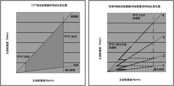
1.1Comparison
of traditional automatic transmission and CVT transmission
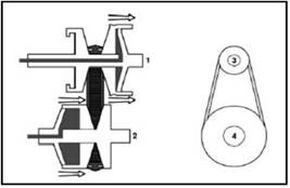
The following figure
shows the comparison of transmission ratio between CVT and manual or
conventional automatic transmission. The transmission ratio of a conventional
automatic transmission is a series of fixed values.
When the transmission
is in high gear, the transmission ratio shown on the right figure will vary
along the thick solid or dashed line according to the opening degree of the
throttle valve. However, with CVT transmission, the transmission ratio
variation diagram is shown on the left. The shift points of both transmissions
are related to the opening degree of the throttle valve operated by the driver.
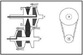
When
the opening degree of the throttle valve becomes larger, the engine speed
increases and the transmission changes into high gear.If use the traditional transmission,
the engine speed will be significantly reduced, but use the CVT transmission,
the engine speed will not reduce. In the condition of constant engine speed,
CVT transmission can be rotated into high gear by moving cone (see below). In
addition, there are other gear shift strategies available, which will help the
new user of CVT transmission accept it more quickly.
Drive
wheel speed (Nprim)
|
|
Throttle
valve partly open acceleration
|
|


Drive
wheel speed (Nprim)
|
|
Throttle
valve fully open acceleration
|
|
Throttle
valve fully open
|
|
Transmission
ratio change figure of conventional automatic transmission
|
|
Transmission
ratio change figure of CVT automatic transmission
|
|
Speed ratio change diagram of CVT transmission (left)
and 4-gear automatic transmission (right)
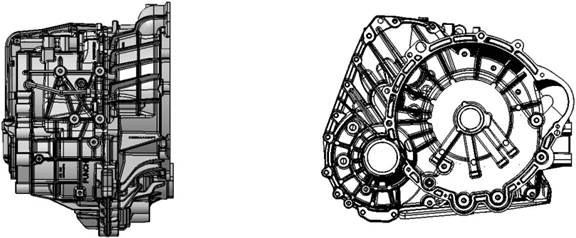
1.2
Transmission Schematic Diagram
1.2.1 Transmission
Three View Drawing

1.2.2 Transmission
Cutaway View
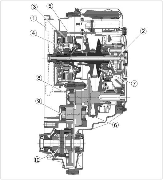
1.
Torsional shock absorber/Flywheel
2. Oil Pump
3.
Backward clutch
4.
Planet mechanism
5.
Forward clutch
6.
Steel belt
7.
Drive bevel gear
8.
Driven bevel wheel
9.
Countershaft
10.
Differential
1.2.3 Transmission
Exploded View
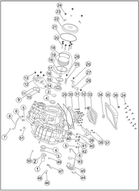
1.
Input shaft rubber guard sleeve 482235 26. Differential speed
sensor bracket fixing screw 481289
2.
Input shaft oil seal 481274 27. Differential speed sensor
bracket 482468
3.
Differential oil seal cover 481296 28. Revolution speed
sensor fixing bolt 481283
4.
Differential oil seal 483329 29. Oil pan washer 482504
5. Oil
filling screw plug washer 481247 30. Valve body assembly
482589
6. Oil
filling screw plug 481248 31. Valve body bolt 481311
7.
Breather pipe cap 483420 32. Plastic buckle 482253
8.
Breather pipe assembly 483114 33. Oil filter assembly
483165
9.
Driven bevel wheel shaft end cover O-type ring (small) 481254 34. Oil pan
magnet 481870
10.
Driven bevel wheel shaft end cover sealing ring 481877 35. Oil pan assembly
11.
Driven bevel wheel shaft end cover O-type ring (big) 481255 36. Oil drain
screw plug 482442
12.
Driven bevel wheel shaft end cover 482982 37. Driving mode
sensor fixing screw 481090
13.
Driven bevel wheel shaft end cover countersunk screw 482208 38.
Driving mode sensor 482493
14.
Drive bevel wheel shaft ball bearing 482294 39. Oil cooler screw
plug O-type ring 481258
15.
Drive bevel wheel shaft nut 481293 40. Oil cooler screw plug
482121
16.
Conical spring washer 481856 41. Oil level screw plug washer
481249
17. Oil
pump sealing ring 481826 42. Oil level screw plug 481250
18. Oil
pump O-type ring 481259 43.Main connector cover 482104
19. Oil
pump (with O-type ring) 483323 44.Main connector buckle 482105
20. Oil
pump bolt 481284 45.Main connector and inner wire
harness 482475
21.
Drive bevel wheel shaft end cover O-type ring 481253 46. Gear select
pull rod nut 481329
22.
Drive bevel wheel shaft end cover 481173 47. Gear select pull
rod 483185
23.
Drive bevel wheel shaft end cover buckle 481189 48. Gear select
pull rod nut washer 482584
24.
Drive bevel wheel shaft end cover bolt 481283 49. Oil seal (gear
select shaft) 482099
24. Oil
pan bolt 481283 50. Locating pin 483138
25.
Revolution speed sensor 482410 51. Metal buckle 481456
2. System Working Principle
These
components can be divided into three groups according to the corresponding
functions of the VT3 transmission:
·
Group 1 - mechanical transmission device. This part is designed to provide
mechanical transmission and torque transfer.
· Group 2 - control system and control system related
components. According to the load condition and driving requirement, the
control system ensures that the transmission transfers power and changes the
transmission ratio at the appropriate time.
· Group 3 - external
connecting device and some components that are connected to the external of
transmission. Some of these components are located in or connected to the
transmission, while others are part of the overall system but are distributed
elsewhere in the vehicle.
2.1
Mechanical Torque Transmit
2.1.1 Planet Mechanism
The
planetary mechanism enables the transmission to provide forward and backward driving
torque. The torque provided by the engine is usually transmitted to the
transmission through the input shaft on the planetary carrier. The multi-plate
clutch engaged in the forward direction can directly connect the planetary
carrier to the solar gear. At this point, the planetary carrier and the solar
gear become a rotating whole through engagement, and the engine torque is
directly transferred to the drive gear. The planetary gear does not transmit
any torque, so there is no mechanical loss to the planetary mechanism, and the
drive gear will rotate in the same direction as the engine. This is the forward
mode.
In
the reversing mode, engaging the reversing multi-plate clutch can keep the gear
ring in the planetary mechanism still, and the planetary carrier drives the
three pairs of planetary gear sets to make the solar gear rotate in the
opposite direction. At this time, the gear set's transmission ratio is 1:1.1,
and slight deceleration and torque increasing will occur to compensate for the
friction loss of the planetary mechanism.

Planet
mechanism
1. Planet gear
2. Input shaft
3.
Solar gear
4. Gear ring
2.1.2 Multi-disk
Clutch
There
are two sets of multi-disc wet clutches: one for forward and one for backward.
Each group of clutches has three friction plates with a total of six friction
surfaces. The hydraulic system controls the clutch to enable the vehicle to
move forward smoothly when the throttle valve is in any open degree. When drive
gear is engaged, controls the clutch engagement quantity to enable the vehicle
to stop. Cooling oil directly cools the clutch plate to prevent the friction
surface from overheating.

Clutch
in planet mechanism
1.
Forward clutch group 2. Backward clutch group
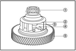
2.1.3 Bevel Gear and
Steel Belt
The main design feature
of the CVT transmission is a pair of V-shaped bevel gear connected by a steel
belt. The center distance between the drive gear and the driven gear is 155mm.
Each bevel gear is divided into two half: one half is fixed, the other half
slides along the axial direction, the inclination angle of both are 11°. The
24mm wide "Van Doorne" push-drive belt is used to transfer torque
between wheels (a 30mm belt is available for larger torque values). Lubricate
and cool the belt with a nozzle by means of an oil jet. To reduce the angle
error of the transmission belt when shifting gears, two moving half-wheels are
placed on the diagonal of the two, and each moving half-wheel is connected to
the hydraulic cylinder/piston. Hydraulic pressure is controlled by control
system, see "control system". Spherical splines prevent moving the
half wheel relative to their fixed half wheel rotation.
Since the sun wheel is
splined to the active cone wheel, the torque transmitted by the planetary gear
set can be directly applied to the active cone wheel. The steel belt transfers
power from the driving cone to the driven cone, and then from the driven cone
to the intermediate gear shaft.
The torque and speed of
the driven wheel are determined by the position of the belt. The size of the
two wheels is designed to provide a transmission ratio of 2.416:1 ~ 0.443:1,
with the maximum transmission ratio 5.45 times of the minimum one. The fuel
consumption is lowest when overspeed transmission ratio.
The
transmission steel belt consists of 450 steel plates and 24 steel belts fixed
together with 12 steel belts on each side.
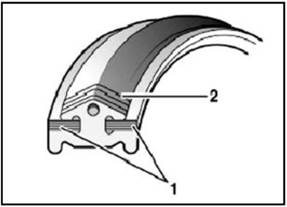
The
drive belt
2.1.4 Countershaft
1. Steel
belt 2. Steel plate
The
countershaft (pinion shaft) decelerates the two meshed helical gears between
the driven cone and the differential, thus ensuring that the drive shaft
rotates in the correct direction. The deceleration between driven cone wheel
and driving shaft greatly improves vehicle performance. The countershaft is
fixed by two conical bearings located in the clutch housing and the independent
bearing housing.
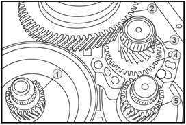
Gear
ring and intermediate gear
2.1.5 Differential
1.
Driving bevel shaft transmission gear
2.
Differential crow gear
3.
Transmission pinion
4.
Transmission intermediate gear
5.
Driven cone shaft gear
Like the manual transmission, the
torque on the crown wheel is transmitted to the wheels through the
differential, the crown wheel is bolted to the differential housing by eight
bolts, and the drive shaft is bolted to the differential by the traditional
ball-cage universal joint and gasket. Taper bearing is used to fix the
differential.
Differential assembly
1.
Differential bearing
2.
Differential shell
3.
Differential spider
4.
Differential planet gear
5. Differential
crow gear
2.1.6 Machinery
Operation
·
The transmission ratio number of traditional planetary automatic transmission
is limited, usually four, five or six; but the CVT is
different,
as the name suggests, CVT transmission ratio is continuous change. Low speed
gear (low transmission ratio) makes it easier for a stationary vehicle to
start. The diameter of the drive bevel gear is relatively small, but that of
the driven bevel gear is relatively large. The belt is used to transmit power
and torque. If the high-speed ratio is selected by increasing the diameter of
the drive bevel gear and reducing the diameter of the driven bevel gear, the
acceleration can be generated. Ensures optimum transmission ratio by controlling
the degree of variation.
CVT
transmission has two rotating gears of drive bevel gear and driven bevel gear,
each bevel gear is composed of two halves, one half is fixed, the other half
can be moved by hydraulic control. The position of the belt on the runner
determines the transmission ratio. If the moving half wheel is close to the
corresponding fixed half wheel, then the belt will move towards its periphery.
When the two cone wheels are separated, the circumference of the wheel will
become smaller, and the moving half wheel of the active cone wheel and the
driven cone wheel are in their respective diagonal positions. At this time, the
radius of the driving belt on the active cone wheel reduces, while the radius
of the driving belt on the driven cone wheel increases.
A
low transmission ratio is required for a vehicle to start. For this reason, the
driving cone wheels are separated so that the belt is attached to it and the
belt moves around the closed driven cone wheel. When the vehicle speed
increases, a high transmission ratio is required. For this reason, the moving
half wheel of the active cone wheel gradually approaches the corresponding
fixed half wheel, and the wheel circumference of the cone wheel increases. At
the same time, the driven cone wheel is forced to separate, and the radius
decreases, resulting in a higher transmission ratio. When the driving cone
wheel is completely closed and the driven cone wheel is completely separated,
the transmission ratio of overdrive gear is produced. The drive and driven
bevel gear rotate at a transmission ratio of about 1:2.5.
Belt
pulley position when in low gear
Belt
pulley position when in high gear
1.
Engine input
2.
Output to the wheels
3. Min diameter
driving wheel (low speed)
4.
Max diameter driven wheel (low speed)
1. Engine
input
2.
Output to the wheels
3.
Min diameter driving wheel Max diameter driven wheel
·
Gear selecting handle is in neutral or parking position
·
In this state, reversing clutch (2) and forward clutch (4) separates, can’t
make the wheel move.
 - Transmission input shaft (1) and
engine speed are the same.
- Transmission input shaft (1) and
engine speed are the same.
-
Backward clutch (2) separates.
-
Forward clutch (4) separates.
-
Planet gear (3) idle running around sun gear
- Sun gear not move,
drive gear (5), driven gear (7) and the vehicle
also keep still.
For
all automatic transmissions, the engine can only be started in neutral or in
park gear. In parking gear, the mechanical lock prevents the vehicle from
moving back and forth. In order to avoid damage to the transmission, the
parking gear can only be used when the vehicle is not moving.
1. Input
shaft 5. Drive gear
2.
Backward clutch 6. Driven steel belt
3.
Planet gear 7. Driven bevel gear
4.
Forward clutch
 · Gear selecting lever is in
forward gear, in this state, the forward clutch (4) engages to make the wheels
move.
· Gear selecting lever is in
forward gear, in this state, the forward clutch (4) engages to make the wheels
move.
-
Transmission input shaft (1) is the same with the engine speed.
-
Reversing clutch (2) separates.
-
Forward clutch (4) engages
-
Planet gear (3) of planet mechanism, sun gear and gear ring rotate together.
-
Drive gear (5) is the same with the engine speed, the direction is forward gear
direction.
- Driven gear (7) is the forward
gear direction, its speed depends on the transmission ratio in this running
state.
1.
Input shaft 6. Drive steel belt
2.
Reversing clutch 7. Driven cone shaft
3.
Planet gear 8. Driven bevel gear
4.
Forward clutch 9. Input shaft
5.
Drive bevel gear
· Gear
selecting lever is in reversing gear, in this state, backward clutch (2)
engages, gear ring (9) is locked in transmission housing. Planet gear (3) makes
the
rotating direction of sun gear
(10), drive gear (5) and driven gear (7) be opposite to the transmission input
shaft (1). Now reversing gear is selected.
-
Transmission input shaft (1) is the same with the engine speed.
 - Reversing gear (2) separates.
-
Forward clutch (4) separates.
- Gear ring (9) connects to transmission
case through backward clutch (2).
- Direct transmitting planet gear
(3) of transmission input shaft (1) make it rotate around the gear ring, thus
drive the sun gear (10), belt gear
(5) and driven cone gear (7) rotate
backward.
1. Input
shaft 6. Drive steel belt
2.
Backward clutch 7. Driven cone shaft
3.
Planet gear 8. Driven bevel gear
4.
Forward clutch 9. Gear ring
5.
Drive cone gear 10. Sun gear
2.2 Control System
The
functions of control system are as follows:
1.
Make the clamping force of the steel transmission belt tension adapt to the
engine torque to prevent the belt from slipping.
2.
Control the forward clutch and the backward clutch while driving.
3.
Provide the best transmission ratio for driving.
4.
Provide the necessary lubricating oil and cooling oil for the transmission.
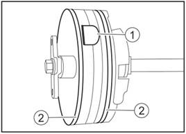
2.2.1
Oil Pump
The
oil pump in the transmission is the external engaging gear pump. The engine
drives the oil pump shaft, which reaches the inside of the oil pump through the
hollow drive bevel gear shaft. The pump shaft is splined to the planetary gear
rack. The pump shaft has been running at the engine speed. The pump oil is
about 10cm³. System pressure up to 40~50bar
depending on input torque.
Oil
pressure is not only used for hydraulic control of the transmission, but also
for lubrication.
Oil
pump full figure
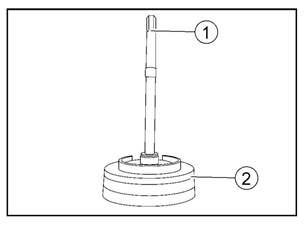
1. Oil
pump drive shaft 2. Oil pump assembly
Oil
pump inlet
1. Oil
pump inlet 2. Oil pump seal
2.2.2 Transmission
Control Device
The
transmission control device minimizes the tension between the belt and the
runner without slipping, and also provides the transmission ratio based on the
target values given by the driving strategy (calculated based on the input
(drive) and output (driven) speeds of the transmission). During the service
life, the performance degradation of the control device will be kept within a
certain range without obvious impact on vehicle comfort and belt tension.
2.2.3 Tension Control
Device
The tension control
device can obtain the required minimum tension force when the belt is not
slipping, which has the least impact on the transmission transmission
efficiency and the lowest fuel consumption.
In addition to normal
driving, the tension control device also takes into account the special
circumstances of transmission torque maximum input and output, so as to
maximize the protection of the transmission. The control device takes into account
anti-lock braking system (ABS), tire lock (no ABS) and other driving force
control system (such as ESP, anti-slipping control device, etc.). In addition,
the device also takes into account special roads and
conditions, such as passing through pot-holed road, road shoulder,
high and low adhesion coefficient transition, and tire slip (such as on low
adhesion coefficient road). The software can compare the transmission
performance of the transmission torque with the expected input torque of the
transmission. When the tension control device finds that the tension force is
insufficient, the ECU receives the instruction to reduce the torque, so as to
adjust the engine torque within the appropriate range. This function also
protects
the
transmission.
If there is no electronic drive circuit system in the
vehicle, the ECU transmits the torque signal through the CAN bus. If there is
no CAN bus, the transmission control system (TCU) software itself generates the
default torque signal.
2.2.4 Speed Ratio
Control Device
The transmission
controls the transmission ratio by controlling the input and output pressure to
balance the pressure on the drive and driven bevel gear. The transmission ratio
can be calculated according to the speed sensor signals of the drive bevel gear
and the driven bevel gear, and the required transmission ratio can be obtained
by changing the output pressure. The minimum pressure can be determined by the
tensioning method. The physical model of the transmission helps to quickly
adjust the pressure level to the variable operating point. The control software
also considers the interference from other components of the transmission, so
it was developed to minimize delay errors and target speed ratio errors as
possible(to improve fuel economy).
In
order to meet the requirements of transmission machinery and durability limit
state, we developed some driving strategies in limit state. In addition to the
speed limit, the rate of change of the transmission ratio (the set point) is within
the allowable range through the software. In addition, the software also
prevents the engine speed from exceeding a certain limit due to the vehicle
speed and the condition of the gear lever (POS). To achieve this limitation,
the software will require a reduction in engine torque or a shift of the
vehicle into higher gear.
2.2.5 Transmission
Control Unit
The
software controls transmission is integrated in TCU (Transmission Control
Unit). TCU is installed inside the cab.
2.3
External Device
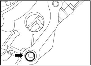
2.3.1 Oil Cooler
Connector
There
are two oil cooler pipes in front of the transmission housing. The inlet of one
oil cooler is installed next to the engine radiator, to keep the temperature of
the lubricating oil below 120 °C. The oil in the transmission flows out from
the right port, which should be connected to the lower port of the oil cooler.
The
oil of the oil cooler enters into the transmission from the port on the left
side of the transmission, so the port on the left side of the transmission
should be connected to the upper port of the oil cooler.
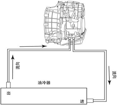
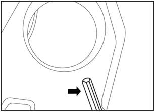
2.3.2 Shift lever
Oil
cooler pipe connector
The gear position of
VT3 transmission may include stop gear (P), reverse gear (R), neutral gear (N),
forward gear (D), and sport mode (S).
Customer can customize
the configuration of the shift lever. For the sake of safety, it is recommended
to apply gear shift locking device as starting protection.
CVT transmission can
also achieve manual mode, which requires the addition of new pins on the TCU to
receive signals, and the calibration of the maximum speed of the engine within
a certain range. All JAC CVT transmissions have manual mode.
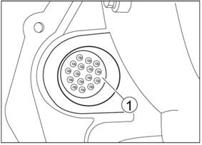
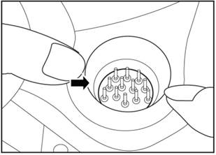
2.3.3
Main Connector
Main connector is on
transmission housing, includes 16 pins. The wiring harness connects through
circular connector.
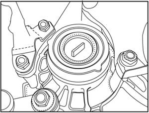
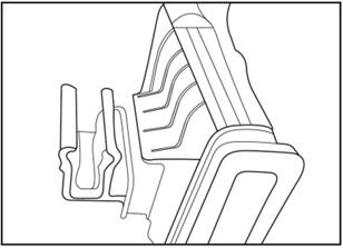
2.3.4 Torsional shock
absorber
Most conventional
automatic transmissions use a torque converter to connect the engine to the
input shaft, but this one uses a torsional shock absorber.
3.General Information
3.1
Towing Vehicle
Vehicle equipped with
VT2 or VT3 transmission cannot be directly towed, because only when the engine
is running, oil pressure can be generated in the cone wheels and the
transmission belt can run. Therefore, the front wheel must be lifted from the
ground when towing.
3.2
Maintenance Period
Every 60,000km or two
years (whichever is the first), the transmission oil and oil filter must be
replaced. Therefore, the transmission is equipped with oil drain plug and
refueling screw plug. Vehicle manufacturer can reduce the transmission
maintenance period, so that it can match the vehicle’s standard maintenance
period.
3.3
Lubricant Oil Specification
Please use MOBIL(ESSO)
EZL799(A) or IDEMITSU CVTF-EX1, the two types oil can be mixed, but it’s not
advised.
The use of other oil
may result in damage to the interior of the gearbox. Once other oil is used,
this gearbox cannot be claimed.
3.4
CNG (Compressed Natural Gas), LPG (Liquefied Petroleum Gas) etc
Risks
of switching to CNG:
--
the vehicle will have a different or unstable torque diagram, which will result
in:
•
different performance
•
very poor driving response
•
generate fault codes
•
clutch movement problem
•
self-learning problems
•
steel belt slips
PUNCH does not allow vehicles to be
changed to other fuel systems: CNG, LPG,...PUNCH immediately discontinued this
gearbox warranty as soon as the vehicle was fitted with another fuel system.
4.
Technical Parameter/Maintenance Parameter
|
No.
|
Project
|
Parameter
|
|
1
|
Transmission
|
VT3
|
|
2
|
Type
of lubricant oil
|
MOBIL(ESSO) EZL799(A)/DEMISTU
CVTF-EX1
|
5. Torque parameters
|
No.
|
Project
|
Tightening Torque (N · m)
|
|
1
|
Oil
filler plug
|
21±3
|
|
2
|
Driven bevel wheel shaft end cover
countersunk screw
|
9.5±0.95
|
|
3
|
Drive cone gear shaft nut
|
197.5±17.5
|
|
4
|
Oil
pump bolt
|
10±1
|
|
5
|
Driven bevel gear shaft end cover bolt
|
9.5±2.5
|
|
6
|
Oil
pan bolt
|
9±1
|
|
7
|
Speed sensor fixing bolt
|
8.5±2
|
|
8
|
Speed sensor bracket fixing screw in
differential
|
9.5±0.95
|
|
9
|
Valve
bolt
|
11±1
|
|
10
|
Oil
drain screw plug
|
11±1
|
|
11
|
Driving mode sensor fixing screw
|
9.5±0.95
|
|
12
|
Oil
level screw plug
|
15±2.25
|
|
13
|
Gear shifting handle nut
|
14.5±1.5
|
6.
Special Tool
|
No.
|
Tool No.
|
Tool name
|
Tool
illustration
|
Usage
|
|
1
|
16G0049
|
Drive
bevel gear shaft bearing plug
|

|
Remove the drive bevel gear bearing
|
|
2
|
16G0043
|
Assembly
tool of gear shift shaft oil seal
|

|
Install gear select
shaft oil sealing
|
|
3
|
16G0050
|
Drive
bevel gear shaft bearing punch
|

|
Install
the drive bevel gear shaft ball bearing
|
|
4
|
16G0048
|
Drive bevel gear
shaft bearing removal tool
|

|
Remove the drive
bevel gear shaft ball bearing
|
|
5
|
16G0041
|
Assembly tool of
input shaft oil seal
|

|
Install the input shaft oil seal
|
|
6
|
16G0040
|
Input shaft oil
seal locating bushing
|

|
Install the input shaft oil seal
|
|
No.
|
Tool No.
|
Tool name
|
Tool
illustration
|
Usage
|
|
7
|
16G0042
|
Disassembly tool
of gear shift shaft oil seal
|

|
Remove the gear select shaft oil sealing
|
|
8
|
16G0046
|
Locating pin of
hydraulic control module
|

|
Install the
hydraulic control block
|
|
9
|
16G0038
|
Differential oil
seal installation tool
|

|
Install the
differential oil seal
|
|
10
|
16G0045
|
Oil pump removal tool
|

|
Remove the oil pump
|
|
11
|
16G0044
|
Air pipe assembly tool
|

|
Install the respirator hose
|
|
12
|
CVT-HDFJ-1
|
N gear
installation auxiliary tool
|

|
Limit the
transmission gear shift rocker arm position
|
Chapter II Driving
strategy
1. Function Characteristic
of Parking and Neutral Gear
No matter what kind of
transmission, the engine can only be started in the parking and neutral state.
The mechanical lock in the parking gear prevents the vehicle from moving back
and forth. Had better be in vehicle static condition uses parking gear, in case
injury transmission.
If
you accidentally use the parking gear when the speed is high, the parking
device can only work if the speed is reduced to about 5km/h.
1.1
Parking Locking Mechanism
When the vehicle starts
up, TCU will control the starting relay, and the starting relay can control to
start the engine. The vehicle's gear is controlled by an internal driving mode
sensor, which is connected directly to the gearshift lever. To shift parking
(P) or neutral (N) to drive (D) or reverse (R), the brake pedal is pressed. If
the brake pedal is not pressed, the gear lever remains locked in either P or N.

Parking lock mechanism
1.2
Function of D/R Gear
1.2.1 General
operation
1.
Parking stop pawl 2. Driven cone wheel
When
driving, the operation of this transmission is completely different from that
of traditional automatic transmission, so you should pay attention to adapt.
Example: If you press the accelerator pedal too hard, the engine speed will
increase obviously, but the speed will not change much. This feature is normal
for CVT transmission, but if the driver does not know about the transmission,
it may be mistaken for a faulty gearbox.
Other
analogies to traditional automatic transmissions may also exist.
1.2.2
Self-adaption updating
Whether
forward or reverse, the corresponding clutch should be calibrated again to
achieve the best effect in its service life.
1.2.3 Creep
According
to the performance of automatic transmission, when the shift lever is in
forward gear (D) or reverse gear (R), if the driver releases the brake pedal,
the vehicle will start crawling (flat road). If the road slope is less than 8
°, the vehicle also can crawl; If the road slope is greater than 8 °, the
vehicle will be slightly backward, which is the same with the vehicle equipped
with hydraulic torque transmission, it will not backward if the slope degree is
not large. Regardless of the slope of the road, the maximum speed at which the
vehicle climb will be less than a limit (8kph). Especially downhill, the
control system will allow the clutch to switch from separation to
"engage" mode, allowing the engine to brake during the glide.
1.2.4 Idling parking
(only for D gear state)
The
VT3 transmission can idle stop. The vehicle (battery status, A/C ON/OFF) and
the transmission (without affecting the transmission durability) can idle stop
under certain conditions. If all conditions are met, the internal combustion
engine can stop at rest. Only when the brake pedal is released and the engine
starts up again and the transmission works quickly can the vehicle move forward
and backward.
The
idle stop feature is particularly useful for hybrid drives, but is useless for
standard drives without a special starter or starter motor.
1.2.5 Acceleration and
deceleration
The
acceleration process mainly provides acceleration according to the driver's
requirements and driving conditions. At this time, the change trend of engine
speed corresponds to the initial speed, so as to achieve the best driving
comfort.
The
clutch controller also provides some means of compensating for the difference
in clutch wear (it differs between different vehicles) to ensure driving comfort.
1.2.6 Acceleration
support
In
order to achieve optimal driving comfort, it is necessary to determine the most
appropriate engine speed, which is between the minimum traction engine speed
and the engine speed when the vehicle maintains a constant speed (economic
speed) cruise state.
The
transmission control system provides functionality to meet these requirements
by using a combined control mode between the transmission (ratio control) and
the starting clutch. Therefore, when the vehicle starts, the control target is
always focused on the driving performance of the higher engine speed related to
the acceleration of the vehicle, while when the vehicle cruises or glides, the
control target is transferred to the fuel economy of the transmission system.
1.2.7 Deceleration
If
the driver presses the brake pedal at the same time as the accelerator pedal,
the engine speed will be limited to a certain range (similar to the torque
converter). Therefore, the gearbox needs to be combined with the engine control
system to block torque so that the gearbox can react quickly to the driver's sudden release of the
brake pedal and start to control the clutch. Long-term use will cause high
temperature loss of the clutch, the transmission also has the risk of damage,
so we use the monitoring function to
detect
these dangerous conditions. Activate the transmission's internal diagnostic
system to open the clutch. If the driver keeps his foot on the gas pedal, the
engine will rise up to its maximum speed. In addition, the clutch controller
can also follow the highest control goal in other cases, to ensure the original
safety and improve the driving comfort.
1.2.8 Driving and brake
When the vehicle
decerates to stop, the clutch is separated again to prevent the engine from
stopping. The clutch pressure is controlled to drop steadily to gradually
separate the clutch, so as not to cause torque fluctuations. Therefore, the
controller provides different modes according to the change of speed to
separate the clutch. The clutch pressure control also controls the power of the
hydraulic control system according to the oil temperature of the transmission.
The clutch can be quickly ready to start after separation.
In
order to make the driving comfort optimal during the vehicle braking and
starting process, the transmission software and other transmission control
device work together, this role makes the torque transmission temporarily
interrupted, idle speed increase.
1.2.9 Clutch combines/separates when driving
If
the clutch is not used while driving, the transmission controller has little
effect on the comfort of driving, as the absence of the clutch has nothing to
do with the characteristics of the hydraulic system. In such case (low load,
stopping, low engine speed), the driving comfort may be reduced when the clutch
is applied again compared with when the clutch is applied in the stationary
state.
1.3 Failure Default Mode
When
the software detects a system error, the default rule is applied.This is
transmitted to the drive through the instrument group's fault display. The
driver will take a different default driver state depending on the severity of
the error. In some cases, the main relay will be turned on. All fault codes
will appear on the OBD.
1. Transmission Oil
1.1
Special Tool (No)
1.1.1 Oil level check
instruction
Chapter
III Usage Instruction
The
following oil level check should be carried out whenever draining the
transmission oil or replacing new transmission. There is no oil in the
transmission as service part, and after being installed on the vehicle, it need
to add 4.5±0.05L ESSO EZL799(A) or
Idemistu CVTF-EX1 oil, please add
oil and check the oil level according to the following methods. 1. Shift the
operation lever to P gear position.
2.
Remove the oil filling plug (3) on the top.
3.
Ensure that the oil drain plug (1) is assembled.
4.
Fill 4.5±0.05 L transmission oil Esso EZL 799A to the transmission oil from the
oil filling plug (3) on the top.
5.
Reinstall the oil filling plug (3). Tightening torque (M14) : 21N·m.
6.
Step the brake pedal.
7.
Start the engine.
8.
Run the engine for 10 seconds.
9.
Shift the shift lever away from P gear position.
10.
Note: the sound of air circulating through the system may be heard at the
initial start-up. This is normal operation.
11.
Switch the operation lever to each gear (P-R-N-D) and remain in each gear for 5
seconds before switching to the next gear.
12.
Shift the operation lever to D gear position.
13.
Release the brake pedal.
14.
Step lightly on the accelerator pedal to 60km/h (engine speed must not be
higher than 2500rpm).
15.
Release the accelerator pedal and tap the brake brake until the vehicle stops.
16.
The above two steps should be performed at least twice.
17.
Driving around at least 5 minutes (hope temperature rises from 30 ℃ to 50 ℃).
18.
Step the brake pedal.
19.
Wait for 2 seconds.
20.
Shift the operation lever to R gear position.
21.
Release the brake pedal.
22.
Wait for 10 seconds.
23. Step the brake pedal.
24.
Wait for 2 seconds.
25.
Shift the operation lever to N gear position.
26.
Keep the engine idling.
27.
The engine must be running and the lever must be in N gear.
28.
Check the oil temperature: must be between 30 ℃ to 50 ℃.
29.
Wait 2 minutes until oil level stabilizes.
30.
Remove the oil level plug (2) (the engine is still running).
31.
Wait a few minutes until the oil drips off from the oil level plug.
32.
Reinstall the oil level plug.
33.
Tighten oil level plug (tightening torque (M14) : 21N·m).
34.
Stop the engine and shift the lever to P gear position.
1.2
Oil Level Inspection
If the initial oil
filling is correct, the oil level should be in the correct position (oil level
bolt position). Normal allowrance (such as new transmission residual oil and
production line fueling allowrance) should be oil level bolt position, oil
level can be ±0.165L.
1.
Check the oil level of the transmission
1)
Remove the oil filling bolt on the upper end of the transmission.
2)
Add accurate 0.5L±0.05L oil to the transmission.
3)
Install the oil filling screw plug. Tightening torque 18~4N·m.
4)
Starting the engine to make transmission temperature rising to about 60 ℃.
5)
Place the vehicle on the flat ground.
6)
Press the brake pedal, and wait 2 seconds, and then shift to P gear position.
7)
Keep the engine idling running.
8)
Remove the oil level inspection bolt when the engine is idling.
9)
Release the oil accurately (0.335L at least, 0.665L at most)
Min of 0.235L (0.5
ADDED oil-0.165 tolerances - 0.1L = 0.235L) oil will flow from the gearbox, and
if less than that, the original oil level is too low.
Max of 0.565L (0.5 ADDED
oil+ 0.165 tolerances - 0.1L = 0.565L) oil will flow from the transmission, and
if less than that, the original oil level is too high.
▲Note:
All data comes from when the transmission oil temperature is 60 ℃.
10)
Install new gaskets and tighten oil level bolts. Tightening torque 18~24N·m
11)
Stop the engine.

Oil
draining bolt (1) Oil level bolt (2)

Oil filling screw plug (3)
2.
Disassembly and Assembly of Shift Control Mechanism System Component and Pull
Cable Adjusting Method
2.1.
Special tool
|
1
|
CVT-HDFJ-1
|
N gear installation auxiliary tool
|

|
2.2 Gear Shift Pull Rode Assembly
This procedure
describes how to correctly connect the gearshift lever. Failure to follow this
instruction may result in transmission gear disorder. The dashboard will always
show the transmission gear status regardless of the gear lever position. A
precise
shift wire drawing installation
allows the instrument panel and shift lever to indicate the same shift status
(PRND). If replacing the gear shift control mechanism, select &shift gear
pull cable, pull cable bracket, shift rocker arm and sleeve, pull rod assembly,
transmission
or other
components that affect the transmission gear shifting operation control, they
must be re-adjusted, otherwise there will be a shift disorder or even cause the
vehicle can not run and other faults. The removal and adjusting method are as
shown below:
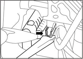
2.2.1 Disassembly and Assembly of
Shift Control Mechanism System Component
 1) Replace pull cable bracket,
first loosen the gear shift&select pull cable and shift rocker arm, make the
pull cable
1) Replace pull cable bracket,
first loosen the gear shift&select pull cable and shift rocker arm, make the
pull cable
Separate from
the rocker arm, and separate the pull cable from pull cable bracket, and then
replace the pull cable bracket. Assembly of pull cable:
2)
Replace gear shift rocker arm and shift rod
▲Note: ① Consider the
operating space, before replacing the "gear select&shift pull cable
assembly", put the shift lever to the P gear position, and then take down
the pull cable and
transmission
control mechanism connection end, but put the shift lever to the P gear
position again before installing the pull cable. ② Before replacing the other
parts, must ensure that the gear shift control mechanism gear lever in the P
gear position; ③ Connect the gear select&shift pull cable to the
transmission gear select rocker arm by bolts and nuts (when tightening the
nuts, must not bend the transmission gear shift rocker arm or pull cable).
 A. Disconnect the gear
select&shift pull cable and the gear shift rocker arm.
A. Disconnect the gear
select&shift pull cable and the gear shift rocker arm.
B. Loosen the rocker arm fixing
bolt Q1840830F61 (pay attention to the rocker arm sleeve)
C.
Loosen the transmission end pull rod fixing nut Q32008F61L D.Disconnect the
gear select rocker arm and gear select pull rod
E.
Connect the gear shift rocker arm and gear shift pull cable ball
F.
Tighten the gear shift rocker arm and transmission
(Q1840830F61),
tightening torque:20~28Nm
G.
Shift gear forward and backward, relieve stress, and shift to P gear position
at last
H.
When the gear shift pull rod is fixed connected to the transmission, the gear
shift pull rod lock is unlocked. Pay attention to the control mechanism and
transmission swing arm in P gear position, tighten the nut Q32008F61L in P gear
position, the tightening torque is 20~28Nm, and finally press the gear shift
pull rod lock to lock the pull rod.
Ball
joint decorative ring
|
|
 3) Replace the gear select &
shift pull cable assembly
3) Replace the gear select &
shift pull cable assembly
Auxiliary
dashboard assembly
|
|
a—Put the gear
shift lever to the N gear position, remove the protective guard (the protective
guard is connected to the auxiliary dashboard by buckles), and clockwisely
rotate the gear select&shift ball joint decorative ring. After the
decorative ring is shaken, pull out the gear select& shift ball joint with
force.
b—Remove
the auxiliary dashboard
c—Disconnect
the pull cable and operating mechanism
d—Loosen
the 2 M8 nuts on the vehicle body (Q32008F61)
 e—Disconnect the pull cable and the
gear shift rocker arm
e—Disconnect the pull cable and the
gear shift rocker arm
Ball
joint decorative ring
|
|
f—Disconnect
the pull cable and transmission with rear suspension
g—Pass
the new gear select&shift pull cable assembly into the cabin through the
engine compartment.
Auxiliary
dashboard assembly
|
|
h—Tighten the 2
M8 nuts (Q32008) on the front wall of the vehicle body Tightening torque is
20~28Nm
i—Connect the cable joint (at
transmission control mechanism end) to the pin shaft of the transmission
control mechanism.
 j—Install the pull cable damper in place
k—Install
the pull cable and suspension bracket in place.
1—Install
the pull cable and rocker arm in place.
1)
Replace the shift control mechanism assembly
—Put
the shift lever to P gear position, and operate according to the pull cable
maintenance steps a-b-c
—After finish step c, remove the 4
fixing bolts Q146B0830TF38, and take down the shift control mechanism
—Install the gear shift control
mechanism tightening torque is 20~28Nm
—Connect
the cable joint (at transmission control mechanism end) to the pin shaft of the
transmission control mechanism.
—Install
the pull cable damper in place
3.
Half shaft
3.1
installment
When
installing the half-shaft to the full transmission, we strongly recommend using
PUNCH 480145 tool to protect the differential oil seal. If the differential
shaft is damaged, the transmission will inevitably leak oil. Using special tool
will significantly reduce the chance of oil seal damage.
1)
Remove the oil seal protective cover.
2)
Install the tool on the half-shaft oil seal and install it well.
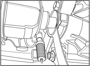
3)
Put the half-shaft into the transmission at a maximum depth of 4cm.
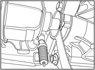
4)
Put the half-shaft into the transmission at a maximum depth of 4cm, with a
distance of 2cm between the half-transmission and the tool.
5) Take
down the tool
4)
Fully push the half shaft into the transmission, and the installation of half
shaft finished.
4. Differential oil seal
4.1
Fault code instruction
There
is oil seal damage or oil leakage, half shaft damage or oil leakage.
4.2 Special tool
|
1
|
480143
|
Differential oil
seal installation tool
|

|
4.3 disassemble
 1. Discharge the transmission oil.
2.
Remove the half shaft. Refer to the drive shaft.
3.
Remove the differential oil seal.
1)
Use large flat screwdriver to pry out the oil seal.
▲Note: Be careful not
to put the flat screwdriver too deep to protect the shell.
4.4
installment
1.
Install the differential oil seal
1)
Put the new oil seal to the shell.
 2) Put the special tool 16G0038 on
the oil seal and hammer it into the shell with rubber hammer to ensure the
installation in place.
2) Put the special tool 16G0038 on
the oil seal and hammer it into the shell with rubber hammer to ensure the
installation in place.
▲Note: The depth of the oil seal should
be 3mm±0.3mm from the shell edge.
2.
Install the half shaft.
3. Fill
the transmission oil.
5.Input shaft oil seal
5.1 Fault
code instruction
Input
shaft oil seal damage or oil leak.
5.2
Special tool
|
No.
|
Tool No.
|
Tool name
|
Tool
illustration
|
|
1
|
16G0041
|
Assembly tool of
input shaft oil seal
|

|
|
2
|
16G0040
|
Input shaft oil
seal locating bushing
|

|
5.3 disassemble
 1. Discharge the transmission oil.
2. Remove the transmission assembly. Refer to the
transmission assembly.
3. Remove the input shaft oil seal.
1)
Remove the oil seal from the shell with large flat screwdriver.
▲Note: Pry along the
middle of the oil seal to the outside, must be very careful, or it will damage
the transmission input shaft.
 5.4 installment
1.
Install the input shaft oil seal.
1) Place the oil seal
locating bushing 16G0040 on the input shaft.
2) Place the new oil seal on
the locating bushing.
 3) Put the special tool 16G0041 on
the input shaft, hit the special tool with a rubber hammer and install it in
place.
3) Put the special tool 16G0041 on
the input shaft, hit the special tool with a rubber hammer and install it in
place.
2.
Install the transmission.
3. Fill the transmission oil.
6.
Gear select shaft oil sealing
6.1 Fault
code instruction
Gear
select shaft oil sealing leaks oil.
6.2
Special tool
|
No.
|
Tool
No.
|
Tool name
|
Tool
illustration
|
|
1
|
16G0043
|
Assembly tool of
gear shift shaft oil seal
|

|
|
2
|
16G0042
|
Disassembly tool
of gear shift shaft oil seal
|

|
6.3disassemble
1.
Discharge the transmission oil.
2.
Remove the transmission.
 3. Remove the gear select shaft
lever.
3. Remove the gear select shaft
lever.
4.
Remove the gear select shaft oil seal.
1) Put the
special tool 16G0042 on the shift shaft, and screw the special tool into the
oil seal with wrench.
▲Note: Press the top of the wrench
so that special tool screw into the oil seal.
2)
Turn the bolt on the special tool with the tool to pull the gear select shaft
oil seal out of the shell.

3)
Rotate the small bolt to pull out the oil seal.

4) Take out the oil seal.
6.4
installment
1.
Install the gear select shaft oil seal.
1)
Apply vaseline or lubricating grease to the tip of the oil seal punch 16G0043.
2)
Install the new oil seal lightly on the punch 16G0043.
3) Put the special punch 16G0043
with oil seal on the gear shift shaft and tap with a hammer until it is
installed in place.
 4) Take out the punch 16G0043.
▲Note: Rotate and pull
the punch out, or else it may cause the oil seal and the punch be pulled out
together.
2.
Install the gear select lever, and tighten the nut with new washer and nut,
torque 14.5N·m±5N·m.
3.
Install the transmission.
4. Fill the transmission oil.
7. Drive Bevel Gear End Cover
7.1
Fault code instruction
Drive
bevel gear end cover leaks oil
7.2
disassemble
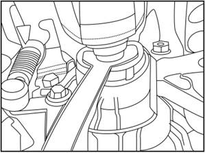
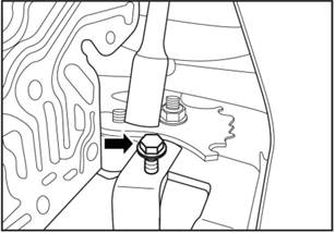
1.
Dischrage about 1L oil from the transmission (see replacing the oil filter).
2. The
transmission does not need to be removed from the vehicle. It is easier to
replace the engine and transmission if they are placed together.
3.
Remove the bolt and remove the clasp. Remove the cover with a larger flat
screwdriver, and place a cloth pad under it to prevent damage to the
transmission housing.
4.
Remove the end cover with a larger flat screwdriver and put a piece of cloth
under it to prevent damage to the ring transmission housing.
5.
Remove the larger type O-ring and throw it away with the end cover.
7.3
installment
1.
Install a new O-ring.
2. Replace a new end cover and
tighten the bolt and buckle. Torque: 9.5N·m±2.5N·m.
3.
Fill 1L oil into the transmission.
8.
Oil Pump
8.1
Fault code instruction
If
the transmission pressure is found to be too low or the driving process
vibration or abnormal phenomenon, there are two important components can cause
this problem: oil pump and hydraulic control block. Use the fault code to
determine which one needs to be replaced. In most cases it is not completely
clear which one is the problem, just replace one by one to see whether the
problem is solved.
8.2
Special tool
|
No.
|
Tool No.
|
Tool name
|
Tool
illustration
|
|
1
|
480141
|
Oil pump removal
tool
|

|
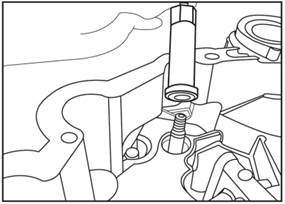
8.3 disassemble
1.
Remove the end cover according to the sequence of replacing the drive bevel
gear end cover.
2. Remove the 6 bolts from the oil
pump and put the special tool on the oil pump shaft.

3.
Pull out the oil pump with special T-tool (480141).
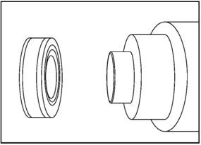
4. When replacing new oil pump, it
must be confirmed that two new 0-rings are put on the new oil pump. Be careful
not to pull out the conical return spring, and make sure the larger end is
facing to the oil pump.

-
42 -
8.4
installment
1.
Install oil pump
1)
When installing the new oil pump, make sure to put two new O-rings on the new
oil pump.
▲Note:
Do not take out the conical return spring, and make sure the larger end is
facing to the oil pump.
 2) Reinstall the 6 bolts, and tighten them with the
torque of I0N·m+/-IN·m.
2) Reinstall the 6 bolts, and tighten them with the
torque of I0N·m+/-IN·m.
3) Put the end cover back according
to the steps, do not replace the O-ring and end cover.
▲Note: Do not replace the O-ring
and end cover.
3.
Install the transmission
4.
Fill the transmission oil.
9. Drive Bevel Gear Shaft
Ball Bearing
9.1
Fault code instruction
Replace the drive bevel
gear shaft ball bearing if it wear out. A worn drive bevel gear shaft ball
bearing will have large noise, and the noise varies with engine speed. So if
you change from D gear to manual mode at constant speed and the noise suddenly
increases, it is very likely that the bearing is damaged. Because after
changing to manual gear, the speed remains the same but the engine speed
increases.
9.2
Special tool
|
No.
|
Tool No.
|
Tool name
|
Tool
illustration
|
|
1
|
16G0049
|
Drive bevel gear
shaft bearing plug
|

|
|
2
|
16G0050
|
Drive bevel gear
shaft bearing punch
|

|
|
3
|
16G0048
|
Drive
bevel gear shaft bearing removal tool
|

|
|
4
|
16G0047
|
Drive
bevel gear shaft big nut removal and installation sleeve
|
|
9.3 disassemble
1.
Discharge the transmission oil.
2.
Remove the transmission.
3.
Remove the drive bevel gear shaft end cover. Refer to the drive bevel gear
shaft end cover.
 4. Remove the oil pump. Refer to
the oil pump.
4. Remove the oil pump. Refer to
the oil pump.
5. Remove
the drive bevel gear shaft ball bearing.
1)
Take out the conical return spring.
2)
Mark the shaft and nut.
3)
Remove the nut with the special sleeve.
4)
Remove the dust cover from the bearing with flat screwdriver.
5)
Put the protection plug on the shaft.

6) Assemble bearing removal device
(16G0048), and hook the outer ring of the bearing with its foot.

7) Tighten the middle bolt to pull out the bearing.

9.4
installment
1.
Install the drive bevel gear shaft ball bearing
1) Clean
the sealant of the drive bevel gear shaft and oil pump drive shaft lock belt,
and oil pump chamber.
2) Put the new bearing in place and
install it with a special punch (16G0050).

3) Knock
the punch into place with a rubber hammer.
 4) Tighten the nut so that the mark
on the shaft coincides with the mark on the nut. Standard coincidence degree
±5°
4) Tighten the nut so that the mark
on the shaft coincides with the mark on the nut. Standard coincidence degree
±5°
5)
Install the conical return spring.
2.
Install the drive bevel gear shaft end cover.
▲Note: Do not replace
the O-ring and end cover.
3.
Install the transmission.
4.
Fill the transmission oil.
▲Note:
The larger end of the diameter is toward the oil pump.
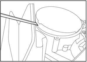
10.Driven Bevel Gear Shaft End Cover
10.1
Fault code instruction
Driven
bevel gear shaft end cover damaged or leaks oil
10.2
disassemble
1.
Remove the driven bevel gear shaft end cover.
1).
Remove the 4 countersunk screws.
2) Take down the two
O-rings and the one sealing ring on the end cover.

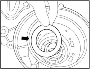
10.3
installment
1.
Install the driven bevel gear shaft end cover.
1)
Install the two O-rings and the one sealing ring on the end cover.
2)
Clear the thread glue in the 4 screw holes on the shell.
3).
Tighten the 4 screws. Tightening torque 9.5±0.95N·m.
11.Oil pan
11.1
Fault code instruction
Oil
pan damaged or leaks oil
11.2
disassemble
1.
Discharge the transmission oil.
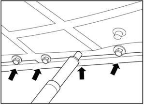
2)Remove the oil pan.
1)
Install the 13 bolts on the oil pan.
11.3
installment
1.
Install the oil pan.
1)
Install the new oil pan and gasket.
2)
Install the oil pan bolts according to the sequence as shown in the picture.
▲Note:
Use new bolt gasket. Tightening torque 9.5±1N·m.
2.
Fill the transmission oil.

12. Oil Filter
12.1
Fault code instruction
Oil
filters should be replaced at least every 60,000km or 2 years (whichever comes
first), and the period can be reduced according to the standard of each
manufacturer.
12.2
disassemble
1.
Discharge the transmission oil.
2.
Remove the oil pan. Refer to the oil pan.
3.
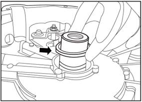
Remove the oil filter.
1)
Take out the oil filter slightly and abandon it.
12.3
installment
1.
Install the oil pan.
1)
Install oil filter with a new O-ring, and lubricate it with ESSO EZL799 (A).
2)
Gently press the oil filter in place.
 ▲Note: The hole in the middle of the oil filter is
matched with the middle bolt on the hydraulic control block.
▲Note: The hole in the middle of the oil filter is
matched with the middle bolt on the hydraulic control block.
3)
Clean the magnet and the oil pan.
2)Install oil pan.
3. Fill
the transmission oil.
13. Driving Mode Sensor
13.1
Fault code instruction
The
fault code should display the fault of the driving mode sensor, replace the
driving mode sensor.
13.2
disassemble
1.
Discharge the transmission oil.
2.
Remove the oil pan. Refer to the oil pan.
3.
Remove the oil filter. Refer to the oil filter.
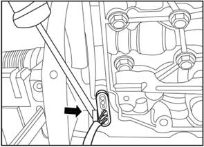
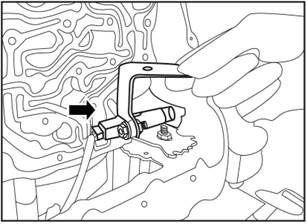
4.
Remove the driving mode sensor.
1)
Remove the 2 screws on the driving mode sensor.

2)
Carefully take down the driving mode sensor from the hydraulic control block.
▲Note: Behind the sensor is a small
pin with hydraulic pressure. The metal slider on the control block is fixed
together, pressing the sensor down to release the pin from the slider.

3) Use flat screwdriver to open the lock on the sensor
joint, and press the white lock to separate the joint.
13.3
installment
1.
Install the driving mode sensor.
1)
Take a new sensor, connect the connector, and press the white lock button
inside to lock it.
2)
Put the pin behind the sensor on the metal slider and install it in place.
3)
Move the sensor to expose the bolt hole.
4)
Tighten the 2 fixing screws. Tightening torque 9.5±0.95N·m.
2.
Install the oil filer.
3)
Install the oil pan.
4. Fill
the transmission oil.
14.
Hydraulic Control Module
14.1 Fault
code instruction
If
the transmission pressure is found to be too low or the driving process
vibration or abnormal phenomenon, there are two important components can cause
this problem: oil pump and hydraulic control block. Use the fault code to
determine which one needs to be replaced. In most cases it is not completely
clear which one is the problem, just replace one by one to see whether the
problem is solved.
|
No.
|
Tool No.
|
Tool name
|
Tool
illustration
|
|
1
|
16G0046
|
Locating pin of
hydraulic control module
|

|
14.2
disassemble
1.
Discharge the transmission oil.
2. Remove the oil pan. Refer to the oil pan.
3. Remove the oil filter. Refer to the oil filter.
4. Remove the driving mode sensor. Refer to the
driving mode sensor.
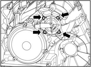
5. Remove the hydraulic control module
1) Remove the bolts according to
the sequence from 20 to 1 as shown in the picture.

2) Take out the hydraulic control module, and separate the
▲Note:
Use flat screwdriver can easily take down the connector.

14.3
installment
1.
Install the hydraulic control module
1) Install the hydraulic control
module in place and put a small pin behind the hydraulic control module in the
correct position.

2)
Ensure that the metal slide and the pin on the shift cam are installed rightly
3) Install the middle bolt and
tighten it by hand.
4) Install the special tool 16G0046
in the bolt hole in the upper left angle.
5) Press the wire of the drive
bevel gear speed sensor on the upper left corner of the hydraulic control
module.
 6) Install all the bolts of the
hydraulic control module and tighten them in the order from 1 to 20.
6) Install all the bolts of the
hydraulic control module and tighten them in the order from 1 to 20.
Tightening
torque 11N·m.
2. Install the driving mode sensor.
3. Install the oil filter.
4) Install the oil pan.
5. Fill the transmission oil.
15. Driven Bevel Gear Speed Sensor and Bracket
15.1
Fault code instruction
Judge the fault of this component
by the fault code.
15.2
disassemble
1.
Discharge the transmission oil.
2. Remove
the oil pan. Refer to the oil pan.
3.
Remove the oil filter. Refer to the oil filter.
4.
Remove the driving mode sensor. Refer to the driving mode sensor.
5.
Remove the hydraulic control module. Refer to the hydraulic control module.
6.
Remove the driven bevel gear speed sensor and bracket.
1).
Loosen the sensor bracket bolts.
▲Note: This bolt is disposable.
2) Take out the bracket from the
gear shifting shaft.
3) Remove the sensor and connector with needle-nosed
pliers.
4)
Loosen the bolts on the bracket and remove the speed sensor.
15.3 installment
 1. Install the driven bevel gear
speed sensor and bracket.
1. Install the driven bevel gear
speed sensor and bracket.
1) Install the new
sensor and bracket, and tighten the fixing bolts.
2) Connect the wire, and clamp the bracket
to the gear shifting shaft, and install it in place.
3)
Use new bolt to fix the bracket. Tightening torque 9.5±0.95N·m.
2.
Install the hydraulic control module
3. Install the driving mode sensor.
4. Install the oil filter.
5) Install the oil pan.
6. Fill the transmission oil.
16. Drive Bevel Gear Speed Sensor
16.1
Fault code instruction
Judge
the fault of this component by the fault code.
16.2
disassemble
1.
Discharge the transmission oil.
2.
Remove the drive bevel gear end cover. Refer to the drive bevel gear end cover.
3.
Remove the drive bevel gear speed sensor.
1)
Remove the fixing bolt, and take out the sensor.
2)
Separate the wire and take down the sensor.
16.3
installment
1.
Intall the drive bevel gear speed sensor.
1)
Install the new sensor, and tighten the bolt. Tightening torque 8.5±2N·m.
2)
Connect the wire to the sensor.
2.
Install the drive bevel gear end cover
3. Fill
the transmission oil.
17.
Main Connector and Inner Wire Harness
17.1
Fault code instruction
Judge
the fault of this component by the fault code.
17.2
disassemble
1.
Discharge the transmission oil.
2.
Remove the oil pan. Refer to the oil pan.
3.
Remove the oil filter. Refer to the oil filter.
4.
Remove the driving mode sensor. Refer to the driving mode sensor.
5.
Remove the hydraulic control module. Refer to the hydraulic control module.
6.
Remove the main connector and inner wire harness.
1).
Separate the two speed sensor connector.
2).
Take the wire connecting vehicle and main connector.
2) Take down the buckles on the
main connector, and press the main connector into the transmission.
▲Note: Driving mode sensor
connector is clamped on the housing, take down the connector first.
4)
Take the whole main connector from the transmission.
17.3
installment
1.
Installthe main connector and inner wire harness
1)
Take a new main connector, and put it into the transmission.
▲Note:
The main connector is attached to the housing through a spline, and it’s easy
to
press
upward with a 45 degree nose clamp.

2)
Install the buckle.
3) Press
the driving mode sensor connector onto the housing.
4)
Connect the speed sensor and connector.
2. Install the hydraulic control module
3. Install the driving mode sensor.
4. Install the oil filter.
5) Install the oil pan.
6. Fill the transmission oil.
18.
Breather Pipe
18.1
Special tool
|
No.
|
Tool No.
|
Tool name
|
Tool
illustration
|
|
1
|
16G0044
|
Installation
tool-breather pipe
|

|
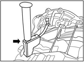
18.2 disassemble
 1. Remove the engine intake pipe.
2. Remove the battery and bracket.
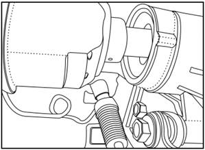
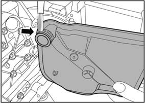
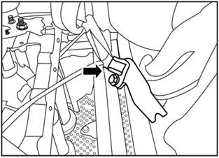
3. Remove the breather pipe.
1) Remove the clips
from the top of the breather pipe and the transmission.
2) Clamp is placed at the
connection between the shell and the breather pipe, and take down the breather
pipe.
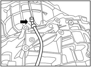
18.3 installment
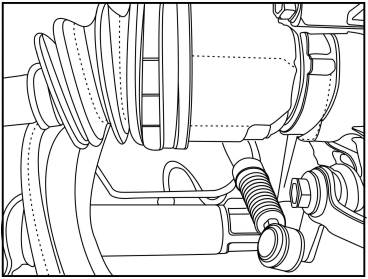
1.
Installthe breather pipe.
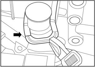
1)
Place the new breather pipe in the special tool (16G0044) and apply a little
vaseline to the aluminum tube at the bottom of the breather pipe.
2) Place the breather pipe in the
tool box on the shell and keep it parallel. Hit the tool vertically with the
rubber hammer to make the breather pipe enter into the shell.
3)
Put plastic clips 482253 on the breather pipe.
4)
Insert the pin of the plastic clasp into the hole of the metal clasp 481456.
5) Install the metal clasp firmly
on the reinforcing rib of the transmission housing.
6)
Install the breather pipe cap 483117 on the pipe, and pay attention to the
installation in place.
2.
Install the battery and bracket.
3.
Install engine intake pipe.
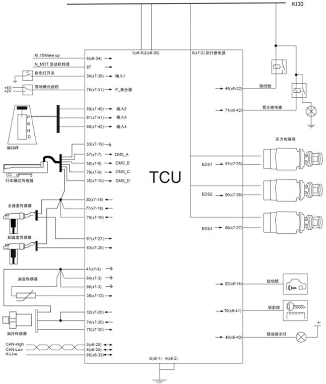
Chapter IV
Electrical Schematic Diagram
1.TCU Connector Diagram
1.1
TCU Connector
5(x7-2)
Actuator power supply
|
|
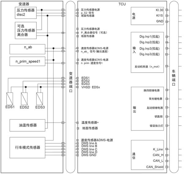
1.2 TCU and Transmission Connector
Speed
sensor&DMS-power supply
|
|
Variable
Pressure
sensor clutch
|
|
Speed
sensor&DMS-power supply
|
|
N_ab_signal
(output speed)
|
|
Speed
sensor&DMS-power supply
|
|
p_Clutch
signal (variable)
|
|
Pressure
sensor power supply
|
|
Pressure
sensor power supply
|
|
1.3Pins of
Transmission Main Connector
Connector
layout (transmission side)
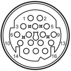
Pin distribution
|
Pin
|
Signal
|
Pin
|
Signal
|
|
1
|
Supplying valve (VHS)
|
9
|
Power supply_8,4V
|
|
2
|
EDS_1
|
10
|
P_S2
|
|
3
|
EDS_2
|
11
|
n_ab
|
|
4
|
EDS_3
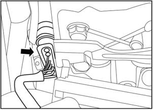
|
12
|
n_S1
|
|
5
|
Oil temperature
|
13
|
DMS_A
|
|
6
|
DMS_GND
|
14
|
DMS_B
|
|
7
|
Sensor GND
|
15
|
DMS_C
|
|
8
|
Power supply_5V
|
16
|
DMS_D
|
|
Signal
|
Instructions
|
|
DMS
|
Driving mode sensor or gear/restrain
sensor
|
|
EDS_1
|
Drive bevel gear
pressure regulator (solenoid valve)
|
|
EDS_2
|
Driven bevel gear pressure regulator
(solenoid valve)
|
|
EDS_3
|
Clutch pressure regulator (solenoid
valve)
|
|
P_S2
|
Driven bevel gear pressure sensor
|
|
N_ab
|
Driven bevel gear speed sensor
|
|
N_S1orN_Prim
|
Drive bevel gear speed sensor
|
TCU
pin distribution
|
VT3-signal
|
Pin
|
|
Always
close power supplyy Kl.30
|
1;2
|
|
Ignition
power supply Kl.15
|
6
|
|
Grounding Kl.31
|
3;4
|
|
VHSD1
(Actuator power supply)
|
5
|
|
Speed
and position sensor power supply (8.4V)
|
30; 77; 78
|
|
Pressure
sensor power supply (5V)
|
32;74
|
|
GND
Driving mode sensor
|
33
|
|
GND
sensor grounding
|
41; 64; 86
|
|
Transmission oil temperature
|
38
|
|
N_Prim
(drive bevel gear speed)
|
61
|
|
N_ab
(driven bevel gear speed)
|
63
|
|
N_MOT
(Engine speed signal)
|
87
|
|
DMS_A
(Driving mode sensor signal)
|
57
|
|
DMS_B
(Driving mode sensor signal)
|
58
|
|
DMS_C
(Driving mode sensor signal)
|
79
|
|
DMS_D
(Driving mode sensor signal)
|
35
|
|
Brake signal
|
34
|
|
Manual mode signal
|
59
|
|
Gear inceasing signal
|
81
|
|
Gear deceresing signal
|
80
|
|
P_S2
(Driven bevel gear pressure)
|
75
|
|
Snow mode
|
76
|
|
Gear shift lock
|
48
|
|
K-line
|
85
|
|
CAN-H
|
9
|
|
CAN-L
|
8
|
|
Start lock
|
92
|
|
EDS1
(Driven bevel gear pressure regulator)
|
91
|
|
EDS2
(Driven bevel gear pressure regulator)
|
90
|
|
EDS3
(Driven bevel gear pressure regulator)
|
89
|
|
Reversing lamp relay
|
71
|
2. Electronic Component Inspection List
2.1
Driving mode sensor
Check
the resistance between different pins, and judge if the driving mode sensor is
good.
DMS_GND
= pin-6
DMS_A
=pin-13 DMS_B =pin-14 DMS_C =pin-15 DMS_D =pin-16
DMS_Supply = pin-9
2.2
Corresponding Resistance Value of Each Pin
|
|
DMS_Supply
|
DMS_A
|
DMS_B
|
DMS_C
|
DMS_D
|
|
DMS_Supply
|
x
|
17.2MΩ
|
17.2MΩ
|
17.2MΩ
|
17.2MΩ
|
|
DMS_A
|
17.2MΩ
|
x
|
9KΩ
|
9KΩ
|
9KΩ
|
|
DMS_B
|
17.2MΩ
|
9KΩ
|
x
|
9KΩ
|
9KΩ
|
|
DMS_C
|
17.2MΩ
|
9KΩ
|
9KΩ
|
x
|
9KΩ
|
|
DMS_D
|
17.2MΩ
|
9KΩ
|
9KΩ
|
9KΩ
|
x
|
|
DMS_GND
|
|
4.5KΩ
|
4.5KΩ
|
4.5KΩ
|
4.5KΩ
|
2.3 Oil temperature sensor Measure
the inner resistance of oil temperature sensor. Measure the
resistance between Pin-5 and Pin-7.
When
the temperature is 20℃ to 40℃, the resistance should be 942Ω to 1121Ω.
2.4
Speed sensor
This
is a complex two-wire component, and there is no very simple way to measure
whether it works in the following range:
·
The resistance measured between Pin-9 and Pin-11 is around 24.3MΩ.
· The resistance measured between Pin-9 and Pin-12 is
around 24.3MΩ.
▲Note:
This method can not be measured to ensure that the speed sensor is well.
2.5
Oil Pressure Sensor
The
resistance measured between Pin-7 and Pin-10 is about 44.3KΩ.
2.6
Clutch Pressure Regulator
The
resistance measured between Pin-7 and Pin-10 is about 5.2Ω.
2.7
Drive Bevel Gear Pressure Regulator
The
resistance measured between Pin-1 and Pin-3 is about 5.2Ω.
2.8
Driven Bevel Gear Pressure Regulator
The
resistance measured between Pin- and Pin-2 is about 5.2Ω. TCU can’t be
detected.
▲Note:
Varying the precision of the measuring instrument will result in different
measured resistance ranges.
3.
Circuit Diagram of Transmission System
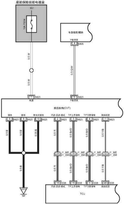
TCU1
Front
compartment fuse relay box
|
|
To P-CAN
bus communication system
|
|
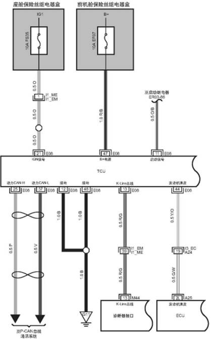
TCU2
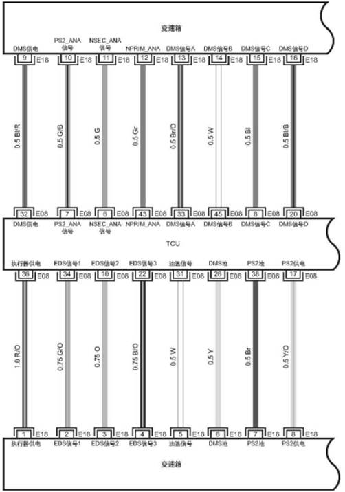
TCU3
4.
Adaptive Update
4.1
System description
Adaptive
learning is required in the following situations:
·
Refresh the TCU software
·
Replace the transmission
· Replace the TCU The clutch needs
to be adaptively renewed (self-learning) to compensate for tolerances in the
production process in order to achieve this function
by shifting gears at idle. Before
the self-learning is completed, the TCU fault indicator flashes every 2
seconds. Once the first self-learning is complete, it is automatic throughout
the life cycle.
4.2
Demand Condition
This
condition needs to be completed before self-learning:
· Engine torque and speed are
required to be stable at idle. Self-learning of the engine is also required to
be completed in advance. For more information about self-learning of the
engine, please read the document provided by the ECU supplier.
·
Engine speed requirement: ECU target value ±200rpm.
·
Engine torque demand: ECU target value ±12N·m
·
Transmission temperature should be between 30 ℃ to 80 ℃.
·
The A/C is turned off.
·
An unadaptive TCU will keep making request to the engine for idling up to
1150rpm.
If TCU has done self-learning
before, this includes: 1. Refresh the software; 2. Replace transmission TCU,
first need to delete the self-learning value. This can be done with MLT
software, or with a factory tester.
4.3
Program
When
we have fulfilled all the conditions, we will perform the following operations:
·
Vehicle speed =0kph.
·
Not step accelerator pedal.
·
Step on the brake pedal during the whole process.
·
Shift gear to "D" gear.
Yes: The
time to complete the adaption is about 40s.
|
|
Clutch
self-adapting succeed
|
|
Self-learning
period T1>120s
|
|
Ensure if
the engine temperature is above 60°C, the transmission temperature is 30°C
to 80°C
|
|
Delete
the TCU self-learning value
|
|
Wait or
drive until the temperature is within the specified range
|
|
Carry out
roller high speed test
|
|
Keep the
brake pedal during the whole process
|
|
Start
core EOL program timer T1=0:
Timer
starts to start
|
|
Do the
followings:
· Vehicle
speed = 0 kph
· Not
step accelerator pedal
· Press
the brake pedal
· The A/C
is turned off
· Shift
gear to "D" gear
|
|
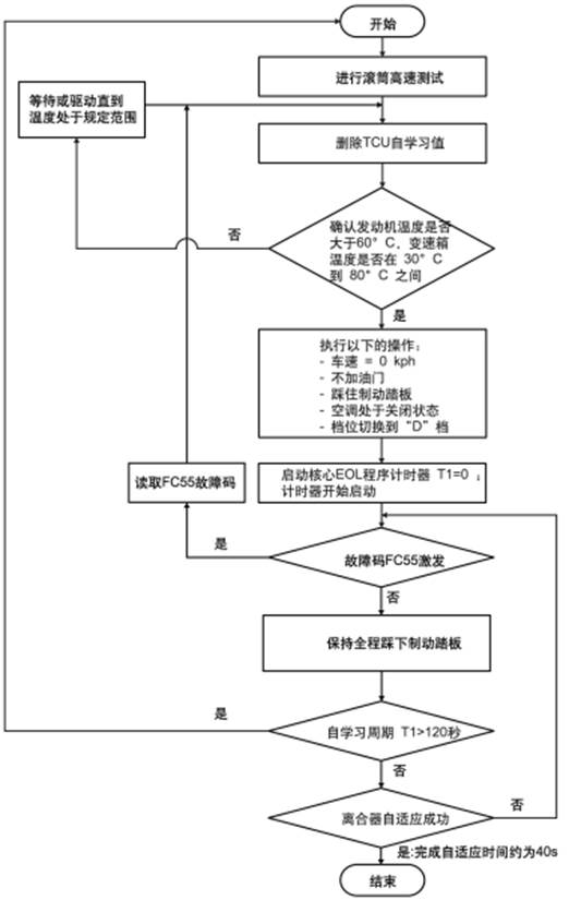
The
clutch adaptive program will start automatically. In the learning process, if
there is interference adaptive condition, the fault code FC55(P1774) will be
activated, and then the fault lamp will be on all the time as a warning. As
long as the clutch self-learning is not completed, the fault code FC51(P080A)
will be activated. At the same time, the fault lamp will keep flashing.
When everything is
running smoothly, the adaptive time at the end of the gear is about 40s. If the
adaption is not completed within 120s, the adaption will fail.
Clutch
self-adapting succeed
|
|
Self-learning
period T1>120s
|
|
Ensure if
the engine temperature is above 60°C, the transmission temperature is 30°C
to 80°C
|
|
Wait or
drive until the temperature is within the specified range
|
|
Start
core EOL program timer T1=0:
Timer
starts to start
|
|
Do the
followings:
· Vehicle
speed = 0 kph
· Not
step accelerator pedal
· Press
the brake pedal
· The A/C
is turned off
· Shift
gear to "D" gear
|
|
Keep the
brake pedal during the whole process
|
|
Yes: The
time to complete the adaption is about 40s.
|
|

When the clutch adapts
in this gear, the engine speed will rise to 1500rpm in a short time, at which
time we can proceed to the next step.
Note:
For the whole vehicle in the aftermarket, no high-speed test of the roller is
required. Be sure to check again if all the self-learning prerequisites have
been completed.
Please
follow the steps below:
·
Vehicle speed = 0 kph
·
Release the accelerator pedal
·
Keep the brake pedal during the whole process
· The off-line clutch adapts to
start automatically. In the learning process, if there is interference adaptive
condition, the fault code
FC55(P1774)
will be activated, and then the fault light will be on all the time as a
warning. As long as the clutch self-learning is not completed, the fault code
FC51(P080A) will be activated. At the same time, the fault lamp will keep
flashing. When the adaption is running smoothly, the time to complete the
adaption is about 40s. If the adaption is not completed within 120s, the
adaption will fail. If the clutch adapts successfully, the engine speed will
rise to 1500rpm in a short time and then suddenly drop to idle speed (850rpm),
at which time the gearbox fault indicator will automatically go out.
Note: first in D gear
and then in R gear self-learning, the order is not mandatory. Also, first in R
gear and then into D gear, such an adaptive order, is no problem.
5. Common Problems
|
Clutch
self-learning Fault code
|
Items
|
|
1
|
Engine
torque not steady
|
|
2
|
A/C
already in open state
|
|
4
|
Pressure
too high
|
|
8
|
Engine
speed too low
|
|
16
|
Engine
speed too high
|
|
32
|
Invalid
times too frequent
|
|
Problem
|
Possible
reasons
|
Solution
|
|
Over
120s self-learning fail
|
In the
process of learning, the transmission oil temperature is below 30 ℃
|
Start
the engine, wait for after the oil temperature rise above 30 ℃, self learning
again
|
|
In the
process of learning, the transmission oil temperature is higher than 80 ℃
|
Close
the engine, wait for after the oil temperature down to under 80 ℃, self
learning again
|
|
In the
learning process, engine temperature is below 60 ℃
|
Start
the engine, wait for after the oil temperature rise above 60℃, self learning
again
|
|
The
brake pedal was loose during the learning process
|
Re-self-learning
to make sure the brake pedal be pressed during the whole process
|
|
FC55:
the offline adaptive fault code is 1
|
Engine
torque not steady
|
Steadily
increase engine torque to ensure successful self-learning
|
|
FC55:
clutch self-learning fault code is 2
|
The A/C
is on
|
Turn
off the A/C and start self-learning again
|
|
FC55:
The offline adaptive fault code is 4
|
Clutch
pressure increased, but engine torque did not
|
Put the
gear in D or R, check whether the transmission torque is normal, check to
make sure the engine torque signal is normal, and re-self-learning
|
|
FC55:
The offline adaptive fault code is 8
|
Engine
speed too low
|
Steady
increase engine speed, re-self-learning
|
|
FC55:
The offline adaptive fault code is 16
|
Engine
speed too high
|
Steady
increase engine speed, re-self-learning
|
|
FC55:
The offline adaptive fault code is 32
|
Abnormal
torque, whether the switch is started, etc
|
Confirm
that all auxiliary functions are not used, and re-self-learning after
confirmation
|
1.
Diagnostic table
Chapter
V Troubleshooting
|
No.
|
Fault
symptoms
|
Fault
analysis
|
Solutions
|
Remark
|
|
1
|
Transmission
oil pan gasket leakage
|
Oil pan
bolt damage
|
Replace
|
|
|
Oil pan
gasket
|
Replace
|
|
Oil
drainage port
|
Replace
|
|
Oil pan
assembly
|
Replace
|
|
2
|
Transmission
oil drain screw plug leakage
|
Screw
plug fixing is not well
|
Tightening
|
|
|
Oil
drain screw plug damage
|
Replace
|
|
Oil pan
assembly damage
|
Replace
|
|
3
|
Drive
bevel gear end cover leakage
|
Sealing
cover fixing is not well
|
Tightening
|
|
|
O-ring
damaged
|
Replace
|
|
Drive
bevel gear end cover damaged
|
Replace
|
|
4
|
Driven
bevel gear end cover leakage
|
Sealing
cover fixing is not well
|
Tightening
|
|
|
Sealing
cover O-ring damaged
|
Replace
|
|
Driven
bevel gear end cover assembly damaged
|
Replace
|
|
5
|
Gear
selecting lever leakage
|
Gear
selecting lever sealing gasket damaged
|
Replace
|
|
|
Input
shaft leakage
|
Input
shaft sealing gasket damaged
|
Replace
|
|
Differential
oil seal leakage
|
Oil
seal damage
|
Replace
|
|
6
|
oil
cooler pipe connector leakage
|
Pipe
fixing is not good
|
Tightening
|
|
|
oil
cooler pipe connector sealing ring damaged
|
Replace
|
|
|
Piping
damaged
|
Replace
|
|
|
7
|
In
the process of driving in D gear, the vehicle will be charged, or the vehicle
will be charged when accelerating rapidly
|
Self-learning
is not fully completed
|
relearning
|
|
|
Fill
wrong oil or there is water in the transmission
|
Replace
the transmission oil
|
|
Drive
bevel gear speed sensor damaged
|
Replace
|
|
Hydraulic
control module malfunction
|
Self-learning
again
|
|
Driven
bevel gear speed sensor damaged
|
Replace
|
|
8
|
Shift
to D gear, release the brake pedal, the vehicle is completely stationary, and
then step the accelerator pedal, waiting for the engine speed of about 2000rpm,
the vehicle suddenly rushed forward, with a greater impact
|
Check
the fault code when in cold engine state
|
Diagnosis
by fault code
|
|
|
,
check self-learning
|
Re-self-learning
again
|
|
|
There
is a problem with the brake signal. When the brake pedal is not stepped on,
the brake signal is actually in the braking state, which will lead to this
problem
|
Check
the brake signal and wiring harness
|
|
|
If
the inspections above have no problems, there may be the valve body problem
|
Replace
the valve body, and do self-learning
|
|
2.
Noise Problem Check and Maintenance
• Driven gear bevel gear sound
When the speed is 60kph to 90kph, there is obvious noise when accelerating
slowly. Release the accelerator pedal, the sound becomes smaller. Press the
accelerator pedal, the sound
becomes larger. The sound is similar to a whistle. It increases with the speed
of the vehicle and is a normal sound. It is the sound produced by the meshing
of
the
driven bevel gear and countershaft gear.
• R
Reverse gear noise
Shift to the R gear, keep the
vehicle still, a small whistle can be heard. This is the normal sound produced
when the planetary gear inside the transmission works.
•
Low speed noise
When the vehicle speed is 40km/h,
release the accelerator pedal, and when the vehicle speed drops slowly, a
whistle can be heard. This whistle is less audible and less audible than the
sound described by the driven bevel gear, which is the normal sound between the
pinion and the differential.
|
No.
|
Fault symptoms
|
Fault analysis
|
Solutions
|
Remark
|
|
1
|
the drive bevel
gear ball bearing noise, when the vehicle driving in D gear, it sends noise,
the noise is a buzzing sound, sound size and frequency increases with the
engine speed, but not with the vehicle speed.
|
When driving at a constant speed
(constant throttle valve opening, the vehicle speed is about 60km/h) in D
gear, and then in S mode, the engine speed will increase by about 500rpm in 1
to 2 seconds. In this process, the vehicle speed is basically unchanged. If
the sound rises with the engine speed, it is the sound caused by the damage
of the drive bevel gear ball bearing
|
Replace the drive bevel
gear ball bearing
|
|
|
In manual mode 4th gear, constant a
certain throttle valve opening, keep the stable vehicle speed of about
60km/h, then shift to manual 3rd gear, the engine speed will rise about
800rpm at this moment, and then change to 4th gear from 3rd gear, the engine
speed will drop about 800rpm, the entire process speed basic remains the
same, if the sound rises with the engine speed up, the sound is from drive
bevel gear ball bearing damage
|
, replace the drive bevel gear
|
|
|
ball bearing
|
|
2
|
Bearing noise inside the transmission The bearing
noise inside the transmission makes noise during the moving process of the vehicle
in D gear. The noise is a buzzing sound.
|
According to the drive bevel gear ball bearing noise
detection method, if the noise does not rise with the engine speed, but only
rises with the vehicle speed, it may be the wheel half-shaft bearing noise,
if the half-shaft bearing fault is eliminated, it is the transmission
internal bearing noise
|
It is very difficult to judge the
noise problem correctly, so before you
decide to replace the transmission parts or the entire transmission, you need
to make sure that the noise is coming from the transmission. Easily
replaceable parts of the vehicle can be replaced to determine the noise
source
|
See flow chart of internal bearing noise
in transmission
|
|
3
|
Gearbox water noise,
shift to D gear or R gear, slowly release the brake pedal, as long as the
wheels move there will be gurgling sound, if step the accelerator pedal, the
vehicle speed from 10km/h to 40km/h will have a squeak ----, continuous
sound; more than 40km/h, the sound disappear. In the beginning of the water
inlet phase, may only hear the "gurgling" sound, when accelerating,
you can not hear the "squeak ----" continuous sound. Some vehicle
may start with a jump, depending on the water level.
|
Drain oil, remove oil pan and drive bevel gear end
cover. If there is a white substance inside the drive bevel gear end cover
and the same white substance in the oil pan, it is sufficient to prove that
there is water in the transmission or that the transmission is mixed with
other
oil or liquid
|
Replace
with a new oil filter and refill the transmission oil
|
|
|
Drive
at various speeds and accelerating/decelerating speed for about 5 minutes.
"Gurgling" sound should disappear, "squeak
----" sound should be reduced
|
Release the transmission oil and refill it with new
transmission oil
|
|
"Squeak ----"
sound can be done by stall experiment to increase the clutch temperature to
solve. Shift to D gear position, press the brake pedal and accelerator
pedal If during the process, it occurs fault code P2787 clutch temperature
is too high to disconnect the clutch, this is only the transmission's
self-protection function, rather than a fault. When the failure lamp is off
automatically, you can continue to do the losing speed experience until the
noise disappears. Too much water or mixed with too much other oil, the noise
and channeling phenomenon can not be solved
|
,
Replace the
transmission
|
|
4
|
Noise in N or P
gear (noise increases with the engine speed (the noise increases when
accelerating in N gear)
|
Judge if the
sound is from engine or transmission
|
Check the oil
pump
|
|
|
If it is from transmission
|
|
Check if oil pump has any abnormal noise
|
|
If it is from
transmission, but not
|
Replace the
transmission
|
|
oil pump noise,
it may be input shaft bearing or
|
|
planet gear set
|
|
5
|
Noise in N gear (noise doesn’t increase with the
engine speed)
|
This noise is from
other parts of the vehicle and check the vehicle parts
|
It
is very difficult to judge the noise problem correctly, so before you decide
to replace the transmission parts or the entire transmission, you need to
make sure that the noise is coming from the transmission. Easily replaceable
parts of the vehicle can be replaced to determine the noise source
|
Refer
to “Noise in N or P gear” check flow chart
|
|
6
|
During driving, the vehicle rushes; when in D gear
driving, the vehicle rushes; or when accelerating rapidly, the vehicle rushes
|
Self-learning is not fully completed
|
Complete the self-learing
|
|
|
Fill wrong oil or there is water in the
transmission, leading the transmission oil go bad
|
Replace the new transmission oil
|
|
Drive bevel gear speed sensor failure
|
Replace the drive bevel gear
|
|
Hydraulic
control module (valve) failure
|
Replace the hydraulic control module
(valve body)
|
|
Driven bevel gear speed sensor failure
|
Check self-learning
|
|
7
|
The vehicle can not
start (without accelerating), shift to D gear, after releasing the brake
pedal, the vehicle completely keep still, then accelerate, wait for the
engine speed to about 2000rpm, the vehicle suddenly rushed forward, with a
greater impact
|
Check there is failure when the vehicle
is cold
|
Check self-learning
|
|
|
There
is failure in the brake signal. When there is no brake, the brake signal is
actually in the braking state, which will
lead to this
failure
|
Check
the brake signal and wiring harness
|
|
If none of the above is
found to be a problem, it may be the valve body problem
|
Replace valve body. and
do self-learning
|
Replace
the related parts
|
|
Replace
half shaft bearing
|
|
Ensure if
the noise becomes larger along with the increasing of engine speed
|
|
Replace
the drive bevel gear ball bearing
|
|
Ensure if
the noise becomes larger along with the increasing of engine speed
|
|
Check the
other bearing inside the transmission
|
|
Failure
phenomenon: bearing buzz noise (only when driving in D gear position)
|
|
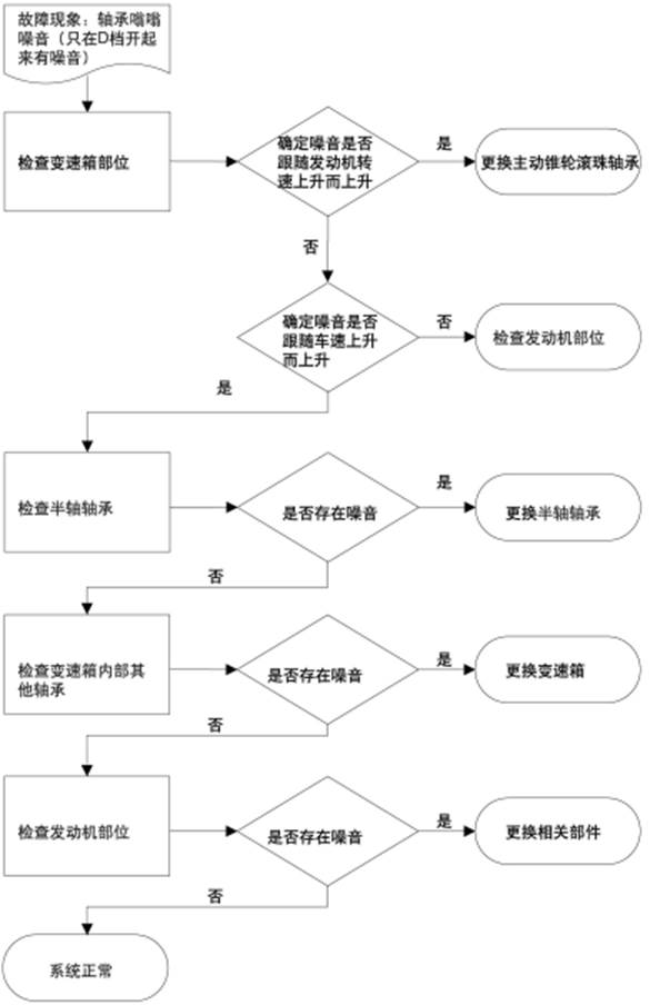
Flow chart of internal bearing
noise in transmission
Check the
planet gear or other input shaft bearing noise
|
|
Check
other parts noise in the vehicle
|
|
Ensure if
the noise becomes larger along with the increasing of engine speed
|
|
Failure
phenomenon: there is noise in N or P gear position
|
|
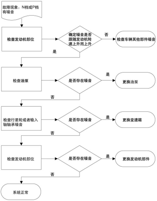
Flow chart of noise detection in N
or P gear
3. Fault code and measures
3.1
General instruction
Once
there is fault code in the transmission control unit, the failure lamp on the
instrument panel will light up. Whenever you read the DTC and find the fault
code with the diagnosis device, first check that if the fault code is
historical
fault and did not appear in the
last driving cycle. If so, delete the fault code and check that if the fault
code will appear again. If it is not the historical fault but the current
fault, follow the fault code below to solve it step by step.
Check for the latest software
every time. If not, refresh to the latest software, and then check if the fault
code still exists.
General
instructions: whenever there is a fault code or transmission problems, first
check the most basic three: a. Check whether it is special oil for CVT.
b.
Check oil level.
c. Do self-study again. There is no
need to complete all of the following procedures, and once the problem is
solved, there is no need to proceed any further.
|
No.
|
DTC code
|
TCU solution
|
Maintenance instruction
|
|
1
|
P0710 Oil
temperature sensor failure
|
Fault indicator
lamp is on, system self-set transmission oil temperature
|
Use the tester to measure the
transmission oil temperature. If the signal data is suitable, clear the fault
code and check whether it will appear again.
|
|
Check the
circuit (open circuit, short circuit, grounding).
|
|
Measuring the resistance between the two
pins of transmission main connector (when at 20 ℃, the resistance should be
980-1000Ω) to determine whether the oil temperature sensor is damaged, if
there is damage, jump to the next step and change main connector directly
|
|
Replace it with a good TCU
|
|
Replace the transmission
|
|
No.
|
DTC code
|
TCU solution
|
Maintenance
instruction
|
|
2
|
P2765
Drive bevel gear speed sensor failure
|
All
three pressure regulators are power off, fault indicator lamp is on
|
Use the tester to
measure the transmission oil temperature. If the signal data is suitable,
clear the fault code and check whether it will appear again
|
|
Check the circuit
(open circuit, short circuit, grounding).
|
|
Replace it with a
good TCU
|
|
Replace the speed
sensor
|
|
3
|
P0720
Driven bevel gear speed sensor failure
|
Fault
indicator lamp is on, system self-set driven bevel gear speed
|
Use the tester to
measure the transmission oil temperature. If the signal data is suitable,
clear the fault code and check whether it will appear again
|
|
Check the
circuit (open circuit, short circuit, grounding).
|
|
Replace it
with a good TCU
|
|
Replace the
speed sensor
|
|
4
|
P0840
Driven bevel gear pressure sensor
|
All
three pressure regulators are power off, fault indicator lamp is on
|
Use the tester to
measure the actual oil pressure of the driven bevel gear and then compare
it with the target value. If the signal data is appropriate, clear the
fault code and check whether it will appear again
|
|
According
to the value in the first step, check the circuit (grounding: 0bar
(actual pressure), short circuit: 60bar; open circuit 60bar)
|
|
Replace it with a
good TCU
|
|
Replace the valve
body.
|
|
|
:
|
No.
|
DTC code
|
TCU solution
|
Maintenance instruction
|
|
5
|
P0641 Pressure sensor
power supply failure
|
All three pressure
regulators are power off, fault indicator lamp is on
|
Use the detector to measure whether the input
voltage is 5V, and if the data is correct, clear the fault code and detect
whether it appears again
|
|
Measure the voltage
between the power supply wire and the grounding wire of the pressure sensor,
based on the results in the first step
|
|
Check the circuit (open circuit, short
circuit, grounding).
|
|
Replace it with a good TCU
|
|
Replace the
hydraulic control module (valve) failure
|
|
6
|
P0651 Driving mode sensor and speed sensor power
supply failure
|
All three pressure
regulators are power off, fault indicator lamp is on
|
Use the detector to measure whether the input
voltage is 8.4V, and if the data is correct, clear the fault code and detect
whether it appears again
|
|
Measure the voltage
between the power supply wire and the grounding wire of the pressure sensor,
based on the results in the first step
|
|
Check the circuit (open circuit, short
circuit, grounding).
|
|
Replace it with a good TCU
|
|
7
|
P0659
Pressure regulator short circuit
|
All
three pressure regulators are power off, fault indicator lamp is on
|
Measure HS
voltage and compare with battery voltage
|
|
If the same, test the
circuit (whether there is a short circuit between the battery anode and the
VHS and gearbox interfaces) and repair the wiring harness
|
|
If it is different and higher than 3.4V,
replace the TCU
|
|
No.
|
DTC code
|
TCU solution
|
Maintenance instruction
|
|
8
|
P0658
Pressure regulator open circuit or grounding
|
All
three pressure regulators are power off, fault indicator lamp is on
|
Measure HS voltage and compare with
battery voltage
|
|
If
the battery voltage is normal and the high end voltage is less than 3.4V, it
indicates that there is circuit wire grounding
|
|
If
the battery voltage is normal and the high end voltage is greater than 3.4V,
it indicates that there is open circuit
|
|
In both cases, check the pin wire according to the
specific situation, and replace the TCU if the wire is found intact after the
inspection
|
|
If the battery voltage is abnormal,
check the battery
|
|
9
|
P0702 TCU inner
check system malfunction
|
All three pressure
regulators are power off, fault indicator lamp is on
|
Replace TCU
|
|
10
|
P0962 EDS1 Drive
bevel
gear pressure regulator grounding
|
All three pressure
regulators are power off, fault indicator lamp is on
|
Measure
the resistance of the drive bevel gear pressure regulator - should be at
5.05Ω±6%
|
|
Check the wiring
(grounding) and replace the transmission internal wiring harness or engine
wiring harness according to the inspection result
|
|
Replace the hydraulic control module
|
|
11
|
P0963 EDS1 Drive
bevel
gear pressure regulator short circuit
|
All
three pressure regulators are power off, fault indicator lamp is on
|
Measure the resistance of the drive
bevel gear pressure regulator
|
|
Check
the wiring (open circuit) and replace the transmission internal wiring
harness or engine wiring harness according to the inspection result
|
|
Replace the
hydraulic control module
|
|
No.
|
DTC code
|
TCU solution
|
Maintenance instruction
|
|
12
|
P0966 EDS2
Driven
bevel
gear pressure regulator grounding
|
All three pressure
regulators are power off, fault indicator lamp is on
|
Measure the resistance of the driven
bevel gear pressure regulator
|
|
Check
the wiring (grounding) and replace the transmission internal wiring harness
or engine wiring harness according to the inspection result
|
|
Replace the hydraulic control module
|
|
13
|
P0967 EDS2 Driven
bevel
gear pressure regulator short circuit
|
All three pressure
regulators are power off, fault indicator lamp is on
|
Measure the
resistance of the driven bevel gear pressure regulator
|
|
Check
the wiring (short circuit) and replace the transmission internal wiring
harness or engine wiring harness according to the inspection result
|
|
Replace the hydraulic control module
|
|
14
|
P0964 EDS2
Driven
bevel
gear pressure regulator open circuit
|
All three pressure
regulators are power off, fault indicator lamp is on
|
Measure the resistance of the driven
bevel gear pressure regulator
|
|
Check
the wiring (open circuit) and replace the transmission internal wiring
harness or engine wiring harness according to the inspection result
|
|
Replace the hydraulic control module
|
|
15
|
P0902 EDS3 Clutch
pressure regulator grounding
|
All
three pressure regulators are power off, fault indicator lamp is on
|
Measure the resistance of the clutch
pressure regulator
|
|
Check the wiring (grounding)
and replace the transmission internal wiring harness or engine wiring harness
according to the inspection result
|
|
Replace the hydraulic control module
|
|
16
|
P0903 EDS3 Clutch
Pressure
regulator short circuit
|
All
three pressure regulators are power off, fault indicator lamp is on
|
Measure the resistance of the clutch
pressure regulator
|
|
Check
the wiring (short circuit) and replace the transmission internal wiring
harness or engine wiring harness according to the inspection result
|
|
Replace the
hydraulic control module
|
|
No.
|
DTC code
|
TCU solution
|
Maintenance instruction
|
|
17
|
P1763
Start lock grounding or open circuit
|
All
three pressure regulators are power off, fault indicator lamp is on
|
Check the wire, if the
gear sensor has failure, sometimes it may has this fault code
|
|
Replace TCU
|
|
18
|
P1764 Start lock short
circuit
|
All three pressure
regulators are power off, fault indicator lamp is on
|
Check the wire
|
|
Replace TCU
|
|
19
|
P1768 Reversing lamp
grounding
|
All three pressure
regulators are power off, fault indicator lamp is on
|
Check the wire
|
|
Replace TCU
|
|
20
|
P1769 Reversing lamp
short circuit or open circuit
|
All three pressure
regulators are power off, fault indicator lamp is on
|
Check the wire
|
|
Replace TCU
|
|
21
|
P0868 Pressure
pre-tension regulating failure
|
All three pressure
regulators are power off, fault indicator lamp is on
|
Check the oil level and the oil quality
|
|
Replace the oil pump
|
|
Replace the hydraulic control module
|
|
Replace the transmission
|
|
22
|
P0811 Clutch
(forward
or backward) slipping
|
The
failure indicating lamp is on, the clutch is open
|
Do
self-learning again, this fault code may occur in the cold vehicle state, so
do self-learning in the cold vehicle state
|
|
Check oil level
and oil type
|
|
Replace the
hydraulic control module
|
|
Replace the
transmission
|
|
No.
|
DTC code
|
TCU solution
|
Maintenance instruction
|
|
23
|
P0730
Transmission ratio control failure
|
All
three pressure regulators are power off, fault indicator lamp is on
|
Use the detector to check the signal given by the
speed sensor, and check the input current and feedback current of the drive
bevel gear pressure regulator
|
|
According to the fault to take the corresponding
measures, such as the speed sensor has a problem to check the speed sensor,
pressure has a problem to check the pressure sensor
|
|
Check oil level and oil type
|
|
Replace the oil pump
|
|
Replace the hydraulic control module
|
|
Replace the transmission
|
|
24
|
Driven bevel gear
pressure is too low
|
All three pressure
regulators are power off, fault indicator lamp is on
|
Measure actual pressure
to compare with the target during dynamic driving conditions (like manual
shift, etc.)
|
|
Check oil level and oil type
|
|
Fully complete
self-learning (fault codes may occur in the condition of self-learning
uncompletion)
|
|
Check the causes of engine torque reduction at the
engine end: spark plug, throttle, ternary catalysis, etc. (the longer the
engine is used, the more likely this problem will occur)
|
|
Replace the hydraulic control module
|
|
Replace the oil pump
|
|
Replace the transmission
|
|
No.
|
DTC code
|
TCU solution
|
Maintenance instruction
|
|
25
|
P1766 Driven bevel gear
pressure too high
|
Failure indicating lamp is on
|
Measure actual pressure
to compare with the target during dynamic driving conditions (like manual
shift, etc.)
|
|
Check oil level
and oil type
|
|
Replace the
hydraulic control module
|
|
Replace the oil
pump
|
|
Replace the transmission
|
|
26
|
P0701 Two failure occur at the same time,require
pressure regulator power off
|
Failure indicating lamp is on
|
Check other fault code
|
|
27
|
P0218 Transmission oil
temperature is too high
|
Failure indicating lamp is on
|
Check the oil cooler
|
|
Try to have this failure occur again under normal
driving condition. If not, ask the customer under what driving condition this
failure occurred
|
|
In the driving
condition of step 2, the transmission oil temperature can be measured, can
use the detector to detect whether the transmission oil temperature
≥120
℃ (if the time of occurring the fault code is shorter than 30 minutes, it is
wrong) take measures to prevent the transmission temperature too high
|
|
No.
|
DTC code
|
TCU solution
|
Maintenance
instruction
|
|
28
|
P1767
Transmission oil temperature exceeds standard range
|
All
three pressure regulators are power off, fault indicator lamp is on
|
Try to have this failure occur again
under normal driving condition. If not, ask the customer under what
driving condition this failure occurred
|
|
Check the oil
cooler
|
|
Adjust or add the
oil
|
|
Replace the valve
body.
|
|
Replace the
transmission
|
|
29
|
P0219
Power system speed exceeds the range
|
All three
pressure regulators are power off, fault indicator lamp is on
|
Never occur in
principle
|
|
Check if the
engine speed is limited within 6000rpm
|
|
30
|
P2766 Drive bevel
gear speed is not accord with the actual speed
|
All
three pressure regulators are power off, fault indicator lamp is on
|
Use the
detector to detect if other speed information (engine speed, output shaft
speed, vehicle speed) is also lost; If so, fix these problems first and
then check if the failure occurs again
|
|
Use the detector to detect the drive
bevel gear speed signal. The difference between the engine speed and the
clutch speed should be within 200rpm. All comparisons should be made
within the low to high speed range of the engine (up to 6000rpm).
|
|
Check the circuit
|
|
Replace it with a
good TCU
|
|
Check the position of the sensor,
the angle, and the speed sensor panel as well. Check if there is object
in front of the sensor (steel strip debris, etc.) Note: this is a
mechanical fault, electrical fault has other fault code
|
|
Replace the drive
bevel gear speed sensor
|
|
Replace the
transmission inner wiring harness
|
|
|
;
)
|
No.
|
DTC code
|
TCU solution
|
Maintenance
instruction
|
|
|
|
|
Replace the engine
wiring harness
|
|
Replace the
transmission
|
|
31
|
P0721 Driven bevel
gear speed is not accord with the real speed
|
The
fault indicator lamp is on. Increase the clamping force to the level of
0, system self-set driven bevel gear
|
Use the
detector to detect whether other speed information (engine speed
|
|
, output shaft
speed, speed) is also lost.
|
|
If so, solve these
problems first,then check whether
|
|
the failure will
occur again
|
|
Use detector
to detect the speed signal of the drive bevel gear, when the clutch
|
|
is meshing, compare
to the engine speed, the
|
|
difference should
be less than 200rpm. All comparisons should be made within the low
|
|
to high speed range
of the engine (up to 6000rpm).
|
|
Check the
circuit
|
|
Replace it
with a good TCU
|
|
Check the
position of the sensor, the angle, and the speed sensor panel
|
|
as well. Check if
there is any object in front
|
|
of the sensor
(pieces of steel belt, etc.)
Note: This is a mechanical
|
|
fault, the
electrical fault has other fault codes
|
|
Replace the
drive bevel gear speed sensor
|
|
Replace the
transmission inner wiring harness
|
|
Replace the
engine wiring harness
|
|
|
;
)
|
No.
|
DTC code
|
TCU solution
|
Maintenance
instruction
|
|
|
|
|
Replace the transmission
|
|
32
|
P0944
Clamping force insufficient (VSM)
|
The fault indicator
lamp is on. Increase the clamping force to the level of 0, system
self-set driven bevel gear
|
Check ECU fault
code
|
|
Replace ECU
|
|
Check the oil level
and oil quality
|
|
Fully
complete self-learning (this fault code may occur if the self-learning is
not fully completed)
|
|
Check the causes of
engine torque reduction at the engine end: spark plug, throttle, ternary
catalysis, etc. (the longer the engine is used, the more likely this
problem will occur)
|
|
Replace the valve
body.
|
|
Replace the oil
pump
|
|
Replace the
transmission
|
|
33
|
P0782 Winter
driving mode failure
|
The fault
indicator lamp is on, system self-set winter mode close
|
Check the circuit
|
|
Replace ECU
|
|
34
|
P0783
Cruise control failure
|
The fault
indicator lamp is on, system self-set cruise control function is closed
|
Check the circuit
|
|
Replace ECU
|
|
Replace TCU
|
|
35
|
P0810
Offline adaptive updating not complete
|
The fault
indicator lamp twinkles
|
Do adaptive
updating again
|
|
36
|
P1762
Current value is fixed, can’t change
|
All
three pressure regulators are power off, fault indicator lamp is on
|
Check
and remove the fault code P0962, P0963, P0960, P0966, P0967, P0964,
P0902, P0903, P0900, P1763,
P1764, and there
may be no fault code
|
|
|
.
|
No.
|
DTC code
|
TCU solution
|
Maintenance instruction
|
|
|
|
|
Fault Code
|
|
Replace it with a good TCU
|
|
37
|
P0882 Battery or high
end voltage too low
|
All three pressure
regulators are power off, fault indicator lamp is on
|
When this happens, there is a record of the
battery's current voltage (so you can tell if it is caused by battery or high
voltage); if not history record, check next step directly
|
|
Use
the detector to detect the high voltage or battery voltage - temperature has
a great influence on the value: please refer to the software for details
|
|
Check
the circuit from the battery to the TCU (fuse, main relay)
|
|
Replace/check the battery
|
|
If
it is high voltage problem: check the circuit from the transmission to the
TCU
|
|
Replace TCU
|
|
38
|
P0883 Battery or high
end voltage too high
|
All three pressure
regulators are power off, fault indicator lamp is on
|
When this happens, there is a record of the
battery's current voltage (so you can tell if it is caused by battery or high
voltage); if not history record, check next step directly
|
|
Use the detector
to detect the high voltage or battery voltage - temperature has a great
influence on the value: please refer to the software for details
|
|
Check
the circuit from the battery to the TCU (fuse, main relay)
|
|
Check/Replace the battery or generator
|
|
No.
|
DTC code
|
TCU solution
|
Maintenance instruction
|
|
|
|
|
If it is high
voltage problem: check the circuit from the transmission to the TCU
|
|
Replace TCU
|
|
39
|
P2787 Clutch
temperature is too high
|
The failure indicating
lamp is on, the clutch is open
|
Check
how many times this failure occurred, if only once or a few times, look at
the internal TCU data at that time and ask the customer about the special
driving environment at that time, such as the climbing driving, then you can
delete the fault code
|
|
Check the oil level and oil quality
|
|
Fully complete
self-learning (if the self-learning is not fully completed, this fault code
may appear)
|
|
The fault code
can only appear when the stall test is done. Delete the fault code and see if
there is any fault code
|
|
Replace TCU
|
|
It could be that the throttle valve is stuck.
Replace the throttle valve
|
|
40
|
P0727
From the ECU to
TCU
hardwire engine speed signal transmission is inconsistent with the real speed
|
Failure
indicating lamp is on
|
Check the engine
test report to see if there is engine failure, and if so, repair the engine
|
|
Check TCU input
signal - this is a frequency signal (900rpm is 30Hz, 3000rpm is 100Hz)
|
|
Replace TCU
|
|
Replace the engine speed sensor
|
|
42
|
P1761
Pressure regulator circuit failure
|
All
three pressure regulators are power off, fault indicator lamp is on
|
Use the detector
to detect the pressure decreasing inside the pressure regulator and compare
it to the specified current of each pressure regulator
|
|
Use the detector
to detect the current of the pressure regulator and compare it with the
specified current. If one of the current is found to be different from the
specified
|
|
No.
|
DTC code
|
TCU solution
|
Maintenance instruction
|
|
|
|
|
current, check
the wire of the pressure regulator (also check the inside of the
transmission).
|
|
Replace TCU
|
|
Replace the hydraulic control module
|
|
Replace the transmission inner wiring
harness
|
|
Replace the engine wiring harness
|
|
43
|
U0301 Vehicle configuration failure (such as use
other vehicle ECU)
|
All
three pressure regulators are power off, fault indicator lamp is on
|
Check whether the combination of TCU
hardware and software is correct and effective
|
|
If
it is EMS or TCU new brush software: the software on the new controller must
be wrong (the incompatibility between the transmission controller and the
engine controller)
|
|
44
|
P0706
Driving mode sensor single wire failure
|
The
fault indicating lamp is on, the system self-set sensor position
|
Use
the detector to check that if there is something wrong with the wire, what is
the problem, such as short circuit in line B, etc. (this fault indicates that
one of the wires is faulty)
|
|
Check the wiring between the
transmission and TCU
|
|
Replace it with a good TCU
|
|
Replace the driving mode sensor
|
|
Replace the transmission inner wiring
harness
|
|
Replace the engine wiring harness
|
|
45
|
P0706 Driving mode
sensor multi wire failure
|
All three pressure
regulators are power off, fault indicator lamp is on
|
Use
the detector to check that if there is something wrong with the wire, what is
the problem, such as short circuit in line B, etc. (this fault indicates that
one of the wires is faulty)
|
|
Check the wiring between the
transmission and TCU
|
|
No.
|
DTC code
|
TCU solution
|
Maintenance instruction
|
|
|
|
|
Replace it with a good TCU
|
|
Replace the driving mode sensor
|
|
Replace the transmission inner wiring
harness
|
|
Replace the engine wiring harness
|
|
46
|
P0571
Brake signal failure
|
The
fault indicating lamp is on, brake signal combined
|
Use the detector to check the state of
brake signal
|
|
Check the brake signal circuit
|
|
Check the brake switch
|
|
Replace TCU
|
|
47
|
P0955
Manual increasing/decreasing gear signal fault
|
The
fault indicating lamp is on, no manual mode
|
Check the circuit between TCU and gear
shifting
|
|
Replace the gear shift mechanism
|
|
Replace it with a good TCU
|
|
48
|
U0001 CAN bus
failure
|
The
fault indicating lamp is on, activate the emergency mode, no manual mode;
increase the clamping force level 1 (highest), the system self-set lock and
the rotating condition, activate the internal driving strategy, system
self-set the engine speed, the system self-set the engine torque, the system
self-set engine coolant temperature, brake signal combines, accelerator pedal
digital is fixed, the system self-set the left front wheel speed, the system
self-set the right front wheel speed, the system self-set
|
If this fault occurs in all other controllers, it is
wiring harness problem (CAN-H and CAN-L speed short circuit) : check the
vehicle wiring harness
|
|
If the fault is stored
only in the TCU: replace a good TCU
|
|
No.
|
DTC code
|
TCU solution
|
Maintenance instruction
|
|
|
|
the left rear
wheel speed, the system self-set the right rear wheel speed.
|
|
|
49
|
U0121 ABS
communication fault
|
CAN
|
Failure indicating lamp is on, emergency
|
Check
the CAN communication connector on the ABS controller (perhaps this fault
will be reported on other controllers)
|
|
mode is activated, no manual
|
|
mode add clamping torque level
|
|
0, system
self-set lock and rotation condition, system self-set left
front wheel speed, system self-set
|
|
right front wheel speed, system self-set
|
|
left rear wheel speed, system
|
|
self-set right rear wheel speed
|
|
50
|
U0100 ECU
communication fault
|
CAN
|
Failure indicating lamp is on, active
emergency
mode, no manual
|
Check
the CAN communication connector on the ABS controller (perhaps this fault
will be reported on other controllers)
|
|
mode add clamping torque horizontal
|
|
0,
active inner driving strategy, system self-set engine
torque,
system self-set engine
|
|
coolant temperature, accelerator pedal
|
|
value is fixed, stop at
|
|
data transmitting on CAN
|
|
51
|
U1012 CAN bus
Engine
speed signal failure
|
The system
self-set the engine speed
|
Check MCU controller (Engine
speed sensor and sensor grounding wire)
|
|
52
|
U1013 CAN bus
accelerator
pedal signal failure
|
The
failure indicating lamp is on, the accelerator pedal value is fixed
|
Check
EMS controller (Accelerator pedal sensor and sensor power supply wire)
|
|
No.
|
DTC code
|
TCU solution
|
Maintenance
instruction
|
|
53
|
U1014
CAN bus
|
failure
indicating lamp is on, active
|
Check
EMS controller
|
|
Note: All three pressure
regulators are power off: when there is fault code and the pressure regulators
are power off, clutch is open, the vehicle can’t
go even shift gear, only when the engine is missfire, the key is pulled
out and ignit again, at this time,
the vehicle can
go. Increase clamping force level
0: driven gear pressure is fixed
bevel.
The pressure is higher than
the normal condition, and is lower than the highest level
Increase clamping force level
1: driven bevel gear pressure is fixed at the highest level
|
|
EDS1: Drive bevel gear
pressure regulator
|
|
EDS2: Driven bevel gear
pressure regulator
|
|
EDS3: Clutch pressure
regulator
|
|
Emergency mode: also called
claudication home mode, when there is the following conditions, it is
activated:
|
|
CAN bus wire is loosened
|
|
emergency
mode, no manual
|
CAN ECU communication failure
|
|
Engine
torque signal
|
Mode
activates the inner driving strategy
|
CAN engine torque signal
fault
|
|
failure
|
, system self-set
the engine
|
All signals related to engine
and ABS will be replaced (apply safe measure):
|
|
Torque
|
Throttle valve opening is
fixed
|
|
Engine MAP instead of engine
torque
|
|
The engine coolant
temperature is fixed
|
|
The wheel speed is replaced
by the speed of the transmission output shaft
|
|
Engine speed signal is
transmitted by a filer
|
|
Clutch opens or combines
relatively rigid, as if no calibration data is inside
|
|
The maximum engine speed is
limited to 3200rpm
|
|
The maximum speed is limited
to 98km/h
|
|
The transmission will shift
gear in only one acceleration strategy
|
|
The CVT will only work under
the most basic conditions, providing enough drivability to get the
vehicle to the station
nearby
maintenance
|
|
After 2 seconds, manual gear
or sport gear are not in use, and the failure lamp is on
|
|
|
|
|
,
,
Chapter
I Outline and instruction
1. Outline
●Main usage and
application range
MF622D35 transmission is used to equipped
with 1.5T engine horizontally installed and front drive. The transmission is
suitable for the J7 with 1.5T engine.
●Applicable working condition and environment
The
transmission can adapt to various working conditions and working environment of
the vehicle equipped with 1.5T engine.
●Structure type and main
technical parameter 1. Structure type
All synchromesh manually shifted
mechanical transmission has flexible gear shifting, good manipulation, low
noise, compact structure, large payload and good airtightness. All gears are
normally engaged transmission of helical gears, shift gears of single cone and
triple cone synchronizer, shift gears are controlled by soft cable, structure
drawing of assembly is as follows:

1. Differential assembly
2. Reversing shaft assembly
3. Countershaft assembly
4. Input shaft assembly
5. Hydraulic separating bearing
6. Right transmission body
7. Left transmission body
2. Main
technical parameter
|
Torque
capacity
|
210
N·m
|
|
Type
|
Manual
operation
|
|
Drive
mode
|
Transverse
front wheel drive
|
|
Gear
of shifting
|
6
forward gears, 1 reversing gear
|
|
Transmission
ratio
|
1st gear/3.545, 2nd gear/2.105, 3rd gear/1.345, 4th
gear/0.971, 5th gear/0.744, 6th gear/0.630, reverse gear/3.455, main
reducer/4.462
|
|
Clutch
control
|
Hydraulic
type
|
|
Weight
(kg)
|
42
(without oil)
|
|
Lubricating oil specification
|
SAE 75W-85 (MTF-10)
|
|
Filling
method
|
Fill from oil filling plug hole (the
highest oil plug)
|
|
Lubricating oil level
|
Lower surface of oil level plug hole
(the middle oil plug)
|
|
Lubricant oil filling volume
|
1.95±0.05L
|
1.1
Transportation and storage
1.
Transmission should be rust proof, to ensure that the transmission in the
normal transport and storage will not rust.
2.
Transmission before transport should be packaged and sealed on the shelf after
fastening, shelves should ensure that in normal transport, the transmission
will not damage.
3.
The transmission shall be stored in a ventilated and dry warehouse and shall be
kept in good packing condition.
4. Under
the condition of keeping the transmission in good condition, the storage period
shall not exceed half a year.
5.
After the transmission is assembled in the engine, it should be loaded into the
whole vehicle as soon as possible to avoid the aging of oil seal lip caused by
the long transmission exposure in the air.
6. When the transmission is loaded
on the vehicle, the special lubricating oil for the transmission shall be added
according to the regulations, and the internal parts of the transmission shall
be fully lubricated before being sold out of the factory.
1.2 Usage
1.
The proper suggested figures of the speed per hour for each forward gear are as
follows:
|
Gear
|
Vehicle
speed (km/h)
|
|
1st
gear
|
0~15
|
|
2nd
gear
|
15~30
|
|
3rd
gear
|
30~40
|
|
4th
gear
|
40~60
|
|
5th
gear
|
60~75
|
|
6th
gear
|
75~100
|
▲Notes:
a. Transmission shift operation should be carried out within the speed range.
b. When the transmission is matched with different vehicles, the speed suitable
for each gear is different.
2.
Gear shifting principle
a. The gear shifting principles
while forwarding are as follows: speedup from 1st-6th gear grade by grade;
speed-down from 6th to 1st grade by grade. Reverse gear mustn’t be selected
while forwarding.
Note:
To prevent the maloperation of gear shifting, the transmission has locking
device that does not allow 6th gear to reverse gear. b. When shifting to R
gear, it requires the vehicle to be in static state. In order to avoid abnormal
sound when reversing,
it is required to wait for about 3
seconds after fully pressing the clutch pedal, and then shift to R gear. It’s
forbidden to shift to R gear when in driving forward state; meanwhile, don’t
shift to forward gears while reversing.
▲Note: When the vehicle is running,
the transmission shifting principle may not be obeyed in an emergency. 3.
Operation
By
controlling the lever in the cab, the selector lever and the shift lever can be
finally manipulated for shifting operation. Indicate the corresponding
locations of different gear shifting and selecting according to the different
directions the control rod knob indicates. The control lever will automatically
return to neutral position after each gear shifting; you can select gear only
if it returns to neutral; when gear shifting, fully press the release pedal to
enable the transmission to come off the engine’s torsion and control the shift
lever. Low speed gear shall be selected while starting.
a.
Low speed gear shall be selected while climbing up and down and turning.
Taxiing with clutch disengaged is not allowed.
b.
When it becomes difficult to control the shift rod, parking shall be done to
check the reasons without too much thrust.
1.3. Maintenance
1. For the initial maintenance,
after the transmission is running-in, the first warranty does not need to
replace the new transmission oil; then do regular maintenance. Its maintenance
should be in the vehicle special maintenance station.
2. Regular maintenance: replace
mileage: check every 30000km or 3 years (supplement or
replace if necessary), replace every 100000km or 5 years;
Replace
period: check every 3 years (if necessary add or replace), replace every 5
years.
▲Note:
B: replace transmission oil when necessary for maintenance inspection; H:
replace the transmission oil; a. The maintenance period shall be based on the
odometer reading or the number of months, whichever is reached first.
b. Suitable for various
driving conditions (repeated short distance driving; driving on uneven or muddy
roads; driving on dusty roads; driving on extremely cold or saline roads; a
short, repetitive drive in extremely cold weather).
c.
Replace transmission oil when necessary for maintenance inspection.
d. For other
maintenance operations but not oil replacement, when lifting the vehicle,
should also check whether the transmission leaks oil. 3. Maintenance and
troubleshooting under the condition of the vehicle;
4.
During maintenance, check the transmission oil as follows:
a.
Confirm whether the vehicle is in horizontal state to check the oil level.
b.
Check the transmission for oil leakage. If so, repair the leaking part. See the
maintenance manual for the repair method. c. Remove the oil filling
screw plug.
d.
Check the oil level. The oil level can be roughly checked through the oil
filling hole, that is, remove the oil filling screw plug, if the transmission
oil flows out from the oil inlet hole, or the oil level can be seen to reach
the oil inlet hole, the oil level is normal. Otherwise, should add the
transmission oil until to the oil inlet hole. 5. During maintenance, replace
the transmission oil as follows:
a.
Before replacing the oil, the engine must stop and lift the vehicle
horizontally.
b.
Under the condition of lifting the vehicle, check the oil level and whether
there is oil leakage. If there is oil leakage, deal with it.
c.
Remove the oil screw plug, discharge the waste oil, and add the specified new
oil according to the specified oil quantity (add it to the oil level hole). d.
Oil drain screw plug is coated with sealant and tighten it according to the
specified torque.
1. Fastener specification
Chapter
II Specification
|
Application
|
Specification
|
|
Separating bearing installation bolt
|
10.2~13.8 N·m
|
|
Transmission
assembly bolt
|
18~28 N·m
|
|
Reversing lamp switch assembly
installation bolt
|
7~10
N·m
|
|
Neutral signal sensor installation bolt
|
5~8
N·m
|
|
Oil
inlet screw plug
|
12~18 N·m
|
|
Oil
drain screw plug
|
12~18 N·m
|
|
Gear
shifting transmission bolt
|
18~28 N·m
|
|
Cable bracket bolt
|
19~25 N·m
|
|
Differential
bolt
|
80~100 N·m
|
|
Tighten
screw sleeve
|
121~129 N·m
|
1.1 Manual transmission
specification
1.1.1 Function-Manual
transmission
|
Application
|
Specification
|
|
Final
drive ratio
|
4.462
|
|
1st
gear transmission ratio
|
3.545
|
|
2nd
gear transmission ratio
|
2.105
|
|
3rd
gear transmission ratio
|
1.345
|
|
4th
gear transmission ratio
|
0.971
|
|
5th
gear transmission ratio
|
0.744
|
|
6th
gear transmission ratio
|
0.630
|
|
Reversing
gear transmission ratio
|
3.455
|
|
Transmission oil volume
|
1.95±0.05L
|
|
Transmission type
|
Manual
MF622D35
|
2.
Component locating diagram
2.1.
Input shaft assembly
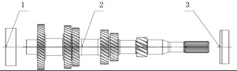
|
No.
|
Parts name
|
Code
|
Quantity
|
Remark
|
|
1
|
Input shaft left bearing
|
1709401-MF622C01
|
1
|
|
|
2
|
Input shaft assembly
|
1701110-MF622D35
|
1
|
|
|
3
|
Main shaft front bearing
|
1709406-MR513B01
|
1
|
|
2.2 Countershaft assembly

|
No.
|
Parts
name
|
Code
|
Quantity
|
Remark
|
|
1
|
Countershaft
right bearing inner ring
|
1709412-MF622C01
|
1
|
Need to
purchase with bearing outer ring
(1709410-MF622D01)
|
|
2
|
Countershaft
|
1701131-MF622D01
|
1
|
|
|
3
|
Tighten
screw sleeve
|
1709301-MF515B01
|
1
|
|
|
4
|
Countershaft
left bearing inner ring
|
1709422-MF622C01
|
1
|
Need to
purchase with bearing outer ring
(1709420-MF622D01)
|
|
5
|
Countershaft
6th gear assembly
|
1701360-MF622C01
|
1
|
|
|
6
|
5th/6th
gear synchronizer stop ring
|
1709505-MF620C11
|
1
|
|
|
7
|
Single
cone synchronizer ring
|
1701432-MF618A01
|
2
|
|
|
8
|
5th/6th
gear synchronizer assembly
|
1700406-MF618A01
|
1
|
|
|
9
|
Countershaft
5th gear assembly
|
1701350-MF622C01
|
1
|
|
|
10
|
2nd/3rd
gear clamp ring 1
|
1709503-MF622D01
|
4
|
|
|
11
|
4th/5th
gear clamp ring 2
|
1709504-MF620C11
|
2
|
|
|
12
|
Countershaft
4th gear assembly
|
1701340-MF622D11
|
1
|
|
|
13
|
3rd/4th
gear synchronizer stop ring
|
1709502-MF620C11
|
3
|
|
|
14
|
Double
cone synchronizer gear ring assembly
|
1700603-MF622C01
|
2
|
|
|
15
|
1st/2nd
gear synchronizer assembly
|
1700405-MF622C01
|
2
|
|
|
16
|
Countershaft
3rd gear assembly
|
1701330-MF622D11
|
1
|
|
|
17
|
Countershaft
2rd gear assembly
|
1701320-MF622D11
|
1
|
|
|
18
|
1st/2nd gear
synchronizer gear ring
assembly
|
1700601-MF622C01
|
2
|
|
|
19
|
1st
gear needle bearing
|
1709451-MF622C01
|
1
|
|
|
20
|
Countershaft
1st gear assembly
|
1701310-MF622D11
|
1
|
|
|
21
|
Countershaft
1st gear gasket
|
1709229-MF618A01
|
1
|
|
2.3 Differential assembly
|
No.
|
Parts name
|
Code
|
Quantity
|
Remark
|
|
1
|
Differential bearing inner ring
|
1709432-MF622D01
|
2
|
Need to purchase
with bearing outer ring (1709430-MF622D01)
|
|
2
|
Differential assembly
|
2303310-MF622D13
|
1
|
|
2.4. Reversing shaft assembly

|
No.
|
Parts name
|
Code
|
Quantity
|
Remark
|
|
1
|
Reversing
gear shaft
|
1701511-MF622D01
|
1
|
|
|
2
|
Deep groove ball bearing
|
09306204A
|
1
|
Reversing gear left bearing
|
|
3
|
High speed synchronizer clamp ring
|
1709522-MR510A01
|
1
|
|
|
4
|
R gear synchronizer assembly
|
1700407-MF618A01
|
1
|
|
|
5
|
Double cone synchronizer gear ring
assembly
|
1700603-MF618A01
|
1
|
|
|
6
|
Reversing gear idling gear
|
1701561-MF622D11
|
1
|
|
|
7
|
1st gear needle bearing
|
1709451-MF515A01
|
1
|
|
|
8
|
Reversing shaft reversing gear gasket
|
1709229-MF622D01
|
1
|
|
|
9
|
Input shaft front bearing
|
1709401-MR623B01
|
1
|
Reversing gear right bearing
|
2.5
Transmission body assembly
|
No.
|
Part
No.
|
Part
Name
|
Quantity
|
Remark
|
|
1
|
0904060025F7
|
Hex
flange bolt
|
2
|
Separating
bearing mounting bolt
|
|
2
|
1706265-MF622A01
|
Hydraulic
separation bearings
|
1
|
|
|
3
|
0904080040F7
|
Hex
flange bolt
|
20
|
Transmission
assembly bolt
|
|
4
|
1709812-MF513A01
|
Transmission
connecting pin
|
2
|
|
|
5
|
1709161-MF514M01
|
Differential
oil seal
|
2
|
|
|
6
|
1709803-MF626A01
|
Transmission
assembly pin
|
2
|
|
|
7
|
1709551-MF513A01
|
Magnet
|
1
|
|
|
8
|
1709431-MF622D01
|
Differential
bearing outer ring
|
2
|
Need to purchase with bearing
inner ring (1709430-MF622D01)
|
|
9
|
1709219-MF622C01
|
Differential
adjusting washer
|
1
|
|
|
10
|
1701721-MF622D11
|
Left transmission
body
|
1
|
|
|
11
|
1709905-MF626B02
|
Plug screw
|
2
|
|
|
12
|
1709904-MF622D31
|
Oil
drain screw plug
|
1
|
|
|
13
|
0904060016F7
|
Hex
flange bolt
|
1
|
Neutral
signal sensor bolt
|
|
14
|
1707110-MF618A11
|
Neutral
gear signal sensor
|
1
|
|
|
15
|
1700531-MF622D31
|
Gear
shift shaft assembly
|
1
|
|
|
16
|
0928060012
|
Cylindrical pin
|
1
|
|
|
17
|
1709711-MF626A01
|
Shift
fork shaft sleeve
|
4
|
|
|
18
|
1709208-MF622C01
|
Countershaft
adjusting gasket
|
1
|
|
|
19
|
1709421-MF622C01
|
Countershaft
left bearing outer ring
|
1
|
|
|
20
|
1701726-MF622D01
|
Countershaft
oil collecting tray
|
1
|
|
|
21
|
1709411-MF622C01
|
Countershaft
right bearing outer ring
|
1
|
|
|
22
|
1701726-MF622C01
|
Reversing
shaft oil collecting tray
|
1
|
|
|
23
|
1709110-MF620A11
|
Input
shaft oil seal
|
1
|
|
|
24
|
1706211-MF622A01
|
Air
discharging valve connection
|
1
|
|
|
25
|
1701711-MF622D11
|
Right box
|
1
|
|
|
26
|
0904080030F7
|
Hex
flange bolt
|
3
|
Cable
bracket bolt
|
|
27
|
0971080F7
|
Big
washer A class
|
3
|
|
|
28
|
1706190-MF622D11
|
Cable bracket assembly
|
1
|
|
2.6 Gear shift fork assembly
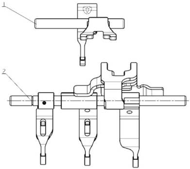
|
No.
|
Part No.
|
PartName
|
Quantity
|
Remark
|
|
1
|
1700509-MF622D01
|
Reverse gear shift fork assembly
|
1
|
|
|
2
|
1700507-MF622C01
|
Forward shift fork shaft assembly
|
1
|
|
Chapter III Diagnosis information and
operation
1. Symptom-Manual transmission
|
Symptoms
|
Operation
|
|
Cause
|
Measure
|
|
Out
of mesh
|
The
shift lever is badly worn and deformed
|
Manual
straightening shift lever; if serious bending or wear, Replace
|
|
Gear
shifting rocket arm is badly worn and deformed
|
Replace
gear shifting rocker arm in time
|
|
Gear
shifting lock ball elasticity reduced
|
Replace
gear shifting lock ball in time
|
|
Wear
and strain of shifting fork
|
Shifting
fork bending deformation can be straightened manually, but serious wear
should be
replaced
|
|
Synchronizer
gear shell, gear sleeve or gear ring abrasion
|
If
gear taking off occurs, wear parts should be replaced
|
|
After
the adjustment, the transmission did not return to
the
N gear position, or the adjustment mechanism is loose
|
Reposition
to N gear, and adjust the clearance.
|
|
Insufficient
gear shifting stroke of gear shifting tower
|
Replace
the gear shifting tower
|
|
The
connection between engine and transmission is too loose or the clearance is
not adjusted properly
|
Can
be solved by adjusting its clearance
|
|
Transmission
noise or abnormal sound
|
Insufficient
transmission oil or dirty oil
|
Fill
enough oil or replace the oil
|
|
Too
big gear axial clearance
|
Replace
the gear.
|
|
Gear
worn or gear broken
|
Replace
the gear.
|
|
Synchronizer
gear ring worn or broken
|
Replace
the gear
|
|
Bearing
damage or worn
|
Replace
the bearing
|
|
Difficult
gear shifting
|
Shift
lever or shift fork produce deformation or
uneven
wear
|
Replace
the component.
|
|
Shift
fork sleeve deformed
|
Replace
the component.
|
|
The
synchronizer ring is clamped on the gear cone
|
The
solution is to replace the gear ring
|
|
Synchronizer
slider damaged
|
Replace
the synchronizer slider
|
|
Gear
sleeve wear or ring keyway wear widen
|
Replace
relevant parts.
|
|
Oil
leakage
|
Oil
drain screw plug leak oil
|
First,
it is possible that the tightening torque of the screw plug is less than the
specified value.The second is possible with the deviation or thread tooth
damage, replace the corresponding parts
|
|
Leakage
of sealing part
|
Replace
the sealing part, and pay attention to the normative operation
|
|
Oil
leakage on transmission case joint surface
|
Check
and make the tightening torque of each connection bolt conform to the
regulations.
|
Chapter IV
Maintenance guide
1. Removal under the
vehicle
1.1 Loosen the oil drain
screw plug to drain the oil
As
shown in the figure below, loosen and remove the oil filling screw plug, the
oil level screw plug and the oil drain bolt to release the transmission oil;
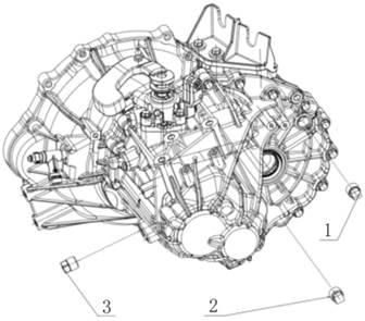
1. Oil level screw plug 2. Oil drain screw plug 3.
Oil filling screw plug
1.2
Remove hydraulic separating bearing
As shown in the figure
below, first remove the clip on the separating bearing, then pull out the air
discharging valve connector, then remove the hydraulic separating bearing bolt
(2 in total), then remove the clutch hydraulic separating bearing, and finally
remove the transmission assembly bolts in right transmission body (5 in total);

1.
Air discharging valve connector 2. Hex flange bolt (2) 3. Transmission
assembly hex flange bolt (5) 4. Hydraulic separating bearing
1.3 Remove gear shifting shaft assembly
As
shown in the figure below, first remove the gear shifting case bolts (3), then
shift to N gear, and remove the gear shifting shaft assembly
(Note:
the gear shifting shaft can be moved up and down to select the gear, namely N
gear).
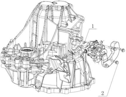
1. Gear shifting shaft assembly 2. Hexagon flange
bolt
1.4 Remove
transmission assembly bolt and disassembly
As
shown in the figure below, first remove the transmission assembly bolts (12 in
total) on the left transmission body, and then remove the left transmission
body with the transmission body separator.
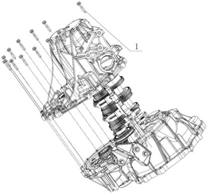
1. Hexagon flange bolt (12)
1.5
Remove left transmission body assembly
As
shown in the figure below, after removing the transmission assembly bolts (12)
on the left transmission body, take down the clip on the bolt; then remove the
neutral signal sensor bolt, take down the neutral signal sensor; remove the
left transmission body differential oil seal with the oil seal puller (Note: scrap
the oil seal, and it cannot be used again); then remove the gear shifting case
locating pin (Note: scrap and cannot be used again); turned around and
transmission body, remove the countershaft left bearing outer ring and
differential bearing outer ring with inertia hammer; finally remove the shift
fork sleeve of forward gears and reverse gear fork fork rod hole (Note: scrap
and cannot be used again).
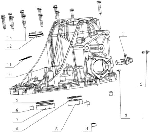
1. Neutral
signal sensor 2. Neutral sensor bolt 3. Gear shifting case locating pin 4.
Shift fork sleeve (2) 5. Counershaft left bearing outer ring 6.
Countershaft adjusting washer 7. Differential bearing outer ring 8.
Transmission assembly pin 9. Differential adjusting gasket 10. Left
transmission body 11. Clamp 12. Differential oil seal 13. Transmission
assembly bolt (12)
1.6
Remove shaft assembly, differential assembly and inner gear shifting mechanism
As shown in the figure
below, first remove the input shaft assembly, then the countershaft assembly
and the forward gear shifting fork assembly, then the reverse shaft assembly
and the reverse gear shifting fork assembly, and finally the differential
assembly.
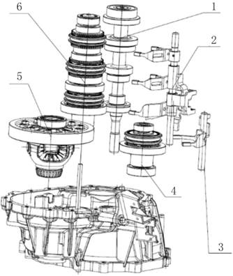
1.
Input shaft assembly 2. Forward gear shifting fork assembly 3. Reverse gear
shifting fork assembly 4. Reverse gear shaft assembly 5. Differential
assembly 6. Intermediate shaft assembly
1.7 Remove right transmission body
assembly

1.
Transmission assembly pin (2) 2. Cable bracket assembly 3. Cable bracket bolt
(3) 4. Cable bracket big washer (3) 5. Engine connecting pin (2) 6. Input
oil seal 7. Differential oil seal 8. Differential right bearing outer ring
9. Magnet 10. Countershaft right bearing outer ring 11. Countershaft oil
collecting tray 12. Reversing gear shaft oil collecting tray 13. Shift fork
sleeve (2)
1.8 Remove input shaft assembly
Use
bearing extractor to disassemble the input shaft. It can only be split into the
input shaft right bearing and the rest of the components.
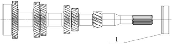
1. Input shaft right bearing
1.9 Remove countershaft assembly

1. Tighten screw sleeve
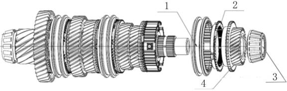
1.
5th/6th gear synchronizer gear sleeve 2. Single cone synchronizer gear ring
3. Countershaft left bearing inner ring 4. Countershaft 6th gear assembly
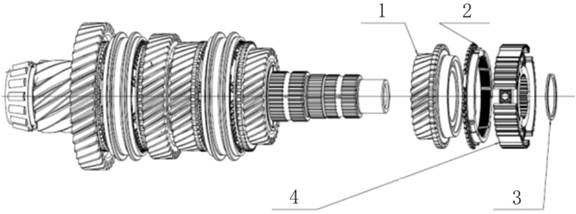
1.
Countershaft 5th gear assembly 2. Single cone synchronizer gear ring 3.
5th/6th synchronizer stop ring 4. 5th/6th synchronizer hub assembly
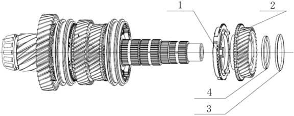
1.
Double cone synchronizer gear ring assembly 2. Countershaft 4th gear assembly
3. 2nd/3rd gear clamp ring 1 4. 4th/5th gear clamp ring 2
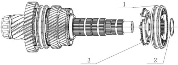
1. 1st/2nd gear synchronizer assembly 2. 3rd/4th gear
synchronizer stop ring 3. Double cone synchronizer gear ring assembly

1. 3rd/4th gear synchronizer stop ring 2.
Countershaft 3rd gear assembly
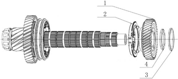
1.
Countershaft 2nd gear assembly 2. 1st/2nd gear synchronizer gear ring
assembly 3. 4th/5th gear clamp ring 2 4. 2nd/3rd gear clamp ring 1

1.
3rd/4th gear synchronizer stop ring 2. 1st/2nd gear synchronizer assembly 3.
1st/2nd gear synchronizer gear ring assembly 4. Countershaft 1st gear gasket
5.
1st gear needle bearing 6. Countershaft 1st gear assembly
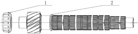
1.
Countershaft right bearing inner ring 2. Countershaft
1.10
Remove reverse shaft assembly
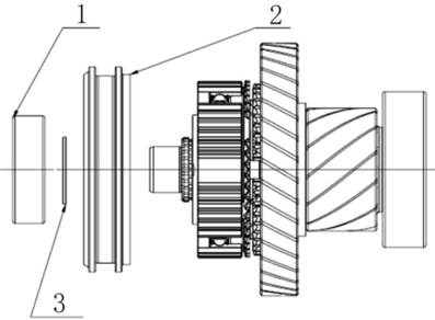
1. Reverse gear left bearing 2. R gear synchronizer
gear sleeve 3. High speed synchronizer clip ring
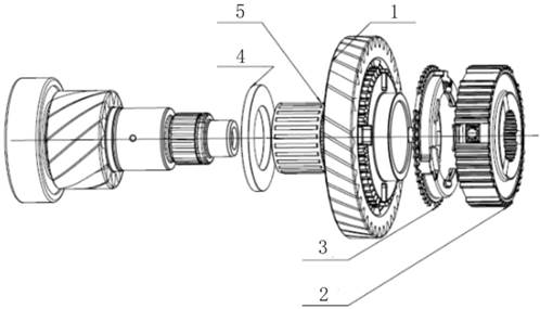
1.
Reverse gear idling gear 2. R gear synchronizer hub assembly 3. Double cone
synchronizer gear ring assembly 4. Reverse gear shaft reverse gear gasket
5. 1st gear needle bearing
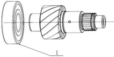
1. Reverse gear right bearing
1.11 Remove differential assembly
|

|
1. Shaft retaining ring (2)
2. Planetary gear shaft
|
|

|
1. Half shaft
gear gasket (2)
2. Half shaft gear (2)
3. Planetray gear gasket (2)
4. Planetary gear (2)
|
|

|
1. Differential
bearing inner ring
|
|

|
1. Hex flange bolt (10)
2. Main reduction gear
|
First.Cautions
Matters
needing attention before assembly:
Chapter VAssembly under the vehicle
①
Clean all parts, when assembly, please use the corresponding special auxiliary
tool, ensure the smooth assembly of each component;
② In the
relative movement of parts surface, spray gear oil;
③
Needle bearing assembly should be in the peripheral surface of the gear oil;
④ Before
the oil seal assembly, spread oil to the oil seal hole evenly;
⑤
When assembling the synchronizer, first align the synchronizer sliding block to
the sliding bolt slot on the synchronizer gear ring;
⑥ Pay
attention to the position and direction of each part;
⑦
Note: When assembling the transmission (left and right transmission body; gear
shifting case), the magnet can not be mis-installed, and has been coated with
transmission assembly glue;
⑧ Note:
when installing the input shaft assembly, the spline of the input shaft shall
not scratch the oil seal of the input shaft; otherwise, replace the oil seal of
the input shaft;
⑨ Pay attention to the assembly of
the main reduction gear and the countershaft locking screw sleeve, the screw
teeth should be evenly coated with an appropriate amount of LETAI 271 thread
fastening adhesive;
⑩
Pay attention to the tightening torque of each bolt;
2.
Assembly
2.1 Assemble right
transmission body assembly
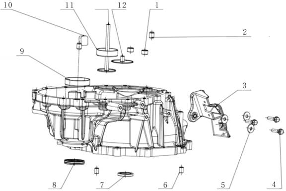
1. Shift
fork sleeve (2) 2. Transmission assembly pin (2) 3. Cable bracket assembly
4. Cable bracket bolt (3) 5. Cable bracket big washer (3) 6. Engine
connecting pin (2) 7. Input oil seal 8. Differential oil seal 9.
Differential right bearing outer ring 10. Magnet 11. Countershaft right
bearing outer ring 12. Countershaft oil collecting tray
2.2 Assemble input
shaft assembly

1.
Input shaft right bearing 2. Output shaft left bearing
2.3 Assemble countershaft assembly

1. Countershaft right bearing inner
ring 2. Countershaft
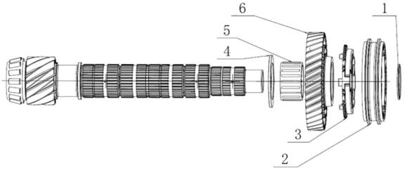
1.
3rd/4th gear synchronizer stop ring 2. 1st/2nd gear synchronizer assembly 3.
1st/2nd gear synchronizer gear ring assembly 4. Countershaft 1st gear gasket
5.
1st gear needle bearing 6. Countershaft 1st gear assembly
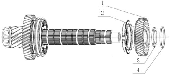
1.
Countershaft 2nd gear assembly 2. 1st/2nd gear synchronizer gear ring
assembly 3. 2nd/3rd gear clamp ring 1 4. 4th/5th gear clamp ring 2
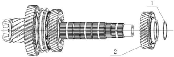
1.
3rd/4th gear synchronizer stop ring 2. Countershaft 3rd gear assembly

1.
1st/2nd gear synchronizer assembly 2. 3rd/4th gear synchronizer stop ring 3.
Double cone synchronizer gear ring assembly

1.
Double cone synchronizer gear ring assembly 2. Countershaft 4th gear assembly
3. 4th/5th gear clamp ring 2 4. 2nd/3rd gear clamp ring 1

1.
3rd/4th gear synchronizer stop ring 2. 1st/2nd gear synchronizer assembly 3.
Double cone synchronizer gear ring assembly 4. Countershaft 5th gear assembly

1.
Single cone synchronizer gear ring 2. Countershaft 6th gear assembly 3.
Countershaft left bearing inner ring
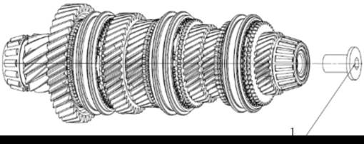
Precautions:
1.
Tighten screw sleeve
1.
In addition to pressing and installing the bearing, spread lubricating oil to
the countershaft and countershaft matched parts before each assembly step;
2.
In the last step, the locking screw sleeve needs to be coated on the thread
with LPT 7649 catalyst and LPT 272 thread fastening adhesive.
3.
At each assembly point, check whether the gear is flexible and whether the
clamp ring is in place;
2.4. Assemble reverse shaft assembly

1. Reversing left bearing
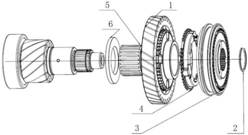
1. Reverse gear idling gear 2. High speed
synchronizer clamping ring 3. R gear synchronizer assembly 4. Double cone
synchronizer gear ring assembly 5. 1st gear needle bearing
6. Reversing shaft reversing gear gasket
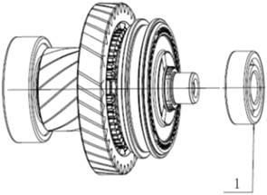
1. Reversing left bearing
Note: 1. Except for pressing and
installing the bearing, when installing, spread the lubricating oil to the
reversing shaft surface and synchronizer and gear ring matched surface;
2. At each assembly point, check
whether the gear is flexible and whether the clamp ring is in place;
2.5 Assemble differential assembly
|

|
1. Hex flange bolt (10)
2. Main
reduction gear Note: 1. This step is warm installation;
2. Before tightening the bolt, it is
necessary to spread the thread with lenten 7649 catalyst
and lenten 272 thread fastening
adhesive;
|
|

|
1. Differential bearing inner ring (2)
|
|

|
1. Half shaft
gear gasket (2)
2. Half shaft gear
(2)
3. Planetray
gear gasket (2)
4. Planetary
gear (2)
|
|

|
1. Shaft retaining ring (2)
2. Planetary
gear shaft
|
2.6 Assemble shaft
assembly, differential assembly and inner gear shifting mechanism
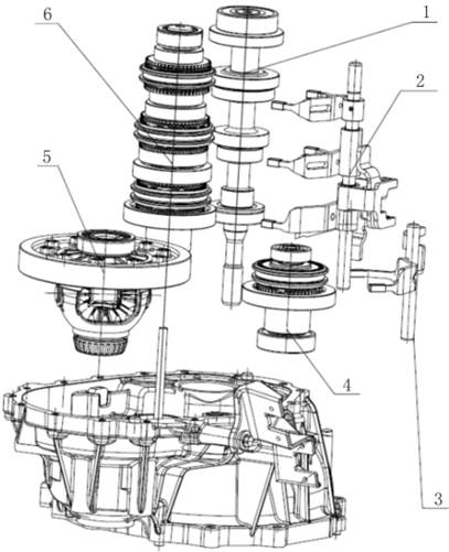
1.
Input shaft assembly 2. Forward gear shift fork assembly 3. Reversing gear
shift fork assembly 4. Reversing gear shaft assembly 5. Differential assembly
6. Countershaft
assembly After completing this step, need to measure distance between the
countershaft bearing outer ring end surface to the transmission assembly
surface of the right transmission body, the distance between the differential
bearing outer
ring end surface to the
transmission assembly surface of the right transmission body, the distance
between the left transmission body countershaft bearing hole end surface (the
end surface contact to the countershaft gasket) to the transmission assembly
surface of left transmission body, the distance between the left transmission
body countershaft bearing hole end surface (the end surface contact to the
differential gasket) to the transmission assembly surface of left transmission
body. Calculate the corresponding difference, according to the following
principles to select the appropriate countershaft gasket and differential
gasket. Selection principle of gasket:
1)
Assemble and ensure that the countershaft assembly has an interference of
0.04mm~0.11mm in the
transmission body;
2)
Assemble and ensure that the differential assembly has an interference of 0.09mm~0.16mm in the transmission body;
2.7 Assemble left
transmission body assembly

1.
Neutral signal sensor 2. Neutral sensor bolt 3. Gear shifting case locating
pin 4. Shift fork sleeve (2) 5. Countershaft left bearing outer ring 6.
Countershaft adjusting gasket 7. Differential bearing outer ring 8.
Transmission assembly pin 9. Differential adjusting gasket 10. Left
transmission body 11. Clamp 12. Differential oil seal 13. Transmission assembly
bolt (12)
2.8
Assemble left transmission body and transmission assembly bolt
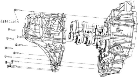
2.9.
Assemble gear shifting shaft assembly

1. Gear shifting shaft assembly 2.
Hex flange bolt (3)
2.10
Assembly the transmission assembly bolt on the right transmission body and
clutch hydraulic separating bearing
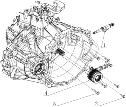
1. Air
discharging valve connector 2. Hex flange bolt (2) 3. Transmission assembly
hex flange bolt (5) 4. Hydraulic separating bearing
2.11
Assemble transmission oil drain screw plug

1. Oil level screw plug 2. Oil
drain screw plug 3. Oil filling screw plug