Cautions for electrical technicians using medical electrics
Warning:
● There is strong magnetic components on this vehicle
● If technician use medical electrics,e.g electronic pacemakers, which couldn’t be operated in the vehicle ,otherwise,the function of electrics may be effected by strong magnetic components.
Cautions for normal charge
Warning:
● If technician use the medical electrics like pacemakers, cardiovascular, in addition to the top, the machine only could be used after the function of machine checked and confirmed before normally operation.
● In the normal charging operation, Medical electrics may be affected by electromagnetic wave. When Technicians use the medical electrics like pacemakers, cardiovascular, in addition to the top etc, it is not allowed to enter into crew capsule (including luggage).
Cautions for communication equipment
● If technicians use the medical electrics like pacemakers, cardiovascular, in addition to the top etc, please keep enough distance with the communication equipment.
● Remote intelligent terminal of electromagnetic waves may affect the function of the medical electrics like pacemakers, cardiovascular, in addition to the top etc.
● If technicians use the medical electrics like pacemakers, cardiovascular, in addition to the top etc, remote intelligent terminal of electromagnetic waves may affect the function of the medical electrics. It is needed to let the manufacturer of the medial electrics confirm that the possible affection to medical electric equipment when using remote intelligent terminal .
Keypoint checking before maintenance
High pressure system can be run automatically, it is need to confirm that remote air conditioning and recharged regularly are not set before maintenance.
Cautions:
● If set remote air-conditioner or charged regularly, even though the switch is closed, high pressure system can be run automatically.
Cautions for "safety airbag"and"safety belt preloaded"of auxiliary constraint system
The combination use of "safety airbag"and"safety belt preloaded"of auxiliary constraint system and front seat belt could decrease the damage to driver and passengers when collision. The auxiliary constraint system include seat belt, airbag for driver, airbag for co-driver. The detailed information for auxiliary constraint system could refers to the sections of “airbag system” and “seat belt”
Warning:
To avoid unexpected accident, we need to obey the following:
● To avoid the auxiliary constraint system invalid, all the maintenance only could be operated by JAC authorized distributors because the risk of injury to people will be increased after invalid.
● Non-standard auxiliary constraint system of maintenance including non-standard disassembly and installation, may result in auxiliary constraint system accident triggered, causing personal injury accidents. About remove the airbag module method, please see "airbag system" section.
● In addition to the maintenance instructions in the manual operation, do not use electrical test equipment to test any circuit of auxiliary constraint system. Auxiliary constraint system of connectors and wiring harness use yellow or orange color.
Cautions when use electrical tools (pneumatic or electric)and hammer
● when electric switch in the "ON" block, near the airbag diagnostic sensors or other sensor, do not use power tools or hammer to operate sensor parts area. Severe vibration may activate the sensor, some airbags, causing serious damage.
● When using power tools or hammer, put the keys in the "LOCK" block, unplug the 12 v lead-acid battery cathode, waiting at least 1 minute, then for checking and maintenance.
Cautions for removing 12V battery
Turn the key to “on”,then to “lock” before remove 12v battery
Tip:
● Even if the key in the "LOCK" and the 12 v battery charging function may start automatically.
● After turn the key to "ON" --> "LOCK",12 v battery automatic charging will not start.
|
Name |
Diagram |
Instruction |
|
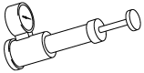
Radiator cover detector |
|
cooling system leaking detection |
|
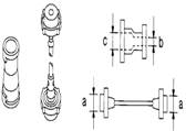
Radiator cover detector adapter |
|
Connect radiator cover detector,different radiator cover and filling mouth |
|
1 Cooling water pump bracket |
2 inlet pipe of electric charger |
3 up suspension of radiator |
|
4 Radiator assembly |
5 PCU inlet pipe PCU |
6 Radiator fan assembly |
|
7 downside suspension of radiator |
8 Inlet pipe of radiator |
9 PCU inlet pipe bracket PCU |
|
10 PCU outlet pipe |
11 Outlet pipe of radiator |
12 Cooling water pump |
Driving motor Cooling fluid direction Cooling pump Radiator assembly Charger
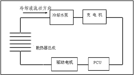
1 Check whether the cooling fluid is full, if not,please fill full. Please see “Maintenance-cooling system”
Warning:
● It is forbidden to open radiator assembly filler when the cooling fluid at high temperature to avoid overflowed coolant injury people.
2 when the key is on “ON”, use hand to touch cooling pump cover to check whether cooling pump vibrate continuously, if not, please repair or replace.
|
|
Symptoms |
Inspection item |
||
|
Cooling system parts in fault |
Poor heat dissipation |
Pump failure |
Cooling pump |
|
|
Cooling pump provide power |
|
|||
|
Radiating fan damaged |
dust or confetti jam |
|
||
|
Mechanical damage |
|
|||
|
Radiator pipe jam |
Too much foreign bodies (corrosion, dirt, sand, etc |
|
||
|
air flow is insufficient |
Cooling fan not work |
Radiator fan assembly |
|
|
|
Fan rotate with big resistance |
|
|||
|
Fan blade damage |
|
|||
|
wind cover damage |
|
|
||
|
Cooling fluid model is not correct |
|
|
||
|
poor quality of cooling liquid |
Cooling fluid viscous |
|
||
|
Cooling liquid insufficient |
Cooling liquid leaking |
Cooling fluid soft pipe |
Clamp loose |
|
|
Hose burst |
||||
|
Cooling pump |
Not well sealed |
|||
|
Radiator cover |
loose |
|||
|
Not well sealed |
||||
|
Radiator assembly |
"O" ring of water mouth damage, aging or the installation is not correct |
|||
|
temperature sensor interface damage |
||||
|
radiator assembly burst |
||||
|
Expansion kettle |
Expansion kettle broken |
|||
|
others |
Air circulation not well |
Bumper vent clogging |
|
|
|
Condenser blocked |
|
|
||
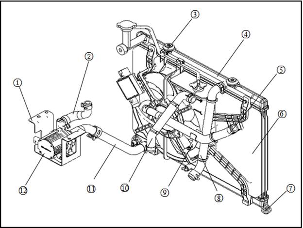
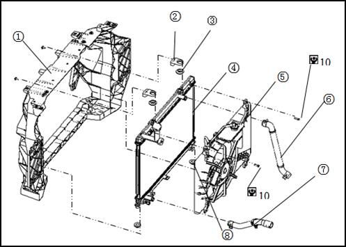
Radiator assembly, radiator fan assembly
 |
|
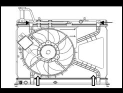
1 Front-end module assembly |
2 radiator suspension bracket |
3 Radiator upside suspension |
|
4 Radiator assembly |
5 Radiator fan assembly |
6 Radiator inlet pipe |
|
7 Radiator outlet pipe |
8 Radiator downside suspension |
|
![]() :N·m
:N·m
Warning:
● It is forbidden to open radiator cover immediately after stop the car,because cooling fluid temperature is very high, cooling fluid with high temperature may overflow from radiator filling mouth,which resulted in serious burns.
|
1 Screw off the water radiator and radiator cap, emptying coolant. |
|
|
2 Remove radiator inlet and outlet pipe |
|
|
3 Remove air-conditioner pipe connected with Condenser.please refers to “air-conditioner system- Remove and installation”. |
Caution:
● Pulling on the air conditioning pipe is prohibited.
4 Remove the radiator fan assembly and temperature sensor connector .
5 Remove front bumper.please refers to “body-body system”
6 Remove the radiator support fixed screw of the front-end module, remove the radiator assembly, radiator fan assembly.
|
7 Remove the fixed bolt of radiator assembly and radiator fan assembly , and separate the above parts.
|
|
![]() :Remove direction
:Remove direction
Check after remove
Radiator assembly
Check whether there is crack, damage or other damage in the radiator assembly surface. If yes, please remove.
Check whether the radiator fin lodging area is 2% greater than the total area. If yes, please repair or replace.
Check the water temperature sensor connector to see if there is any breakage, cracks or other damage. If yes, please replace.
Radiator fan assembly
Check whether there is crack, damage or other damage for the radiator fan assembly . If yes, please replace.
Check whether there is any breakage, cracks or other damage for the radiator fan connectors and wiring harness assembly . If yes, please replace.
Check the expansion water hose (1) whether there is ageing, cracking, or other damage. If yes, please replace the hose.
Caution:
● the scratch or damage to the radiator core body is prohibited when remove .
Install in the opposite order of remove . fill coolant, please see "maintenance - cooling system".
Check after installation
Check whether the radiator cap and bottle caps are tightened.
Check whether there is coolant leakage with the radiator cover detector.
Turn the key to “on” position, open air-conditioner in cool,check whether coolant pump and radiator fan assembly work normally.
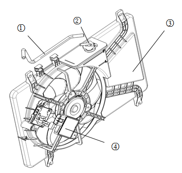
Explosion diagram
|
1 Expansion kettle hose |
2 Expansion kettle cover |
|
3 Radiator fan cover |
4 Fan controller |
Remove
1 Remove the expansion kettle hose and the kettle cover.
2 Remove the fan controller and radiator fan fixed bolt, unplug the connector, remove the fan controller.
Check after remove
Fan controller
Check whether there is a needle, curved back, breakage, cracks or other damage. If yes, please replace.
Expansion kettle hose
Check whether there is inflation kettle hose aging, cracking, or other damage. If yes, please replace the hose.
Install
Install in the opposite order of remove
|
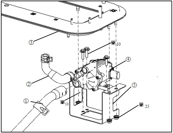
1 Radiator outlet pipe |
2 Charger inlet pipe |
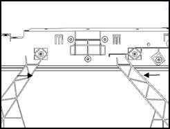
3 Power train beam |
|
4 Cooling pump |
5 Cooling pump |
|
Remove
Warning:
● It is forbidden to open radiator cover immediately after stop the car,because cooling fluid temperature is very high, cooling fluid with high temperature may overflow from radiator filling mouth,which resulted in serious burns.
1 Empty coolant. Please see the "maintenance - cooling system”.
Tip:
● Please operate when the power train assembly is in low temperature.
2 Unplug cooling pump connectors
Caution:
● To avoid hand scratches when plug connectors.
● Avoid coolant splash onto the high pressure components and connectors. If yes, please immediately wipe clean.
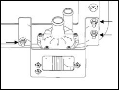
3 Remove radiator outlet pipe and charger inlet pipe.
|
4 Remove cooling pump bracket fixed nut, take out cooling pump and cooling pump bracket. |
|
● Tighten torque: 30~35N·m.
Caution:
● Avoid cooling pump falling or onslaught. If yes, please replace.
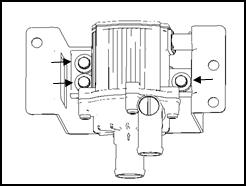
|
5 Remove fixed bolts of cooling pump and separate cooling pump and bracket. |
|
● Tighten torque:8~12N·m.
Install
Install in the opposite order of remove.
Tip:
● When installing radiator outlet pipe and charger inlet pipe, please make cooling pump steady with hand.
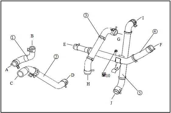
|
2 Radiator outlet pipe |
PCU outlet pipe |
||
|
5 Radiator inlet pipe |
6 Driving motor outlet pipe |
|
|
|
B Connect charger |
C connect cooling pump |
D connect radiator assembly |
|
|
F connect PCU |
G connect PCU |
H connect driving motor |
|
|
J connect driving motor |
|
|
![]() :N·m
:N·m
Maintenance data and specifications
|
Cooling fluid filling volume(L) |
≈3.1 |
|
Expansion kettle capacity(L) |
0.15 |
|
Pressure of leak detection(kPa) |
93~121 |