Cautions for electrical technicians using medical electrics
Forbidden operation
Warning:
● There is strong magnetic components on this vehicle
● If technician use medical electrics,e.g electronic pacemakers, which couldn’t be operated in the vehicle ,otherwise,the function of electrics may be effected by strong magnetic components.
Cautions for normal charge
Warning:
● If technician use the medical electrics like pacemakers, cardiovascular, in addition to the top, the machine only could be used after the function of machine checked and confirmed before normally operation.
● In the normal charging operation, Medical electrics may be affected by electromagnetic wave. When Technicians use the medical electrics like pacemakers, cardiovascular, in addition to the top etc, it is not allowed to enter into crew capsule (including luggage).
Cautions for communication equipment
● If technicians use the medical electrics like pacemakers, cardiovascular, in addition to the top etc, please keep enough distance with the communication equipment.
● Remote intelligent terminal of electromagnetic waves may affect the function of the medical electrics like pacemakers, cardiovascular, in addition to the top etc.
● If technicians use the medical electrics like pacemakers, cardiovascular, in addition to the top etc, remote intelligent terminal of electromagnetic waves may affect the function of the medical electrics. It is needed to let the manufacturer of the medial electrics confirm that the possible affection to medical electric equipment when using remote intelligent terminal .
Keypoint checking before maintenance
High pressure system can be run automatically, it is need to confirm that remote air conditioning and recharged regularly are not set before maintenance.
Cautions:
● If set remote air-conditioner or charged regularly, even though the switch is closed, high pressure system can be run automatically.
Cautions for "safety airbag"and"safety belt preloaded"of auxiliary constraint system
The combination use of "safety airbag"and"safety belt preloaded"of auxiliary constraint system and front seat belt could decrease the damage to driver and passengers when collision. The auxiliary constraint system include seat belt, airbag for driver, airbag for co-driver. The detailed information for auxiliary constraint system could refers to the sections of “airbag system” and “seat belt”
Warning:
To avoid unexpected accident, we need to obey the following:
● To avoid the auxiliary constraint system invalid, all the maintenance only could be operated by JAC authorized distributors because the risk of injury to people will be increased after invalid.
● Non-standard auxiliary constraint system of maintenance including non-standard disassembly and installation, may result in auxiliary constraint system accident triggered, causing personal injury accidents. About remove the airbag module method, please see "airbag system" section.
● In addition to the maintenance instructions in the manual operation, do not use electrical test equipment to test any circuit of auxiliary constraint system. Auxiliary constraint system of connectors and wiring harness use yellow or orange color.
Cautions when use electrical tools (pneumatic or electric)and hammer
● when electric switch in the "ON" block, near the airbag diagnostic sensors or other sensor, do not use power tools or hammer to operate sensor parts area. Severe vibration may activate the sensor, some airbags, causing serious damage.
● When using power tools or hammer, put the keys in the "LOCK" block, unplug the 12 v lead-acid battery cathode, waiting at least 1 minute, then for checking and maintenance.
Cautions for removing 12V battery
Turn the key to “on”,then to “lock” before remove 12v battery
Tip:
● Even if the key in the "LOCK" and the 12 v battery charging function may start automatically.
● After turn the key to "ON" --> "LOCK", 12 v battery automatic charging will not start.
Cautions for anti-lock braking system maintenance
● Avoid to put anti-lock braking system in strong electromagnetic field.
● ABS controller assembly shall not be placed in environment with temperature more than 105 ℃ .
● Forbid to use quick charger to disconnect the battery charging, avoid to damage the anti-lock braking system.
● Before removing the connectors of ABS controller assembly, put the key in the "LOCK" block, disconnect the battery negative electrode.
● Anti-lock braking system components couldn’t disassemble and repair.
● When anti-lock braking system is working, the brake pedal will be slight vibration, there may be mechanical noise, which belongs to the normal phenomenon.
● After the key on the "ON" block, brake pedal may vibrate or have mechanical noise in the self-check process of anti-lock braking system ,which belongs to the normal phenomenon.
● In unstable pavement, such as the top dress, sand road, snow road etc., the braking distance of the ABS activation is longer than without ABS, which belongs to the normal phenomenon.
● If the tires or friction plate is not used authentic JAC components, braking distance or steering stability may be worsen.
Special tools
The actual tool shape may be different from illustration shown.
|
Tool |
Diagram |
Instruction |
|
Diagnostic instrument X-431 |
|
ABS system fault diagnosis |
|
Tool |
Diagram |
Instruction |
|
Pipe wrench |
|
Remove and install braking lines |
|
Power tool |
|
Install and remove bolts and nuts |

Component layout

|
1 left front brake caliper assembly |
2 vacuum booster with brake master pump assembly |
|
4 Vacuum pump |
|
|
5 vacuum pump controller assembly |
6 right front brake caliper assembly |
|
7 ABS controller assembly |
8 brake pedal assembly |
|
9 brake line |
10 parking brake handle assembly |
|
11 left and right parking drawing assembly |
12 right rear parking brake assembly |
|
13 ABS wheel-speed sensor for the rear wheel assembly |
14 left rear parking brake assembly |
|
15 ABS wheel-speed sensor assembly for front wheel |
|
|
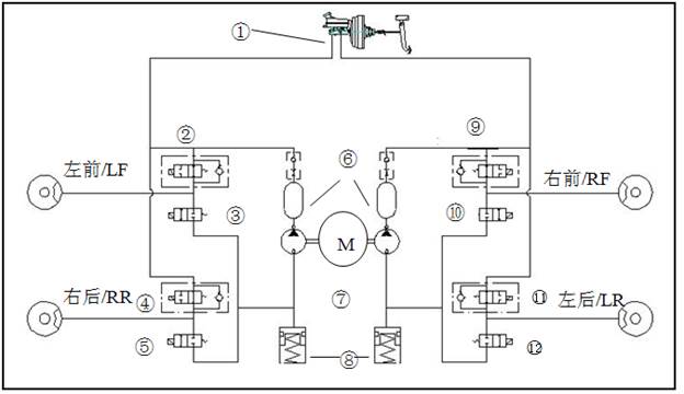
1 Brake pump |
2 Left front oil inlet valve |
3 Left front oil outlet valve |
|
4 Right rear oil inlet valve |
5 Right rear oil outlet valve |
6 Damper |
|
7 Oil returning pump |
8 Accumulator |
9 Right front oil inlet valve |
|
10 Right front oil outlet valve |
11 Lleft and right oil inlet valve |
12 Left rear oil outlet valve |
|
Fault code |
Instruction |
Fault code |
Instruction |
||
|
Decimal |
Hexadecimal |
Decimal |
Hexadecimal |
|
|
|
C190004 |
0x590004 |
ECU with too high voltage |
U000500 |
0xC00500 |
CAN with too high voltage |
|
C190104 |
0x590104 |
ECU with too low voltage |
C000700 |
0xC00700 |
CAN with too low voltage |
|
C100004 |
0x500004 |
ECU hardware fault |
C100104 |
0x500104 |
CAN hardware fault |
|
C101008 |
0x501008 |
ECU hardware fault |
C000104 |
0xC00104 |
CAN off fault |
|
C006B06 |
0x406B06 |
ABS/ESP( such as equipment) control abnormal ( surpass time) |
C100104 |
0xD00104 |
CAN Passive fault |
|
C003108 |
0x403108 |
Left front wheel speed sensor :(signal fault) out of range lost Clutter, intermittent |
C003A08 |
0x403A08 |
Right rear wheel speed sensor :(signal fault) out of range lost Clutter, intermittent |
|
C003200 |
0x403200 |
Left front wheel speed sensor:Signal lines short/open circuit, power circuit off |
C003B00 |
0x403B00 |
Right rear wheel speed sensor:Signal lines short/open circuit, power circuit off |
|
C00A000 |
0x40A00 |
Left front wheel speed sensor:power lines short |
C00A600 |
0x40A600 |
Right rear wheel speed sensor:power lines short |
|
C00A100 |
0x40A100 |
Left front wheel speed sensor:power circuit short connect with power |
C00A700 |
0x40A700 |
Right rear wheel speed sensor:power circuit short connect with power |
|
C00A900 |
0x40A900 |
Left front wheel speed sensor:normal fault |
C00AC00 |
0x40AC00 |
Right rearwheel speed sensor:normal fault |
|
C003408 |
0x4034080 |
Right front wheel speed sensor :(signal fault) out of range lost Clutter, intermittent |
C109904 |
0x509904 |
such failure of wheel speed sensor (cross of sensor and multi-sensor fault) |
|
C003500 |
0x403500 |
Right front wheel speed sensor:Signal lines short/open circuit, power circuit off |
C001004 |
0x401004 |
Valve failure, left front valvle inlet |
|
C00A200 |
0x40A200 |
Right front wheel speed sensor:power lines short |
C001104 |
0x401104 |
Valve failure, left front valvle inlet |
|
C004300 |
0x40A300 |
Right front wheel speed sensor:power circuit short connect with power |
C001404 |
0x401404 |
Valve failure, right front valvle inlet |
|
C00AA00 |
0x40AA00 |
Right front wheel speed sensor:normal fault |
C001504 |
0x401504 |
Valve failure, right front valvle inlet |
|
C003708 |
0x403708 |
Left rear wheel speed sensor :(signal fault) out of range lost Clutter, intermittent |
C001804 |
0x401804 |
Valve failure, left rear valvle inlet |
|
C003800 |
0x403800 |
Left rear wheel speed sensor :(signal fault) out of range lost Clutter, intermittent |
C001904 |
0x401904 |
Valve failure, left rear valvle inlet |
|
C00A400 |
0x40A400 |
Left rear wheel speed sensor:power lines short |
C001C04 |
0x401C04 |
Valve failure, right rear valvle inlet |
|
C00A500 |
0x40A500 |
Left rear wheel speed sensor:power circuit short connect with power |
C001D04 |
0x401D04 |
Valve failure, right rear valvle inlet |
|
C00AB00 |
0x40AB00 |
Left rear wheel speed sensor:regular fault |
C109504 |
0x509504 |
Vavle relay fault |
|
C002004 |
0x402004 |
Oil returning pump failure |
C007208 |
0x407208 |
The regular fault (over temperature protection, signal failure, hardware failure) |
|
Pin NO |
Definition |
Pin NO |
Definition |
|
1 |
Power terminal of motor (positive) |
18 |
Signal terminal of wheel speed sensor(left rear) |
|
2 |
wheel speed sensor output (right front wheel) |
19 |
Power terminal of wheel speed sensor(left front) |
|
3 |
N/A |
20 |
N/A |
|
4 |
Signal terminal of wheel speed sensor((right front) |
25 |
Power terminal of valve relay |
|
5 |
N/A |
26 |
CAN-high |
|
6 |
N/A |
27 |
N/A |
|
7 |
N/A |
28 |
ECU power supply (ignition supply line) |
|
8 |
Signal terminal of wheel speed sensor(left front) |
29 |
Signal terminal of wheel speed sensor((right rear) |
|
13 |
ground terminal of the motor |
30 |
Braking light switch input |
|
14 |
CAN- low |
31 |
Power terminal of wheel speed sensor(left rear) |
|
15 |
N/A |
32 |
N/A |
|
16 |
Power terminal of wheel speed sensor(right front) |
33 |
N/A |
|
17 |
Power terminal of wheel speed sensor(right rear) |
38 |
ECU ground line |
Anti-lock brake system include function of ABS and EBD
ABS function
In emergency braking or braking on dangerous road control hydraulic braking force of four wheels to prevent wheel lock.
ABS has following advantages:
1 Keep vehicle direction under control in the process of emergency braking.
2 Strengthen the operation for the vehicle under different road conditions.
Caution:
● When anti-lock braking system is working, the brake pedal will be slight vibration, there may be mechanical noise, which belongs to the normal phenomenon.
● If the power outage, anti-lock braking system stop working, ABS fault warning lights lit.
● When ABS function failure, ABS fault warning lights lit, only activate the EBD, no ABS function.
● Please use the special diagnostic instrument provided by JAC to diagnose ABS fault.
EBD function
Electronic brake-force distribution (EBD) automatically adjust the braking force distribution ratio of front and rear axle, increase the efficiency of the brake, and comply with ABS braking stability.
Caution:
● EBD function failure, the braking system fault warning lights and ABS fault warning lights lit at the same time, EBD and ABS function failure.
Diagnosis process

Caution:
● Shall check whether ABS is normal after the completion of the clean inspection .
● Fault code can't be cleaned up through removing ABS controller connector assembly, disconnect the battery connection or let the key in the "LOCK" block.
1 Check the brake fluid level and brake lines. Please see the "maintenance - brake fluid.
2 Check whether there is leakage for ABS controller assembly. If yes, check the following items:
① Such as ABS controller assembly pipe joints with leakage, check whether the ABS controller assembly pipe joint is loose, if loose, tighten to standard torque (16 ~ 18 n · m). If there is still leakage, check whether the brake pipe joints and ABS controller assembly thread is damaged. If yes, please replace and make sure no brake fluid leakage.
② If there is leakage outside of ABS controller assembly joint, check again after clean with cloth . If there is still leakage, please replace ABS controller assembly.
Caution:
● Forbid to disassemble ABS controller assembly.
3 Check whether there is wearing for the friction plate and brake shoe. Please see the "maintenance - brake shoe”.
4 Check whether the positive and negative battery is loose. If yes, please repair or replacement.
5 Check whether there is any mechanical fault related to the braking system of vehicles:
● Check whether there is pollution for the master cylinder brake fluid.
● Check whether there is damage for the wheel speed sensor and wiring harness, connectors, ring gear.
● Check the tires wearing degree
6 Road test vehicle
● Check for brake lag.
● Check whether the brake is stable (without backward or forward)
● Check whether the wheel bearing has abnormal noise.
Check for ABS fault warning light and brake system fault warning light
1 Turn the key to "ON" block from the "LOCK" block , ABS fault warning light and brake system fault warning lights lit. In the absence of light, please see the "ABS common symptoms and analysis".If light,go to next step.
2 After 3 seconds, check whether the ABS fault warning light and brake system fault warning light is put out. If not, go to the next step.
3 Driving vehicle for one minute at the speed of more than 30 km/h, check whether the ABS fault warning light and brake system fault warning light is put out. If not, please see the “diagnosis process”.
Confirm fault reason with diagnostic instrument
1 System instruction
Diagnostic instrument could detect problems resulted from ABS and EBD system fault, and guide maintenance technician to confirm the cause of the problem.
2 Diagnosis process
Must choose diagnostic procedures matching with the model . After all the system troubleshooting, should clear ABS fault code.
|
Steps |
Diagnosis |
Yes |
No |
|
1 |
① Connect or install all the parts disconnected or removed before. ② Install the diagnosis instrument on the connection of OBD. ③ Put the key on “ON”, check whether the diagnostic instrument could communicate with ABS controlling assembly. |
To step 2 |
To step 4 |
|
2 |
Check whether there is current or historical fault code. |
To step 3 |
To step 7 |
|
3 |
① Record the current fault code. ② Record the historical fault code. ③ Record the setting times of fault code. Tip: Before record information , do not remove the fault code. ④ Repair fault components |
|
|
|
4 |
Whether diagnostic instrument can communication with other modules of the same data line. |
To step 5 |
To step 6 |
|
5 |
See "common symptoms and analysis of ABS - ABS controller assembly without communication". |
|
|
|
6 |
Check OBD connection检查OBD接口。 |
|
|
|
7 |
① put key on “ON” block ② Waiting for 10 minutes ③ Turn the key to “ON”,and see whether ABS fault warning light is on. |
To step 8 |
To step 10 |
|
8 |
Whether the light is off after light for 3 s . |
Normal, end |
To step 9 |
|
9 |
See "common symptoms and analysis of ABS-ABS fault warning light on but without fault code” |
|
|
|
10 |
See "common symptoms and analysis of ABS-ABS fault warning light off and without fault code” |
|
|
Common symptoms and analysis of ABS
1 No communication with ABS controller assembly
Typical reasons:
● Poor contact of OBD interface
● ABS controller assembly off ground
● ABS controller assembly without voltage provided by battery.
● ABS controller assembly without voltage provided by supreme electric switch.
● Data circuit open circuit or short circuit.
● Data line with high resistance.
2 ABS fault warning light off and without fault code
Typical reasons:
● Bulbs failure of the ABS fault warning light or socket is loose.
● Fuse disconnect
● Fault of combination instrument driver module
● ABS controller assembly and combination instrument connection line is open circuit or short circuit.
3 ABS fault warning light on and without fault code
Typical reasons:
● Combination instrument cannot communicate with ABS controller assembly .
● ABS controller assembly off ground
● ABS controller assembly and combination instrument connection line is open circuit or short circuit.
● Fault of combination instrument driver module.
● Fault of ABS controller assembly ABS
4 Braking system fault warning light on
Typical reasons:
● Brake fluid level is too low or brake fluid switch with fault.
● Vacuum booster system fault.
● EBD function invalid:
① Two coaxial wheel-speed sensor failure.
② Battery open circuit or short circuit
③ ABS controller assembly ground open or short circuit
④ The electrical switch is open circuit or ground short circuit.
● Combination instrument and ABS controller assembly is open circuit.
● Combination instrument fault
● ABS controller assembly failure
5 Brake system fault warning light is off and without fault code
Typical reasons:
● Bulbs failure of the brake system fault warning light or socket is loose.
● Fuse disconnect
● Fault of combination instrument driver module
● ABS controller assembly and combination instrument connection line is open circuit or short circuit.
6 Intermittent failure or poor contact of intermittent failure
Typical reasons:
● Circuit fault
● Relay or solenoid valve binding
ABS controller assembly exhaust
Any of the following situations occurs, need exhaust:
1 Press “braking system exhaust” can not meet the requirement of the pedal height or feeling.
2 Replace ABS controller assembly.
3 Excessive loss of brake fluid.
4 Air may enter into ABS controller assembly.
Exhaust process
1 Necessary item
① Diagnostic instrument
② Brake fluid
③ lifting machine
④ Hose with exhaust gas bottle
⑤ Safety equipment, such as safety glasses
⑥ Two maintenance personnel: one on the brake pedal and diagnostic instrument operation, another person will keep the brake fluid level of tank, and open and close exhaust bolt according to the diagnostic instrument direction .
2 Basic check
① Check the power supply system. If abnormal, please repair or replacement.
② Connect diagnosis instrument, remove all fault code. If couldn’t be removed, please find fault.
③ Check whether there is any damage on appearance of ABS controller assembly and leakage. If yes, please repair or replacement.
3 Preparation before exhaust
① Brake system exhaust. Please see “maintenance-brake fluid”
② Put key on “ON” block.
③ Connect diagnosis instrument, select procedures matching with vehicle and communication with ABS controller assembly.
④ Lifting vehicle
⑤ Perform automatic exhaust based on diagnostic instrument direction.
4 Automatic exhaust
Please see the following automatic exhaust sample to complete exhaust.
Tips:
● Exhaust process could be terminated automatically by pressing the EXIT on the diagnostic instrument (EXIT) key at any time.
Automatic exhaust sample:
|
① Enter into special fault diagnosis system of JAC passenger car. |
|
|
② Select diagnosis software version matching with vehicle. |
|
|
③ Enter into automatic exhaust process. Operate according to tips. |
|
|
④ First step for exhaust Tip: ● It is necessary to step on the brake pedal and keep the brake fluid level of the tank in the process of automatic exhaust.
|
|
|
⑤ In the process of exhaust。 |
|
|
⑥ Complete the first step. |
|
|
⑦ Second step of exhaust Caution: ● When exhaust, exhaust bottle connected with exhaust pipe must be more than 30 mm higher than the exhaust bolt . |
|
|
⑧ In the process of exhaust。
|
|
|
⑨ Third step of exhaust。
|
|
|
⑩ In the process of exhaust。
|
|
|
⑪ Complete the third step。
|
|
|
⑫ Forth step of exhaust。
|
|
|
⑬ In the process of exhaust。
|
|
|
⑭ Complete the forth step。 |
|
|
⑮ The fifth step of exhaust
|
|
|
⑯ In the process of exhaust
|
|
|
⑰ Complete exhaust。
|
|


Remove
1 Front wheel speed sensor
① Lifting vehicle
② Unplug connectors
|
③ Remove fixing bolt of sensor and take out sensor slowly. ● Tightening torque:8~10N·m Caution: ● Pulling on wheel speed sensor wiring harness is prohibited. |
|
|
2 Rear wheel speed sensor ① Lifting vehicle ② Remove the column C under decorating plate, remove the sensor wiring harness connector, take off the rear wheel speed sensor. ③ Remove rear hub assembly .please see “rear axle-rear hub assembly” |
|


Caution:
● Pulling on wheel speed sensor wiring harness is prohibited.
● Rear wheel speed sensor is integrated in the wheel hub assembly, unable to disassemble.
Check after remove
Check whether there is any foreign body in the front wheel speed sensor mounting holes, presence of scrap metal and other foreign matter in ring gear surface r. If yes, please clean up.
Install
Install in the opposite order of remove and tighten the bolt to the standard torque.
Caution:
● When installing, pay attention to the clearance between the ring gear and wheel speed sensor.
Standard value: 0.2~1.1mm。
Remove
1 Closed on electric switch, disconnect the battery negative.
2 Plug out the ABS controller connector assembly.
3 Fully press down the brake pedal and fix with pedal frame.
4 Remove ABS controller assembly and braking hard pipe joint with the brake master cylinder assembly, mark it , use special-purpose plug insert ABS controller assembly line.
● Tightening torque:16~18N·m
5 Remove the brake hard pipe joint with the brake sub cylinder connected. Mark it well and plug ABS controller assembly line joint with special-purpose plug.
● Tightening torque:16~18N·m
|
6 Take off ABS controller assembly from the bracket of ABS controller . ● Tightening torque:20~25N·m
|
|

Install in the opposite order of remove.Please see “Maintenance- brake fluid”.
Caution:
● Banned to remove ABS controller assembly line interface plug before equipping brake hard tube to the ABS controller assembly.