Cautions for electrical technicians using medical electrics
Forbidden operation
Warning:
● There is strong magnetic components on this vehicle
● If technician use medical electrics,e.g electronic pacemakers, which couldn’t be operated in the vehicle ,otherwise, the function of electrics may be effected by strong magnetic components.
Cautions for normal charge
Warning:
● If technician use the medical electrics like pacemakers, cardiovascular, in addition to the top, the machine only could be used after the function of machine checked and confirmed before normally operation.
● In the normal charging operation, Medical electrics may be affected by electromagnetic wave. When Technicians use the medical electrics like pacemakers, cardiovascular, in addition to the top etc, it is not allowed to enter into crew capsule (including luggage).
Cautions for communication equipment
● If technicians use the medical electrics like pacemakers, cardiovascular, in addition to the top etc, please keep enough distance with the communication equipment.
● Remote intelligent terminal of electromagnetic waves may affect the function of the medical electrics like pacemakers, cardiovascular, in addition to the top etc.
● If technicians use the medical electrics like pacemakers, cardiovascular, in addition to the top etc, remote intelligent terminal of electromagnetic waves may affect the function of the medical electrics. It is needed to let the manufacturer of the medial electrics confirm that the possible affection to medical electric equipment when using remote intelligent terminal .
Keypoint checking before maintenance
High pressure system can be run automatically, it is need to confirm that remote air conditioning and recharged regularly are not set before maintenance.
Cautions:
● If set remote air-conditioner or charged regularly, even though the switch is closed, high pressure system can be run automatically.
Cautions for "safety airbag"and"safety belt preloaded"of auxiliary constraint system
The combination use of "safety airbag"and"safety belt preloaded"of auxiliary constraint system and front seat belt could decrease the damage to driver and passengers when collision. The auxiliary constraint system include seat belt, airbag for driver, airbag for co-driver. The detailed information for auxiliary constraint system could refers to the sections of “airbag system” and “seat belt”
Warning:
To avoid unexpected accident, we need to obey the following:
● To avoid the auxiliary constraint system invalid, all the maintenance only could be operated by JAC authorized distributors because the risk of injury to people will be increased after invalid.
● Non-standard auxiliary constraint system of maintenance including non-standard disassembly and installation, may result in auxiliary constraint system accident triggered, causing personal injury accidents. About remove the airbag module method, please see "airbag system" section.
● In addition to the maintenance instructions in the manual operation, do not use electrical test equipment to test any circuit of auxiliary constraint system. Auxiliary constraint system of connectors and wiring harness use yellow or orange color.
Cautions when use electrical tools (pneumatic or electric)and hammer
● when electric switch in the "ON" block, near the airbag diagnostic sensors or other sensor, do not use power tools or hammer to operate sensor parts area. Severe vibration may activate the sensor, some airbags, causing serious damage.
● When using power tools or hammer, put the keys in the "LOCK" block, unplug the 12 v lead-acid battery cathode, waiting at least 1 minute, then for checking and maintenance.
Cautions for removing 12V battery
Turn the key to “on”,then to “lock” before remove 12v battery
Tip:
● Even if the key in the "LOCK" and the 12 v battery charging function may start automatically.
● After turn the key to "ON" --> "LOCK", 12 v battery automatic charging will not start.
Cautions for braking system maintenance
● When find force on the brake pedal heavier or lighter, please check or adjust the braking system.
● When key in the "ON" block and vacuum pump is working, the brake pedal stroke may feel very heavy or very short, this is normal phenomenon. If braking system fault warning lights keep light in driving, please check the related parts.
● when the brake system power supply failure occurs , brake system without vacuum booster, brake force will be entirely depends on the force on the brake pedal. Combination instrument of brake system failure warning lights lit at this time.
● Please put keys in "LOCK" and ABS connectors unplug before maintenance, or disconnect the 12 v battery cathode .
● Because the dust on the front and rear brake has an effect to human body, please use clear dust collector before maintenance, blow out air gun is strictly prohibited.
● When disassembling and installing brake line , please use oil pipe wrench.
● Don't make brake fluid splash on paint surface to avoid damage the paint. If splashed on paint surface, please immediately wash with water.
● clean the brake parts with water.
● Please use the new brake fluid cleaning brake pliers or other brake system components.
● It is prohibited to use gasoline or kerosene and other mineral oil, to avoid damage to the braking system and brake control system components.
● Banning the use of liquid containing petroleum base and oil base fluid container.
● Repeated use of discharged brake fluid is prohibited.
● Check no brake fluid leakage after replacing parts.
● After repairing or replacement brake drum (dish), brake shoe, or brake soft during driving very short, be sure to running-in brake joint surface.
● Vacuum pump of flooding is prohibited.
Special maintenance tools should be used for disassembly if necessary.
Commonly used tools
|
Tool |
Diagram |
Instruction |
|
Pipe wrench |
|
Remove and install braking lines |
|
Power tool |
|
Install and remove bolts and nuts |
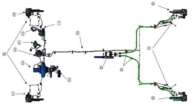
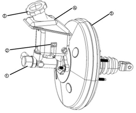
Component parts
|
1 left front braker assembly |
2 vacuum booster with brake master pump assembly |
|
3 Vacuum tank assembly |
4 Vacuum pump |
|
5 vacuum pump controller assembly |
6 right front brake caliper assembly |
|
7 ABS controller assembly |
8 Brake pedal assembly |
|
9 brake line |
10 parking brake handle assembly |
|
11 left and right parking drawing assembly |
12 right rear parking brake assembly |
|
13 ABS wheel-speed sensor for the rear wheel assembly |
14 left rear brake assembly |
|
15 ABS wheel-speed sensor assembly for front wheel |
|
|
No |
Parts |
Function |
|
1、6 |
Left and right front braker assembly |
Response of the hydraulic braking force |
|
2 |
Vacuum booster with brake master pump assembly |
Transmit pedal force and provide power,
establish hydraulic braking, detect brake liquid level and output the
combination instrument signal. Warning lights lit on the meter, when the
liquid level is too low warning light is on. |
|
3 |
Vacuum tank assembly |
Store vacuum, Detect and output vacuum degree signal to the vacuum pump controller assembly |
|
4 |
Vacuum pump |
Controlled by the vacuum pump controller assembly, vacuum |
|
5 |
Vacuum pump controller assembly |
Receive vacuum degree signal,control vacuum pump opening and closing |
|
7 |
ABS controller assembly |
Receives the brake lamp switch, wheel speed sensor signal through hard line. Output the following signals to VCU through the CAN communication: ABS working status, speed, four rounds of speed. |
|
8 |
Brake pedal assembly |
Actuation vacuum booster and provide mechanical power, detection of the pedal stroke and output brake signal to VCU. |
|
9 |
Brake line |
Pass the brake fluid and hydraulic pressure |
|
10 |
Parking brake handle assembly |
Locking or loosen parking drawing |
|
11 |
Left and right parking drawing assembly |
Passing parking handle force and stroke |
|
12、14 |
Left and right rear parking brake assembly |
Response the braking force provided by the hydraulic and parking drawing |
|
13、15 |
ABS wheel-speed sensor for front and the rear wheel assembly |
Detect wheel rotating speed and transmit wheel speed signal to the ABS controller assembly |
Diagnosis and maintenance process
Fault diagnosis process details
1 Collect customer information
Before check, carefully ask customer concerns or driving vehicles together with the customer which is very important for solving the problem.
2 Check symptom
According to the infroamtion collected through interviewing with the customer ,reappear information of customer specified symptoms. Check whether the symptoms caused by the failure mode.
Caution:
When symptoms are caused by normal operation, please fully inspect each related parts and let customers understand the symptoms are normal.
3 Repair or replace defective parts
① Repair or replace defective parts
② re-assembly and connect after repairing or replace defective parts
4 Confirm the symptoms disappear
If symptoms disappear, meaning complete the maintenance. If not, then return to step 3.
In general, customers have their own judgment standard to a problem. Therefore, careful enough to ask to understand customer's concern is very important. Preparing interview list make diagnostic information systematic. Some times, many conditions occur at the same time resulting in failure.
Interview list sample
|
Interview list |
|||||
|
Customer name |
Gender |
Plate No |
|
Original registered date |
|
|
Model |
|
VIN |
|
||
|
Production date |
|
Motor power |
|
Mileage |
km |
|
Symptom |
□no( )function |
||||
|
□( )Warning light on |
|||||
|
□noise □vibration |
|||||
|
□others( ) |
|||||
|
Firstly appear |
□recently □other( ) |
||||
|
Appearing frequency |
□always □regular □sometimes( times/day) |
||||
|
Climate condition |
|
□no relation |
|||
|
weather |
□sunny □cloudy □rainy □snow □others( ) |
||||
|
temperature |
□hot □温暖 □凉爽 □冷 □气温(大约 ℃) |
||||
|
comparative humid |
□high □normal □low |
||||
|
Road conditions |
□city road □suburb □highway □Mountain road □non-paving road |
||||
|
Operation conditions etc |
□no relation □Drive motor startup □Unload □Driving □Speedup □ drive with same speed □decrease speed □turning □steering wheel turning |
||||
|
Other conditions |
|
||||
|
Remark |
|
||||
Fault description
When press brake pedal, appear abnormal pedal feeling( such as soft or hard, etc.)
Diagnosis procedure
1 Check front and rear axle
In accordance with the "maintenance - axis and suspension", check whether the front axle loose seriously. If yes, repair or replace defective parts. If not, enter the next step.
2 Check the brake disc jumping and brake drum jumping
In accordance with the "maintenance - brake disc, brake drum" check brake disc jumping and brake drum jumping. If it is normal, enter the next step. If not, repair or replacement.
3 Check braking fluid leakage
In accordance with the "maintenance - brake fluid" check whether the brake fluid is leaking. If it is normal, enter the next step. If not, repair or replace defective parts.
4 Check the brake pedal
In accordance with the "maintenance - brake pedal" check the brake pedal. If it is normal,enter the next step. If not, adjust the pedal.
5 Check braking force
Check the brake force. If it is normal,enter the next step. If not, check each component of brake system.
6 Check brake performance
Disconnect connectors of ABS, vacuum pump, and press on the brake pedal more than five times continuously, make the ABS, vacuum booster, brake energy recovery system not work. Check whether the vehicle braking performance is normal.Restore connectors after check.
Failure description
Braking distance is long when ABS is activated.
Diagnosis procedure
Tips:
● On unstable road, such as the non-paving road, sand road, snow road, etc., the braking distance of the ABS activation can be longer than without ABS, which is the normal phenomenon.
1 Check 12V battery
When key in the "LOCK" block, check whether the battery cable is normal connected, and measure whether the battery voltage in the range of 12 ~ 12.7 V. If it is normal, enter the next step. If not, repair or replace defective parts.
2 Check vacuum booster
Check vacuum booster. If it is normal, enter into next step.if not, check each part of braking system, repair or replace defective parts.
3 Check braking force
Check braking force. If it is normal, enter the next step. If not, check each part of braking system, repair or replace defective parts.
4 Check braking performance
Disconnect connectors of ABS, vacuum pump, and press on the brake pedal more than five times continuously, make the ABS, vacuum booster, brake energy recovery system not work. Check whether the vehicle braking performance is normal.Restore connectors after check.
Failure description
Vacuum doesn’t work and failure warning light of braking system on combination instrument is always on.
Diagnosis procedure
Tips:
●Vacuum pump doesn’t work without enough vacuum degree, which is normal phenomenon.
1 Check 12V batter
When key in the "LOCK" block, check whether the battery cable is normal connected, and measure whether the battery voltage in the range of 12 ~ 12.7 V. If it is normal, enter the next step. If not, repair or replace defective parts.
2 Check vacuum booster system
Put Key on “ON”block,press braking pedal 5 times continuously and check carefully whether the vacuum pump work . If it doesn’t work, enter the next step. If work, finish the check.
3 Check vacuum tank assembly
Disconnect vacuum tank assembly pressure switch connector, pressure switch end connectors is measured with a multimeter if two terminals are conducted. If conduct,means that pressure switch is failure, replace the vacuum tank assembly, and the according to the step 2 recheck vacuum booster system. If not, connect the vacuum tank connector to the next step.
4 Check vacuum pump
Disconnect the vacuum pump connector, connect with the positive (red) wire of vacuum pump connector and battery anode with line, connect anode (black line) and battery cathode socket. If the vacuum pump does not work, replace the vacuum pump, vacuum booster reexamination and according to the step 2. If the vacuum pump work, connect the vacuum pump connector, then to the next step.
5 Check vacuum pump controller
Replace the vacuum pump controller. According to the step 2 review vacuum booster, if vacuum pump work, finish diagnosis. If the vacuum pump does not work, check the vacuum pump repair insurance and associated wiring harness, see “the electric system- grounding and circuits ”.
Vacuum pump continuous working
Failure description
When don't step on the brake pedal, the vacuum pump work continuously, could continue to hear the sound of the vacuum pump work, vacuum pump surface temperature is higher.
Diagnosis procedure
1 Check 12V batter
When key in the "LOCK" block, check whether the battery cable is normal connected, and measure whether the battery voltage in the range of 12 ~ 12.7 V. If it is normal, enter the next step. If not, repair or replace defective parts.
2 Check vacuum booster system
Put key on “ON” block, press braking pedal,check whether there is boost for braking. If yes, enter next step. If not,enter to the forth step.
3 Check vacuum tank assembly
Disconnect vacuum tank assembly pressure switch connector, pressure switch end connectors is measured with a multimeter if two terminals are conducted. If conduct,means that pressure switch is failure, replace the vacuum tank assembly, and the according to the step 2 recheck vacuum booster system. If not, connect the vacuum tank connector to the next step.
4 Check vacuum pump
Replace vacuum pump and wait for 15 s. If vacuum pump stop work, which means fault has been out and recheck vacuum booster system according to step 2. If continue to work, go to next step.
5 Check vacuum pump controller
Replace vacuum pump controller and waiting for 15s. If vacuum pump stop work, which means the failure is out and recheck vacuum booster system according to step 2,finish diagnosis.If continue to work, check vacuum booster、related harness and pipe.
When don’t step on the brake pedal, vacuum pump work frequently and automatically.
Diagnosis procedure
Tips:
● Frequent press on the brake pedal, the vacuum pump will work frequently, which is the normal phenomenon.
1 Check vacuum booster system
Put the key on “ON” block, quick and continuous press the braking pedal 5 times,waiting for 10 minutes after vacuum pump stopping work. If vacuum automatically start work, means vacuum tank assembly、vacuum hose、vacuum booster etc has air leakage.
2 Check related parts
Check the vacuum hose coupling, pipe clamp, if not well installed, please re-install.
Check whether there is hose connection wall crack, if yes, please replace the vacuum hose.
Replace the vacuum tank assembly and the re-inspection vacuum booster system, if the fault has been ruled out, finish the diagnosis. If the fault has yet to rule out, replace the vacuum booster and re-inspection vacuum booster system.
Tips:
● vacuum hose has a multilayer structure to ensure the tightness and durability, surface minor cracks will not affect the use.
Description
|
Phenomenon |
Conclusion |
|
Braking pedal may moved down when braking |
This phenomenon may mean vacuum pump work normally,not failure. |
|
When the key in the "LOCK" and step on the brake pedal, brake pedal stroke may shorten, pedal feel may harden. |
This phenomenon may be vacuum degree in the vacuum tank reduce, vacuum booster effect is abate, not failure. |
|
When the key on "ON" block, front cabin have noise, the noise suddenly disappeared over a period of time. |
This phenomenon may be the automatic stop after vacuum pump to start the work after a period of time , not failure. |
|
Step on the brake pedal in the process of vehicle driving, pedal violent vibration with cabin noise. |
This phenomenon may be ABS in regulating hydraulic braking, not failure. |
Other common troubleshooting table for braking system
|
Failure |
Possible reason |
Solution |
|
When braking, vehicles run partial to one side |
Left and right ire pressure is insufficient |
Adjust tire pressure |
|
Wheel alignment is not correct |
Wheel alignment |
|
|
Poor contact for friction plate |
Adjust friction plate |
|
|
Friction surface with grease or oil |
Replace friction plate |
|
|
Brake sub-pump assembly is not correct |
Re-assemble |
|
|
Not enough braking force |
Few brake fluid or with pollution |
Supplement or replace |
|
Air in braking system |
Exhaust |
|
|
Vacuum booster with failure |
Replace vacuum booster |
|
|
Poor contact for friction plate |
Adjust friction plate |
|
|
Friction surface with grease or oil |
Replace friction plate |
|
|
The friction drag lag cause brake rotating parts overheating. |
Repair or replace |
|
|
Braking fluid leakage |
Repair or replace |
|
|
Pedal stroke increases |
Air in braking system |
Exhaust |
|
Braking fluid leakage |
Repair or replace |
|
|
Clearance from vacuum booster push rod to brake master cylinder is too large |
Repair or replace |
|
|
Exit brake lag |
Parking brake is not completely loose |
loose |
|
Parking brake improper adjustment |
loose |
|
|
Brake master cylinder oil return port congestion |
Clean after disassembly |
|
|
Return spring of rear brake damaged |
Replace |
|
|
Insufficient lubrication for sliding parts |
lubricate |
|
|
Return spring of brake master cylinder valve or piston damaged. |
Replace brake master pump |
|
|
Clearance between vacuum booster pus hrod and brake master cylinder is too small |
Repair or replace |
|
|
Insufficient parking brake force |
Rear brake shoe damaged |
Repair or replace |
|
Rear brake shoe with grease or oil |
Replace rear brake |
|
|
Parking brake drawing stuck |
Repair or replace |
|
|
Parking lever stroke is too large |
Adjust parking lever |
|
|
Vacuum pump not work |
Vacuum pump damaged |
Replace vacuum pump |
|
Vacuum pump controller damaged |
Replace vacuum pump controller |
|
|
Vacuum tank pressure switch short-circuit or damaged |
Replace vacuum tank assembly |
|
|
Vacuum pump fuse damaged |
Replace insurance |
|
|
Related harness、connector short-circuit or break |
Repair or replace |
|
|
Vacuum continuous work |
Vacuum pump controller damaged |
Replace vacuum pump controller |
|
Vacuum tank assembly pressure switch damaged |
Replace vacuum tank assembly |
|
|
Vacuum tank assembly leakage |
Replace vacuum tank assembly |
|
|
Vacuum hose air leakage |
Repair or replace |
|
|
Vacuum pump damaged |
Replace vacuum pump |
|
|
Vacuum tank pressure switch harness break |
Repair or replace |
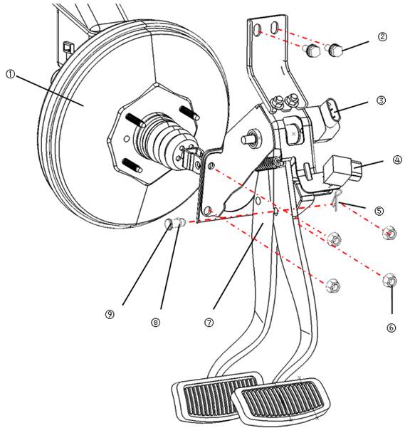
Explosion diagram
|
1 vacuum booster |
2 bolts |
3 Angle sensor |
|
4 brake lamp switch |
5 rivets |
6 hex flange surface nut |
|
7 Brake pedal assembly |
8 ring |
9 main pump pin |
Remove
|
1 Remove the lower part of the dashboard. Please see the "Body systems - interior dashboard". 2 Disconnect the brake lamp switch and angle sensor connector. 3 Remove the main pin shaft, which is connected with the vacuum booster,Disconnect the connection with vacuum booster. |
|
|
4 Remove the fixing bolt of brake pedal and body, and fixing nut with the vacuum booster. ● Tightening torque:20-25N·m 5 Take out the brake pedal assembly |
|

Check after remove
Brake pedal
● Check whether the main pump pin shaft hole has wearing deformation.
● Check whether brake pedal has cracks, deformation or other damage.
Main pump pin shaft
● Check whether the main pump pin is damaged or deformed, if yes, please replace.
Brake lamp switch
|
● Multimeter is used to inspect 2 terminals of the brake lamp switch ,when press and release the sliding column ①of brake lamp whether it is conduction. As shown in figure, when press sliding column > 4 mm, not conduction between terminals, and conduction once loose, which explain the brake lamp switch work normally. Otherwise, the brake lamp switch failure, please replace the brake lamp switch. |
|

Install
Install in the opposite order of remove
Caution:
● Check whether the brake pedal operation is smooth.
● Shall check and adjust the brake pedal free stroke after installation
● Check the clearance between the brake pedal and the brake lamp switch .
Vacuum booster with brake master pump assembly
|
1 Brake master pump |
2 Brake liquid level switch |
3 storage tank cover |
|
4 storage tank |
5 vacuum booster |
|
Caution:
● Don't let the brake fluid splashed on paint surface, otherwise it will damage the paint. If splashed on paint surface, please immediately wash with water.
Remove
|
1) ischarge the brake fluid. Please see the "maintenance - brake fluid. 2) emove the connectors connected with the brake fluid level switch. 3) emove the braking hard tube pump with pipe wrench. |
|
|
1. emove the main pump pin shaft, which is connected with the brake pedal assembly, remove the main pump pin shaft, collar, rivets. 2. emove the fixing nut of brake pedal and vacuum booster, take off the vacuum booster with brake master pump assembly. |
|

Install
Install in the opposite order of remove. Fill braking fluid and exhaust. Please see “maintenance-brake fluid”
Caution:
● Please refill brake fluid “DOT4”
● Repeated use of emitted brake fluid is prohibited.
● When install the pump pin, shall be coated with grease: SAE J310 or similar products.
Check after install
Check whether there is leakage on master pump mounting surface, liquid storage tank installation surface and brake pipe joint . If yes, repair or replacement.
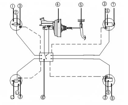
Hydraulic pipe
|
1 Right front wheel |
2 right front sub-pump |
3 wheel speed sensor |
|
4 vacuum booster with brake master pump assembly |
5 Brake pedal |
6 Right rear sub pump |
|
7 Right rear wheel |
8 left rear whee |
9 left rear sub pump |
|
10 ABS module ABS |
11 left front wheel |
12 left front sub pump |
Caution:
● All brake hose and brake pipe cannot be excessive bending, distortion and stretch.
● Confirm there is no interference for pipe with other parts when turning.
● Braking pipeline is an important safety components, if discover the brake fluid leak, must tighten. If found damaged parts, please replace.
● When broken brake pipe, please seal well open end to avoid let foreign body in .
● Be careful not let brake fluid splash on paint surface to avoid damage paint. If splashed paint on surface, please immediately wash with water.
● Please refill brake fluid “DOT4”
● Repeated use of emitted brake fluid is prohibited
Master cylinder flow-line assembly
1 Remove
① Open the engine cover
② Exhaust braking fluid , please see “maintenance-braking fluid”
③ Remove master cylinder flow-line assembly
|
1) Remove the tubing nut, release the connections between master cylinder tubing assembly and brake master cylinder. ● Tightening torque: 16~18N·m
|
|
|
2) Remove the tubing nut, release the connection of master cylinder tubing assembly and ABS/ESP controller. ● Tightening torque: 16~18N·m
|
|
|
3) Release two pipe clamps and two front tube clamps of fixed master cylinder of flow-line assembly.
|
|
Install in the opposite order of remove
Front braking pipe assembly
1 Remove
① Open the engine cover
② Exhaust braking fluid , please see “maintenance-braking fluid”
③ Remove left front braking hose assembly
|
1) Remove the connecting nut and clip of left front braking oil hose and left front braking hose, take off the connection of left front braking oil hose and left front braking hose ● Tightening torque: 16~18N·m
|
|
|
2) Remove the connecting nut of left front braking oil hose and ABS/ESP controller, remove the connection of left front braking oil hose and ABS/ESP controller. ● Tightening torque: 16~18N·m
|
|
|
2) Remove the three pipe clips for fixing left front braking oil pipe assembly. 3) Remove left front braking oil pipe assembly
|
|
④ Remove left rear connecting braking pipe assembly, right rear connecting braking pipe assembly.
|
1) Remove one oil fuse nut and clipper of which connecting with left /right connecting braing pipe ● Tightening torque: 16~18N·m
|
|
|
2) Remove the connecting nut of left/right rear braking pipe Assembly and oil hose of ABS controller, remove the connection of left/right rear braking pipe assembly and oil hose of ABS controller ● Tightening torque: 16~18N·m
|
|
|
3) Take off 2 front pipe clipper for fixing left/right rear braking pipe assembly 4) Take off left rear braking pipe assembly and right rear braking pipe assembly
|
|
|
2 Install ① Install left front braking oil pipe assembly. ② Install the connecting nut and clipper of left Front braking oil hose and left front braking hose. ● Tightening torque: 16~18N·m
|
|
|
2) Install connecting nut of left front braking oil hose and ABS/ESP controller. ● Tightening torque: 16~18N·m
|
|
|
3) Install left front braking oil hose on the 2 clippers for fixing left front braking oil hose assembly.
|
|

③ Install left rear connecting braking pipe assembly, right rear connecting braking pipe assembly,.
|
1) Install one connecting nut of left /right rear braking pipe and ABS/ESP controller. ● Tightening torque: 16~18N·m
|
|
|
2) Install one connecting nut and clipper of left /right rear braking pipe and rear part of left /right rear braking pipe. ● Tightening torque: 16~18N·m
|
|
|
3) Install left /right rear braking pipe assembly on the pipe clipper. 4) Add braking fluid. please see “maintenance-braking fluid” 5) Braking system exhaust, please see “maintenance-braking system exhaust” 6) Close engine cover.
|
|
Right front braking pipe assembly
1 Remove
① Open the engine cover
② Exhaust braking fluid , please see “maintenance-braking fluid”
④ Remove right front braking hose assembly
|
1) Remove the connecting nut and clip of right front braking oil hose and right front braking hose, take off the connection of right front braking oil hose and right front braking hose . |
|
|
2) Remove the connecting nut of right front braking oil hose and ABS/ESP controller, remove the connection of right front braking oil hose and ABS/ESP controller. 3) Take off right front braking oil pipe assembly
|
|
2 Install
① Install according to remove order of right front braking oil hose.
② Add braking fluid. please see “maintenance-braking fluid”
③ Braking system exhaust, please see “maintenance-braking system exhaust”
Rear braking pipe assembly
1. Remove
① Open the engine cover
② Exhaust braking fluid , please see “maintenance-braking fluid”
③ Remove rear wheel, please see “wheel”
④ Remove left rear braking pipe rear assembly、right rear braking pipe rear assembly
|
1) Remove connection nut of the left and right rear connect braking hard tube assembly and rear part of left and right rear brake pipe , take off the connection of left and right rear connection braking hard tube assembly and rear part of left, right rear brake pipe.
|
|
|
2) Remove the connecting nut and clipper of rear part of left and right rear brake hard tube assembly and left and right rear brake hose.
|
|
3) Take off 5 pipe clippers and one individual pipe clipper connecting rear part of left and right rear brake hard tube assembly and body
4) Take off left and right rear brake hard tube assembly
⑥ Remove connection of left rear braker hard tube assembly and right rear braker hard tube assembly.
|
1) Remove the connecting nut and clipper of left rear brake hard tube assembly and left rear brake hose II, take off connection of left rear brake hard tube assembly and left rear brake hose II.
|
|
|
2) Remove the connecting nut and clipper of left rear brake hard tube assembly and left rear brake hose, take off connection of left rear brake hard tube assembly and left rear brake hose.
|
|

3) Take off connection of left rear brake hard tube assembly and right rear brake hard tube assembly.
⑦ Remove rear brake oil hose bracket
|
1) Remove the fixing bolts of brake oil hose bracket and body. 2) Take off rear brake oil hose bracket.
|
|
2 Install
① Install according to remove order of rear brake pipe assembly.
② Add braking fluid. please see “maintenance-braking fluid”
③ Braking system exhaust, please see “maintenance-braking system exhaust”
④ Install rear wheel
Rear brake hose assembly
1. Remove
① Exhaust braking fluid , please see “maintenance-braking fluid”
② Remove rear brake hose assembly
|
7) Remove the connecting nut and clipper of rear brake hose assembly and rear part of rear brake hard tube.
|
|
|
2) Remove the connecting nut and clipper of left rear brake hose assembly and left rear brake hard tube assembly 3) Take off rear brake hose assembly.
|
|
2 Install
① Install according to remove order of rear brake hose.
② Add braking fluid. please see “maintenance-braking fluid”
③ Braking system exhaust, please see “maintenance-braking system exhaust”
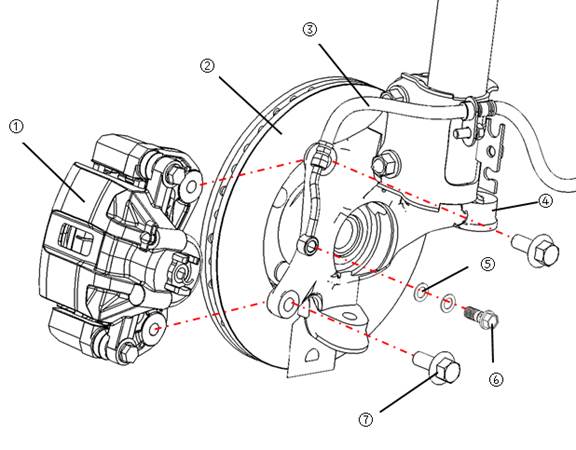
Explosion diagram
![]()
![]()
|
1 front brake pliers |
2 front brake disc |
3 front brake hose |
4 steering knuckle |
|
5 sealing washer |
6 brake hose perforation bolt |
7 hexagon flange bolts |
|
![]() :Replace after remove
:Replace after remove
![]() :N·m
:N·m
Caution:
● Should thoroughly clean the brake pliers, make damage caused by dust and other substances to a minimum.
● When remove brake pliers, forbid to press brake pedal to avoid the piston ejected.
● To avoid damage piston dust proof when remove.
● Unless dismantle or replace the brake pliers, otherwise prohibited to remove connection bolt of brake pliers and brake hose . After remove the brake pliers, please use the rope hoist brake pliers to avoid pull brake hose.
● If the friction plate and silencing slice are severely corrosion, please replace the new friction plate.
● Avoid brake fluid splash on the brake disc, if yes, please erase immediately.
Friction plate
Remove
|
1 Remove wheel, please see “Wheel” ● Tightening torque:90~110N·m 2 Remove the fixing bolt for Brake pliers locating pin ● Tightening torque:22~32N·m 3 Lift pump with rope , then remove the friction plate. |
|
|
Check after remove Check thickness of friction plate with a scale. Standard thickness: 9.5 mm Friction limit thickness:2mm |
|


Caution
● If the thickness of friction plate is less than the thickness of the wear limit, please replace friction plate
Install
1 Install friction plate on the bracket.
2 Press down piston when installing friction plate, then install sub pump on the bracket.
Tips:
● Check the brake fluid level of brake liquid storage tank, prevent overflow.
3 Install sliding pin of downside braking pliers, and tighten.
4 Fix brake disc with tire nut and press brake pedal till returning brake feeling.
5 Rotate brake disc, check whether the friction plate is installed well.
6 Install wheel.
Brake pliers
Remove
|
1 Remove wheel 2 Remove Perforated bolt of brake hose. ● Tightening torque:25~30 N·m |
|
|
3 Remove connecting bolt for brake pliers and steering knuckle , then take off brake pliers. ● Tightening torque:65~75 N·m
|
|


1 Install the brake caliper to the steering knuckle, and screw down the bolt.
Caution:
● Avoid the fixing bolt and fixing bolt pads of steering knuckle, brake caliper, brake hose to be with oil and water.
|
2 Install the brake hose to the brake caliper, and screw the bolt. |
|

Caution:
● Please refill brake fluid “DOT4”
● Reuse brake hose seal gasket is prohibited.
● Aim the brake hose and brake caliper limit and connect it.
3 Fill brake fluid and exhaust. Please see “maintenance-brake fluid”
4 Rotate brake disc, check whether brake pliers installed well.
Front brake disc
Remove
1 Remove wheel, please see “Wheel”
2 Remove front brake caliper, please see “front brake caliper assembly”
3 Remove front brake disc
|
1) Remove the ten screws on the front brake disc. ● Tightening torque : 10~15N·m 2) Take off front brake disc.
|
|
Check after remove
1 Visual inspection
Check whether the front wheel brake disc surface is uneven wear, crack and serious damage. If yes, please change.
2 Beat quantity check
|
1) Fix front wheel brake disc on wheel hub. Caution: ● Please confirm the wheel axial clearance not too big before measuring.
|
|

8) Check beat quantity with a dial indicator, which could measure on the edge of the brake disc within 10 mm.
9) Use the dial indicator check runout, the brake disc inside edge measurements 10mm
● Beat limit quantity:0.05mm
If beat quantity surpass limit, please replace brake disc or do the necessary processing.
3. Thickness check
|
1) Check the thickness of the brake disc with a micrometer. If the thickness is less than wear and tear limit, please replace the brake disc. Standard thickness: 25 mm Friction limit thickness:23mm
|
|
Install
Install in the opposite order of remove.
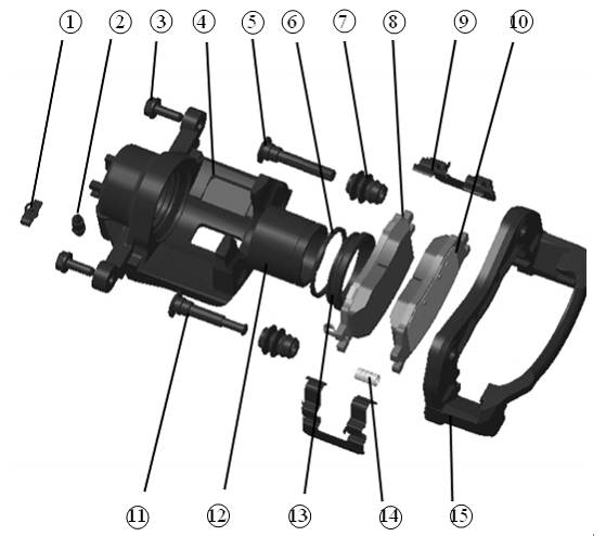
Explosion diagram
![]()
|
1 vent screw dust cover |
2 vent screw |
3 hex flang bolts |
4 pliers body |
|
5 positioning pin |
6 piston sealing ring |
7 dowel pin dust cover |
8internal friction piece |
|
9 spring leaf |
10 external friction piece |
11 guide pin |
12 piston |
|
13 piston dust cove |
14 rubber |
15 bracket |
|
![]() :Replace
after remove
:Replace
after remove
Remove
1 Remove the hex flang bolt, separate clamp body and bracket. If necessary, remove the friction piece from the bracket.
Caution:
● Avoid friction piece drop
2 Remove positioning pin、guide pin and dowel pin dust cover from bracket.
|
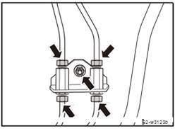
3 As show in the diagram put fitable wood,then blast to the the fixed bolt hole of brake hose evenly, remove piston and piston dust cover. Caution: ● Avoid finger to be clamped by piston
|
|
|
4 Remove the piston sealing ring from the clamp body with flat mouth screwdriver. Caution: ● Avoid to damage the clamp body inner cylinder wall.
|
|
Check after remove
1 Clamp body
Check whether the inner wall of the cylinder is worn or damaged. If yes, please replace.
Caution:
● Using the new brake fluid cleaning cylinder body. It is prohibited to use gasoline or kerosene, etc
2 Bracket
Check for wearing, cracks or damage. If yes, please replace.
3 Piston
Check whether there is corrosion, wear or damage on piston surface. If yes, please replace.
Caution:
● It is prohibited to use sand paper burnish the piston surface
4 Positioning pin、guide pin and dowel pin dust cover
Check the sliding positioning pin, guide pin and dowel pin dust cover if there were any wear and cracks. If yes, please replace.
Assembly
Caution:
● When assembly,the specified rubber grease shall be used.
|
1 Daub polyethylene glycol ether lubricant rubber grease on the piston ring ,and install it into the cylinder. Caution: ● Ban to repeated use the piston seal ring.
|
|
|
2 Apply the brake fluid on the piston, apply rubber grease on piston dust cover .Cover well piston ports with piston dust proof, and then fix the piston dust cover slowly into the groove of the cylinder block. Caution: ● Ban to repeated use piston dust cover |
|
3 Let hand reached into the cylinder and insert the piston dust cover the piston side edge into the groove of the piston.
Caution:
● Evenly press the piston, avoid to scratch the inner wall of the cylinder block.
|
4 Install positioning pin 、guide pin and dowel pin dust proof. 5 Install the friction plate onto the scaffold. 6 Press the piston, and then install the clamp body onto the scaffold. 7 Tighten the hex flang bolts
|
|

Explosion diagram
|
1 rear brake caliper assembly |
2 rear brake disc |
3 Sealing washer |
|
4 Brake oil hose perforated bolt |
5 Rear brake hose |
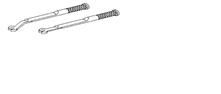
6 Parking brake wire drawing |
|
7.hex flange bolt |
8 Rear frame assembly |
|
:Replace after remove
:N·m![]()
Caution:
● Should thoroughly clean the brake pliers, make damage caused by dust and other substances to a minimum.
● When remove brake pliers, forbid to press brake pedal to avoid the piston ejected.
● To avoid damage piston dust proof when remove.
● Unless dismantle or replace the brake pliers, otherwise prohibited to remove connection bolt of brake pliers and brake hose . After remove the brake pliers, please use the rope hoist brake pliers to avoid pull brake hose.
● If the friction plate and silencing slice are severely corrosion, please replace the new friction plate.
● Avoid brake fluid splash on the brake disc, if yes, please erase immediately.
Remove and install
Friction plate
Remove
1 Remove wheel, please see “Wheel-wheel assembly”
2 Remove rear brake caliper
|
1) Loose parking brake. 2) Remove 2 fixing bolts of rear brake caliper. ● Tightening torque: 22~32N·m 3) Turn up the rear brake caliper assembly. Caution: ● Avoid to pull brake hose. |
|
|
4) Remove friction plate of out and inner brake caliper.
|
|
|
Check after remove Check friction plate thickness with scale. Standard thickness: 14.7 mm Friction limit thickness:7mm
|
|

Caution
● If the thickness of brake shoe is less than wear and tear limit, please replace the friction plate.
Install
Install in the opposite order of remove
Rear brake pliers assembly
Remove
1 Remove wheel, please see “Wheel”
2 Exhaust brake fluid, please see “Maintenance-brake fluid”
3 Remove rear brake plier assembly.
1) Loose parking brake.
|
2) Remove connection of brake hose bolt and copper gaskets with rear brake hose and rear brake caliper. ● Tightening torque: :25~30N·m Caution: ● Please be care the copper gaskets off at both ends of bolt.
|
|
|
3) Remove two bolts of connecting rear brake plier Assembly and rear torque frame assembly ● Tightening torque: 65~75N·m |
|
|
4) Remove the fixing nut and clipper of rear brake plier assembly and rear parking brake wire, take off the connectionof rear brake plier assembly and rear parking brake wire. 5) Take off rear brake plier assembly.
|
|

Install
1`Install rear brake plier assembly
1) Put the rear brake plier assembly on the installation position , pre-tightening fixing bolt of brake plier
|
2) Tightening two bolts of connecting rear brake plier assembly and rear torque frame assembly. ● Tightening torque: 65~75N·m
|
|
|
3) Install connection of brake hose bolt and copper gaskets with rear brake hose and rear brake caliper. ● Tightening torque: 25~30N·m
|
|
4) install the connection of rear brake plier assembly and rear parking brake wire.
2 Fill brake fluid, please see “maintenance-brake fluid”
3 Brake system exhaust, please see “maintenance- brake system exhaust”
4 Install wheel, please see “wheel”
Rear brake disc
Remove
1 Remove wheel, please see “Wheel”
2 Remove rear brake plier assembly, please see rear brake plier assembly.
3 Remove rear brake disc.
|
1) Remove the cross screws of rear brake disc. ● Tightening torque: 10~15N·m 2) Take off rear brake disc. |
|
Check after remove
1 Visual inspection
Check whether the front wheel brake disc surface is uneven wear, crack and serious damage. If yes, please change.
2 Beat quantity check
|
2) Fix front wheel brake disc on wheel hub. Caution: ● Please confirm the wheel axial clearance not too big before measuring.
|
|
3) Check beat quantity with a dial indicator, which could measure on the edge of the brake disc within 10 mm.
● Beat limit quantity:0.05mm
If beat quantity surpass limit, please replace brake disc or do the necessary processing.
3. Thickness check
|
1) Check the thickness of the brake disc with a micrometer. If the thickness is less than wear and tear limit, please replace the brake disc. Standard thickness: 9mm Friction limit thickness:8mm |
|

Install
Install in the opposite order of remove.
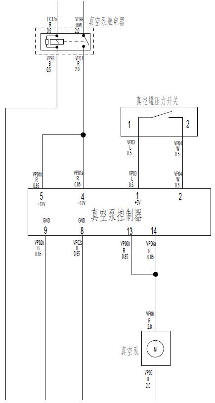
System description
Vacuum booster connect with vacuum tank through the vacuum hose , vacuum pump controller monitor the pressure in the vacuum tank through the pressure switch. When vacuum tank negative pressure is insufficient, the vacuum pump controller control vacuum pump, the suction of the vacuum tank, until the vacuum tank pressure to the limit.
Control logic
1 set up negative pressure: when lack of negative pressure in vacuum tank , the pressure switch on the vacuum tank and output signal to the vacuum pump controller, vacuum pump controller control vacuum pump suction of electricity, vacuum pump start pull out air,increasing the vacuum negative pressure in the tank; When the negative pressure to limit, vacuum pump controller delay about 10 s to break vacuum pump power.
2 Fault diagnosis: when due to unexpected conditions, such as vacuum tank leakage, vacuum pump is damaged, which make vacuum negative pressure can not meet the demand of system, vacuum alarm switch of vacuum tank will output alarm signal to the combination instrument, the braking system fault warning lights on instrument lit.
![]()
![]()
![]()
![]()
![]()
![]()
![]()
![]()
![]()
![]()
![]()
![]()
![]()
![]()
![]()
![]()
![]()
![]()
![]()
![]()
![]()
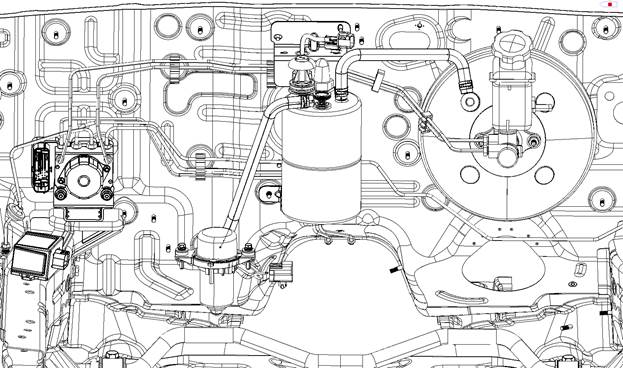
|
1 Vacuum pump controller |
2 vacuum hose I |
3 vacuum tank bracket |
|
4vacuum hose II |
5 vacuum tank |
6 vacuum pump bracket |
|
7 vacuum pump |
|
|
Caution:
● Forbid to distortion, pulling the vacuum hose when remove
● Forbid to damage stud of vacuum tank assembly.
● Forbid to disassemble vacuum pump.
Remove
1 Remove vacuum hose which connect vacuum tank assembly ,vacuum booster assembly and vacuum pump.
2 Unplug the vacuum tank assembly connector, remove the nut connected vacuum tank bracket with the body, remove the vacuum tank assembly and vacuum tank bracket.
● Tightening torque:7~11N•m
3 Remove the connected nut for vacuum tank and vacuum tank bracket.
● Tightening torque:20~25N•m
4 Unplug the vacuum pump connector, remove the vacuum pump and powertrain assembly beam joint bolt, remove the vacuum pump.
● Tightening torque:7~11N•m
5 Unplug the vacuum tank assembly connector, remove the bolt connected vacuum tank bracket with the body, remove vacuum pump controller.
● Tightening torque:7~11N•m
Check after remove
1 Vacuum pump controller
Check the connectors for cracking, curved needle or other damage. If yes, please replace.
2 Vacuum hose
Check whether there are cracks and aging or other damage. If yes, please replace.
Tips:
● vacuum hose has a multilayer structure to ensure the tightness and durability, minor cracks on surface will not affect the usage.
3 Vacuum tank assembly
Check whether there is a tank corrosion, aging and cracking of rubber parts, or other damage. If yes, please replace.
Install
Install in the opposite order of remove
Caution:
● Install the vacuum hose, banning the use of lubricating oil.
Maintenance data and specification
Specification
|
Item |
Specification |
Item |
Specification |
||
|
Brake bump
|
Type |
In series |
Parking brake |
Type |
Rear wheel mechanical brake |
|
Cylinder diameter |
22.22mm |
Brake typ |
Lever |
||
|
Brake booster |
Type |
Vacuum booster |
Zip arrangement |
V type layout |
|
|
Effective diameter |
255mm |
Wheel speed sensor |
Type式 |
Magneto-electric |
|
|
Booster proportion |
7.3:1 |
Resistance |
1-2KΩ |
||
|
Front brake |
Type |
Floating type/with ventilation |
Output voltage |
Alternating |
|
|
Brake disc diameter |
294mm |
Air clearance |
0.2-1.1mm |
||
|
Brake disc thickness |
25mm |
ABS, EBD warning light |
type |
Warning light module |
|
|
Friction plate thichness |
9.5mm |
Working voltage |
12V |
||
|
Cylinder diameter |
54mm |
Working current |
80mA |
||
|
Rear brake |
Type |
Floating type/ solid plate |
Vacuum tank |
volume |
2L |
|
Brake disc diameter |
275mm |
Voltage switch set point |
-50±5 kPa |
||
|
Brake disc thickness |
9mm |
Voltage switch set point |
-50±5 kPa |
||
|
Friction plate thichness |
14.7mm |
Sealing Sealing |
-66.7±3kPa 15s,15s inner voltage decrease |
||
|
Cylinder diameter |
54mm |
||||
|
Vacuum pump |
Rated voltage |
12V |
|||
|
Working voltage |
10-16V |
||||
|
Working temperature |
-40 -120℃ |
||||
|
Working current |
<17A |
Protection grade |
IP65 |
||
|
Start current |
≤90A(100ms) |
||||
|
Working time of vacuum pump(one time, 4L volume) |
1000mbarto 500mbar:≤3.5s 1000mbar to 300mbar:≤7s |
||||
|
Noise |
≤77dB |
||||
|
Protection grade |
IP55 |
||||
|
Item |
Standard value |
Item |
Standard value |
Limitation |
|
Height of brake pedal |
271mm |
The thickness of the front brake shoe |
9.5mm |
7.5mm |
|
Brake pedal stroke |
127.5mm |
Front disc thickness |
25mm |
23mm |
|
Space between brake lamp switch outside and the pedal stock |
0.5~1.0mm |
Front /rear disc jump |
0.025 |
0.05mm |
|
Brake pedal free stroke |
3~8mm |
Thickness of rear disc brake friction plate |
14.7mm |
7.7mm |
|
Booster air travel |
0~0.5mm |
Thickness of rear disc |
9mm |
7mm |
|
The length of booster push rod B |
117mm |
Parking brake lever stroke (when add 196 N force to block assembly) |
5-7 tooth |
|