Cautions for electrical technicians using medical electrics
Forbidden operation
Warning:
● There is strong magnetic components on this vehicle
● If technician use medical electrics, e.g. electronic pacemakers, which couldn’t be operated in the vehicle ,otherwise, the function of electrics may be effected by strong magnetic components.
Cautions for normal charge
Warning:
● If technician use the medical electrics like pacemakers, cardiovascular, in addition to the top, the machine only could be used after the function of machine checked and confirmed before normally operation.
● In the normal charging operation, Medical electrics may be affected by electromagnetic wave. When Technicians use the medical electrics like pacemakers, cardiovascular, in addition to the top etc, it is not allowed to enter into crew capsule (including luggage).
Cautions for communication equipment
Warning:
● If technicians use the medical electrics like pacemakers, cardiovascular, please keep distance more than 220mm between the key parts and the inner and outer antenna.
● The electromagnetic wave of transmission control unit may affect the function of pacemakers or cardioverter .
● Before the use of medical devices such as pacemakers or cardioverter, the electromagnetic waves of transmission control unit may affect the function of the equipment, the function of the medical equipment must be checked and confirmed no problem before using.
Cautions for operation of smart start system
Warning:
● If technicians use the medical electrics like pacemakers, cardiovascular, please keep distance more than 220mm between the key parts and the inner and outer antenna.
● The electromagnetic wave of smart start system may affect the function of pacemakers or cardioverter such as control the door、close and open of the switch and engine start.
● Before the use of medical devices such as pacemakers or cardioverter, the electromagnetic waves of smart start system may affect the function of the equipment, the function of the medical equipment must be checked and confirmed no problem before using.
Checking points before maintenance
Check high voltage system to confirm that the high voltage is off and battery maintenance switched off before maintenance.
Cautions for "safety airbag"and"safety belt preloaded"of auxiliary constraint system
The combination use of "safety airbag"and"safety belt preloaded"of auxiliary constraint system and front seat belt could decrease the damage to driver and passengers when collision. This system includes safety belt switch input and double front airbag muddle. SRS system use safety belt switch to confirm the opening of front airbag, maybe only open one airbag which depends on the damage degree and whether the front passenger is with seat belt.
The detailed information could refers to the sections of “SRS” and “safety belt” in the maintenance manual.
Warning:
To avoid unexpected accident, we need to obey the following:
● To avoid the SRS invalid, all the maintenance only could be operated by JAC/IEV5 authorized distributors because the risk of injury to people caused by airbag collison will be increased after invalid.
● Improper maintenance, including wrongly removal and installation of SRS system will make the system has no intention of activation leading to injuries. For spiral cable and airbag module, see "SRS AIR BAG".
● Unless commissioned in the maintenance manuals, don't use electronic in the circuit associated with SRS test equipment. SRS wiring harness with yellow and/or orange wire or wiring harness plug can easily be recognized.
Cautions when use electrical tools (pneumatic or electric)and hammer
Warning:
To avoid unexpected accident, we need to obey the following:
● When the power switch is on, approaching the airbag diagnosis sensor or other airbag system sensor, please do not use pneumatic or electric tools or hammer to hammer on the sensor attachment area. Severe vibration may activate the sensor, and open the airbag, which can result in serious injury.
● When using pneumatic or electric tool or a hammer, switch off the power supply, unplug the 12 v lead-acid storage battery pile head, waiting for at least 3 minutes and then do the maintenance.
Cautions for removing 12V battery
● Before moving the 12 v battery, open or shut off the power switch to check whether the charging status indicator is flashing. After inspection within one hour after the indicator light must take away the 12 v battery.
Tips:
● When the power switch is OFF, battery charging control system may start automatically.
● When the power switch ON/OFF, automatic battery charging control system will not start within an hour.
Cautions for maintenance to the driving shaft
● It is not allowed to remove the non-overhaul components such as steering knuckle
● Try best to operate on the workbench without dust.
● Please clean the parts surface before remove and assembly.
● Please care to avoid make parts dirty and prevent foreign things in.
● The disassembled parts must be reassembled carefully and in accurate order. If the work is terminated, please cover the parts with clean cover.
● Must use paper cloth to prevent the chip attached on the parts when using the fiber weaving cloth.
● Dismantled parts (except for rubber parts) should use kerosene to clean and dry or dry with paper cloth
Cautions for checking 、maintenance or parts changing
● Must check the specified torque of fixed parts after assembly.
● Must do the necessity positioning check after assembly.
● The disposable parts can't reuse
● Please check thoroughly before remand or change parts.
Special tools
Actual tool shape may be different from illustration shown as following
|
Tool |
Diagram |
Instruction |
|
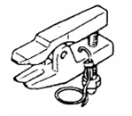
Steering transmission rod |
|
Remove the connecting ball head |
|
Tool |
Diagram |
Instruction |
|
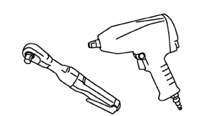
Power tool |
|
Install and remove bolts and nuts |
Troubleshooting for noise,vibration and unsmooth(NVH)
NVH troubleshooting diagram
Using the table below helps to find the causes of symptoms. If necessary, repair or replace these parts.
|
reference |
-- |
-- |
-- |
Front axle-7 |
-- |
Front axle-10 |
Front axle and front suspension |
Front axle |
NVH of wheel |
NVH of whee |
Driving shaft |
NVH of braking part |
NVH of steering part |
||
|
Possible reason and parts |
Universal joint angle is too big |
Sliding resistance of universal joint |
unbalance |
Unfitable insatllation ,ls |
Parts interference |
Wheel bearing damaged |
Front axle and front suspension |
Front axle |
tyre |
Wheel |
Driving shaft |
Brake |
Steering |
||
|
symptom |
Driving shaft |
Noise |
× |
× |
|
|
|
× |
× |
× |
× |
× |
|
× |
× |
|
Vibration |
× |
|
× |
|
|
× |
× |
× |
× |
× |
|
× |
× |
||
|
Front axle |
Noise |
|
|
|
× |
× |
× |
× |
|
× |
× |
× |
× |
× |
|
|
Vibration |
|
|
|
× |
× |
× |
× |
|
× |
× |
× |
× |
× |
||
|
Shaking |
|
|
|
× |
× |
× |
× |
|
× |
|
× |
|
× |
||
|
fibrillation
|
|
|
|
× |
× |
|
× |
|
× |
× |
|
× |
× |
||
|
Uncomfortable or difficult to operate |
|
|
|
× |
× |
|
× |
|
× |
× |
|
|
|
||
×:Fittable
Check and Maintenance
1 Check whether the driving shaft and universal joint is loose and other damages.
2 Check whether anti-dust cover has cracks and other damage
Caution:
● If the driving shaft appears noise or vibration, please replace the driving shaft assembly.
Anti-dust cover of driving shaft replacement
1 Lift vehicle, remove front tire. Please refer to “wheel and tire”
● Tightening torque: 90~110 N·m
2 Remove the wheel speed sensor from universaljoint. Please refer to “wheel speed sensor”.
Caution:
● Please don’t pull the wheel speed sensor harness.
● Tightening torque: 8~10 N·m
3. Remove the front brake caliper assembly from the steering knuckle, and hung fixed. Please refer to the “front brake pliers”.
Caution:
● Ban to press on the brake pedal after removing the brake caliper assembly.
● Tightening torque: 65~75N•m
4 Loose the locking nut of driving shaft
● Tightening torque: 240~260N•m
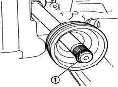
5 Tapping the driving shaft with a hammer (or the right tool) and wood make it separate with rim and bearing assembly, then remove the locking nut of driving shaft.
Caution:
● The angle for universal joint placed at shaft fixing end shall not be too big and do not pull and move it.
● Be sure to support universal joint spherical shell 、shaft and other parts when put down the driving shaft.
● If couldn’t separate rim and driving shaft as above operation, you could use pulling tools (or appropriate tools).
|
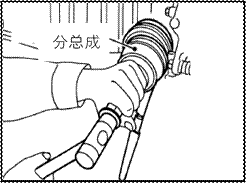
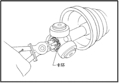
6 Remove steering rod ball head from the steering rod. |
|
|
Caution: ● Use special tool to avoid to damage ball head dust-proof ● Tightening torque: 15~34N•m |

7 Loosen the fixing bolts and nuts of absorber and steering joint.
● Tightening torque: 75~90N•m
8 Separate driving shaft from rim and bearing
Caution:
● The angle for universal joint placed at shaft fixing end shall not be too big to avoid pushing and the ball cage off.
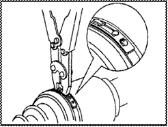
9 Remove the dustproof sleeve clamp
|
10 Screw driving shaft puller (or the appropriate tools) into the bolt hole of universal joint subassembly; pull the universal joint shaft assembly from holes. |
|
|
Caution: ● If couldn’t pull out universal joint subassembly,please try again after removing the driving shaft from the vehicle |
|
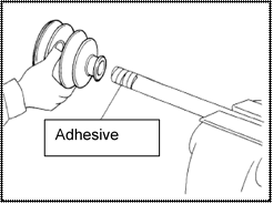
|
11 Remove the ring clamp from the driving shaft, and remove the dust-off cover. 12 Dry the grease with paper on the joint universal assembly. |
|
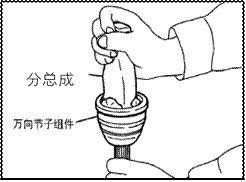

|
13 Apply the right amount of grease in the dentate hole of the universal joint subassembly,Until grease liquid from the circular groove and dentate hole. Dry the old grease with after daub lubrication fat. 14 Wrap spline with tape to avoid damage dustproof. Install the new dust Set and dustproof sleeve clamp on the driving shaft. |
|
Grease type: CVJM-2008J
Filling Qty: 120g±10g
Caution:![]()
● please don’t repeatedly use dustproof and dustproof sleeve clamp.
15 remove the tape on the bearing.
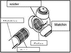
16 Place the snap ring on the groove of the shaft edge. Align the bearing on the edge of the shaft with universal joint subassembly alignment. Then install the bearing on the universal joint subassembly with snap ring.
Caution:
● Please don’t repeatedly use the snap ring
● when installing snap ring, please use special tool
17 Install the universal joint subassembly on the drive shaft with a plastic hammer.
Caution:
● Confirm universal joint subassembly has
Meshing correctly when rotating drive shaft.
|
18 Daub evenly the right amount of grease to the inside of dust proof from large diameter side of dust proof. 19 Install dust proof into the shell ridge as shown in the picture |
|
Caution:
● If grease stick to dust proof fixed on the surface (pictured as *), to prevent dust proof from falling off, please wipe clean.
|
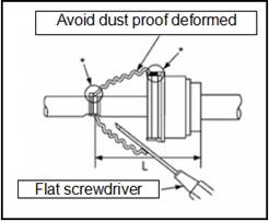
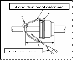
20 Inserted flat screw driver from large diameter side of dust proof, let the air outside, and adjust the dust proof installation length, avoiding dust proof deformation. Caution: ● If dust proof drawing is prolonged, it may be damaged. ● Be careful with flat screwdriver, avoid to damage dust proof. |
|
21 Fixed the new dust proof with tools
Caution:
● Forbidden to reuse dust proof clamp.
22 Fix the universal joint and driving shaft to confirm the dust cap installed in the correct position.
Caution:
● Dust proof installed in wrong position, please use the new dust proof clamp to install.
23 Confirm cir-clip meshing completely at the moving end of driving shaft.
24 Insert the driving shaft into front wheel assembly, then tighten the locking nut of the driving shaft.
25 Install bolts and nuts of absorber and steering joint.
26 Install steering rod ball and fix the nut with standard torque.
Caution:
● when install, fix bolt first to avoid rotating then locking nut.
27 Install brake pliers components, fixing brake hose.please refer to “front brake”and “brake pipe”.
28 Install steering joint on the wheel speed sensor. Please refer to “wheel speed sensor”.
29 Tighten the the locking nut of driving shaft to standard torque.
● Tighten torque: 240~260N·m
30 Install tyre and tighten with standard torque. Please refer to “maintenance specification”
Explosion diagram

|
1 Hub assembly |
2 left front driving shaft assembly |
|
3 Reducer assembly |
4 Right front driving shaft assembly |
Remove
1 Lift the vehicle and remove the front tyre. Please see the "wheel and tyre”.
2 Remove the wheel speed sensor from the steering joint. Please see the " wheel speed sensor".
Caution:
● Pull wheel speed sensor wiring harness is prohibited.
3 Remove the braking clipper assembly from steering joint and fix it. Please refer to front braking clipper”.
Caution
● Don’t press down the braking pedal after removing braking clipper.
4 Remove brake disc
5 Loosen driving shaft locking nut.
6 Separate fixed end of driving shaft and the front wheel assembly with a hammer (or the right tool) and wood tapping the driving shaft.
Caution:
● The angle for universal joint placed at shaft fixing end shall not be too big and please also be care do not push the moving joint too much.
● Please assure to support the Shell (components) of universal joint, shaft and other parts when put down the driving shaft.
● If still couldn’t separate the rim and driving shaft, please use the puller(or other tools)
7 Remove the tie rod from the steering knuckle ball head.
Caution:
● To avoid damage the dust-proof of ball head, please use special tools.
8 Loosen fixed bolts and nuts of shock absorber and steering knuckle.
9 Remove the driving shaft from the hub and bearing assembly .
10 Pry out of the driving shaft from the reducer side.
Caution:
● The angle for universal joint placed at shaft fixing end shall not be too big and please also be care do not push the moving joint too much.
Check after remove
1 Turn the universal joint to check whether it is flexible, smooth, or any serious loose.
2 Check whether there is crack, breakage and dust proof grease leakage.
3 If there happens the conditions not in line with the specification, please disassemble the driving shaft and replace defective parts.
Installation
Install in the opposite order of remove. About the tightening torque, please refer to “Maintenance specification”
Caution:
● Before installing the driving shaft, a new reducer oil seal should be replaced.
● Forbidden to reuse the components which couldn’t be reused.
● Insert the driving shaft reducer side,avoiding to damage the oil seal
● confirm the cir-clip meshing completely.
● Applying gear oil on the spline of driving shaft.
● When installing the driving shaft, make the cir-clip opening facing down.
Explosion

![]()
![]()
![]()
![]()
![]()
![]()
![]()
![]()
![]()
![]()
![]()
![]()
![]()
![]()
|
1 Cir-clip |
2 shell |
3 snap ring |
4 Trigeminal assembly |
5 dust proof |
|
6 clamp of dust proof |
7 locking nut |
8gasket |
9 dust cover |
10 wheel speed sensor gear ring |
![]() Replace
after remov
Replace
after remov
Disassemble
On the side of reducer
|
1 Fixing driving shaft in vise. Caution: ● When fixing driving shaft in vise, please use aluminum or copper plate to protect the driving shaft. |
|
|
|
|
|
|
2 Remove the dustproof sleeve clamp, and then remove the dustproof from shell in the set.
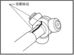
3 Mark on the spherical shell and driving shaft , pull the ball shell.
Caution:
● Marking with painting or similar materials.
Please don't scratch the surface.
|
4 Remove the snap ring and fork assembly. |
|
|
5 Remove the dust proof from driving shaft |
|
|
6 Use paper cloth dry the old grease on the removed parts. |
On the side of wheel
1 Fixing the driving shaft in vise
Caution:
● When fixing driving shaft in vise, please use aluminum or copper plate to protect the driving shaft.
2 Remove clamp of dust proof
3 Make driving shaft puller (or appropriate tools) totally screwed into the universal joint thread, then separate the driving shaft from the universal joint.
Caution:
● If try many times still not successfully remove the universal joint, please replace the drive shaft assembly.
4 Remove the cir-clip from driving shaft, take out the dust proof
5 Remove the gear ring of wheel speed sensors from the driving shaft.
6 Turning the ball shell and use paper cloth wipe grease on the removed parts.
Check after removing
Driving shaft
Check whether there is any deformation , crack, rust or other damage on the driving shaft rod. If yes, please replace driving shaft assembly.
Subassembly of universal joint (wheel side)
Check:
● Check whether the gimbal subassembly is excessive spin and the driving shaft is too loose.
● Whether there is a foreign body in the inside of universal joint.
● Check whether there is universal joint compression deformation, cracks and internal damage.
If found that do not conform to the provisions of the state, please replace the universal joint subassembly.
Shell and fork assembly(in the side of reducer
Check whether there are scratches or wear and tear in the rolling contact surface between ball shell and trigeminal assembly, if yes, please replace at the same time.
Caution:
● Shell and fork assembly in a device.
Dust proof and wheel speed sensors
● Check whether there are cracks or other visible damage. If yes, please replace.
Install
In the side of reducer
1 Wrapped spline with tape to avoid damage dust proof, install the new dust proof on the driving shaft and fastening clamp at small end
|
Caution: ● Forbidden to repeat use damaged dust proof and clamp. 2 Demolish adhesive tape around the driving shaft spline. |
|
|
3 When assembly fork assembly,line in the paint marker, install fork assembly with reverse angle to bearing. |
|
|
4 Fix fork assembly to the shell with snap ring. 5 Use the recommended lubricating oil daub trigeminal assembly and slippery surface. 6 Install the shell to the trigeminal assembly, then apply recommended grease. |
|
|
7 Install the clamp into the slot as show in the picture Caution: ● If grease stick to dust proof fixed on the surface , dust proof may fall off, please wipe clean. 8 Inserted flat screwdriver from large diameter side of dust proof, let the air outside, and adjust the dust proof installation length, avoiding dust proof deformation. |
|

Caution:
● If dust proof drawing is prolonged, it may be damaged.
● Be careful with flat screwdriver, avoid to damage dust proof.
9 Fix new dust proof clamp with special tools
Caution:
● Forbidden to reuse dust proof clamp.
10 Fix shell and driving shaft ,then confirm the dust cap installed in the correct position.
Caution:
● Dust proof installed in wrong position, please use the new dust proof clamp to install.
11 install wheel speed sensor and sustproof to the shell.
In the side of wheel
Assemble in accordance with step 14~ 23 of "replacement of driving shaft dust proof”
Caution:
● When assembling, should guarantee the universal joint assembly in line with driving shaft.
● When assembling, confirm the wheel speed sensor and shell is matched completely.
● Please install wheel speed sensor after pressing into dustproof.
Maintenance data and specification
Wheel bearing
|
Item |
Standard value |
|
Clearance between bearing end |
0.05mm or less |
Driving shaft
|
|
Wheel side |
Reducer side |
|
Universal joint type |
AC |
GI |
|
Grease volume |
120g±10g |
120g±10g |