Cautions for electrical technicians using medical electrics
Warning:
● There is strong magnetic components on this vehicle
● If technician use medical electrics,e.g electronic pacemakers, which couldn’t be operated in the vehicle ,otherwise,the function of electrics may be effected by strong magnetic components.
Cautions for normal charge
Warning:
● If technician use the medical electrics like pacemakers, cardiovascular, in addition to the top, the machine only could be used after the function of machine checked and confirmed before normally operation.
● In the normal charging operation, Medical electrics may be affected by electromagnetic wave. When Technicians use the medical electrics like pacemakers, cardiovascular, in addition to the top etc, it is not allowed to enter into crew capsule (including luggage).
Cautions for communication equipment
● If technicians use the medical electrics like pacemakers, cardiovascular, in addition to the top etc, please keep enough distance with the communication equipment.
● Remote intelligent terminal of electromagnetic waves may affect the function of the medical electrics like pacemakers, cardiovascular, in addition to the top etc.
● If technicians use the medical electrics like pacemakers, cardiovascular, in addition to the top etc, remote intelligent terminal of electromagnetic waves may affect the function of the medical electrics. It is needed to let the manufacturer of the medial electrics confirm that the possible affection to medical electric equipment when using remote intelligent terminal .
Keypoint checking before maintenance
High pressure system can be run automatically, it is need to confirm that remote air conditioning and recharged regularly are not set before maintenance.
Cautions:
● If set remote air-conditioner or charged regularly, even though the switch is closed, high pressure system can be run automatically.
Cautions for "safety airbag"and"safety belt preloaded"of auxiliary constraint system
The combination use of "safety airbag"and"safety belt preloaded"of auxiliary constraint system and front seat belt could decrease the damage to driver and passengers when collision. The auxiliary constraint system include seat belt, airbag for driver, airbag for co-driver. The detailed information for auxiliary constraint system could refers to the sections of “airbag system” and “seat belt”
Warning:
To avoid unexpected accident, we need to obey the following:
● To avoid the auxiliary constraint system invalid, all the maintenance only could be operated by JAC authorized distributors because the risk of injury to people will be increased after invalid.
● Non-standard auxiliary constraint system of maintenance including non-standard disassembly and installation, may result in auxiliary constraint system accident triggered, causing personal injury accidents. About remove the airbag module method, please see "airbag system" section.
● In addition to the maintenance instructions in the manual operation, do not use electrical test equipment to test any circuit of auxiliary constraint system. Auxiliary constraint system of connectors and wiring harness use yellow or orange color.
Cautions when use electrical tools (pneumatic or electric)and hammer
● when electric switch in the "ON" block, near the airbag diagnostic sensors or other sensor, do not use power tools or hammer to operate sensor parts area. Severe vibration may activate the sensor, some airbags, causing serious damage.
● When using power tools or hammer, put the keys in the "LOCK" block, unplug the 12 v lead-acid battery cathode, waiting at least 1 minute, then for checking and maintenance.
Cautions for removing 12V battery
Turn the key to “on”,then to “lock” before remove 12v battery
Tip:
● Even if the key in the "LOCK" and the 12 v battery charging function may start automatically.
● After turn the key to "ON" --> "LOCK", 12 v battery automatic charging will not start.
Cautions for front suspension maintenance
● When installing the rubber bushing, Bolts shall be screwed under the condition of unloading and tire hit the road.
● Not repeatedly use the locking nut.
● There shall not be oil and grease in the installing tightening surface .
● Check wheel positioning after suspension parts maintenance.
The factual tool shape may be different with the diagram showing.
|
Tool |
Diagram |
Instruction |
|
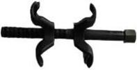
Steering transmission rod die |
|
Remove the connecting ball head |
|
Helical spring puller |
|
Disassembly and installation of helical spring |

|
Tool |
Diagram |
Instruction |
|
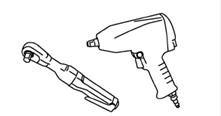
Power tool |
|
Install and remove bolts and nuts |
Troubleshooting for noise,vibration and unsmooth(NVH)
Using the table below helps to find the causes of symptoms. If necessary, repair or replace these parts.
|
Referring content |
Front suspension-remove and install |
Front suspension-shocker absober check |
-- |
-- |
-- |
Front suspension-remove and install |
Front suspension-wheel positioning |
Front suspension-Stabilizer bar |
Front axle and front suspension NVH |
Wheel NVH |
Wheel NVH |
Front axle NVH |
Braking system NVH |
Steering system NVH |
|||
|
Possible reason and parts |
Improper install, loose |
shock absorber deformed, damaged or bending |
Bushing aging |
Parts interference |
Spring fatigue |
Suspension loosing |
Not accurate for wheel positioning |
Stabilizer bar fatigue |
Front axle and front suspension |
tyre |
wheel |
Driving shaft |
Brake |
Steering system |
|
||
|
symptom |
Front suspention |
Noise |
√ |
√ |
√ |
√ |
√ |
√ |
|
|
√ |
√ |
√ |
√ |
√ |
√ |
|
|
Vibration |
√ |
√ |
√ |
√ |
|
√ |
|
|
√ |
√ |
√ |
√ |
√ |
√ |
|||
|
Shaking |
√ |
√ |
√ |
√ |
√ |
|
|
|
√ |
√ |
|
√ |
|
√ |
|||
|
fibrillation |
√ |
√ |
√ |
√ |
|
|
√ |
|
√ |
√ |
√ |
|
√ |
√ |
|||
|
Uncomfortable or difficult to operate |
√ |
√ |
√ |
√ |
√ |
|
√ |
√ |
√ |
√ |
√ |
|
|
|
|||
√:fitable
Caution:
● Check wheel positioning under unloading position.
● Just adjust front beam, camber angle, kingpin caster angle and kingpin inclination angle couldn’t be adjusted.
● If the camber angle, kingpin caster angle and kingpin inclination is not in the scope of the standard, please check whether there is worn or damaged in the front suspension, front wheel hub assembly, post assembly and ball pin of hem arm assembly. If yes, please replace.
● Check whether tire pressure is normal, whether the tire has abnormal wear. Please see the "wheel - wheel assembly.
● The front wheel hub assembly axial clearance. Please see the "front axle - front wheel hub assembly.
● Check the ball pin axial clearance of hem arm assembly. Please see the "front suspension - the hem arm assembly.
● whether each tightening parts of front axle and suspension is loosing
● Whether there are cracks, deformation or other damage in the parts of wheel hub assembly, front mast assembly and hem arm assembly .
If you find the above situation, please check after maintenance wheel alignment.
Caution:
● Check wheel positioning when vehicle unloading and on the leveling position. If front mast is not in the standard range,Please adjust according to the following step.
|
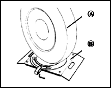
1 place the vehicle on four-wheel locator(B),front wheel (A) is placed on the steering plate. 2 Set standard front mast value on four- wheel locator 3 straighten the steering wheel and fixed. |
|
|
4 loose locking nut (D) of left and right tie rod (C) end. 5 Turning left and right interior rod(E) In clockwise or counterclockwise to adjust front mast data to standard value |
|
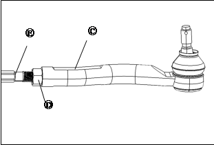
Caution:
● steering amount of left and right interior tie rod shall be the same.
6 Lock the locking nut at the tie rod end.

|
1 Front mast assembly |
2 Front vice frame |
3 Front rim assembly |
4 Hem arm assembly |
1 Remove front wheel, please see “wheel-wheel assembly”.
2 Remove wheel speed sensor, please see “ braking control system-wheel speed sensor”
Caution:
● Pull wheel speed sensor wiring harness is prohibited.
3 Remove the brake hose fixed bolt and remove brake hose. Please see the "brake system - brake pipe".
|
4 Remove the fixed bolts and nuts of front mast assembly and steering knuckle. |
|
|
● Tightening torque:110~120N·m |
|
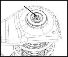
|
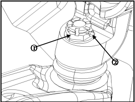
5 Remove the nut dustproof of front mast assembly |
|
|
6 Remove the fixed nut of front mast assembly and body. ● Tightening torque:60~72N·m 7 Take off front mast assembly. |
|

Install in the opposite order of remove
● Forbidden to repeated to use the installing nut of front mast assembly.
● Tightening parts shall be tightened under unloading condition.
● Check wheel positioning . Please see “front suspension-wheel positioning”
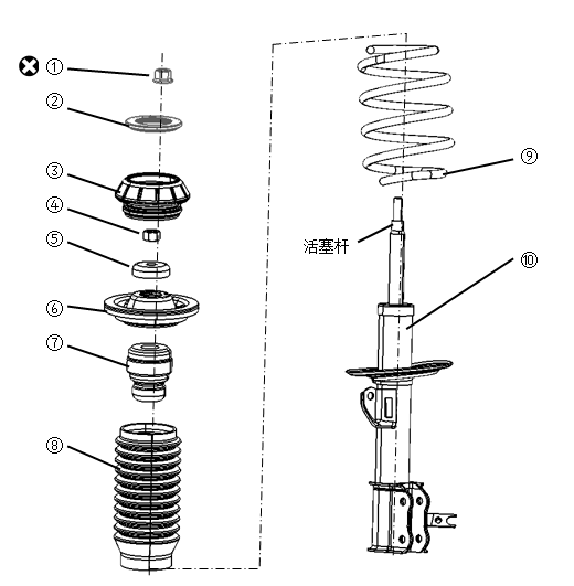
|
1 Nut |
2 Decorative cover |
3 upper supporting assembly |
4 Nut |
|
5 Shock absorber bearing |
6 upper trampoline |
7 Cushion block |
8 Dust proof |
|
9 Helical spring |
10 Front shock absorber |
|
|
![]() :Replace
after disassembly
:Replace
after disassembly
Caution:
● Forbid to damage the front shock absorber piston rod
|
1 Use spring puller to compress spiral spring, until it separated with trampoline. |
|
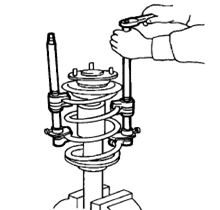
Caution:
● Confirm the puller has been completely installed, and then began to compress.
● Banning to use pneumatic tools to tighten the screw spring puller.
2 Fixing shock absorber piston rod end, remove the locking nut of the piston rod.
3 Remove the shock absorber bearing, spring cushion, dust proof, cushion block.
4 Remove the helical spring with puller, then slowly loosen the puller, remove the coil spring.
Check after disassembly
Front shock absorber
● Check whether there is deformation, crack, leakage, or other damage. If yes, please replace.
● Check whether the piston rod is damaged, wear or deformation. If yes, please replace.
Upper spring cushion, cushion block and dust proof
Check whether there is a crack, the rubber parts for wear, aging or other damage. If yes, please replace.
Helical spring
Check whether there is deformation, crack, rust, wear and tear or other damage of spiral spring. If yes, please replace.
Shock absorber bearing
Check for wear, noise, or other damage. If yes, please replace.
Install in the opposite order of disassembly.
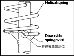
Caution:
|
● Forbid to damage the front shock absorber piston rod ● let large diameter end of helical spring to downwards, aiming at the downside spring seat. ● Confirm the puller has been completely installed, and then began to compress. ● When disengage the puller, should check whether the coil spring installation location is correct. |
Put
spring in right place, |
1 Remove tightening parts of the steering gear assembly,intermediate axle and steering knuckle.Please see “ steering system-steering assembly”
2 Remove the downside protection board of front-tank
3 Remove the connected nut of stabilizer bar pull rod and former post assembly.
4 Remove the fasteners of left and right lower swing arm assembly and the steering knuckle.
Please see “front suspension-lower swing arm assembly”.
5 Remove rear suspension soft mat and bracket. Please see the "suspension system - rear suspension soft mat and bracket.
6 Remove the connecting nut between power battery under guard Ⅰ and vice frame.
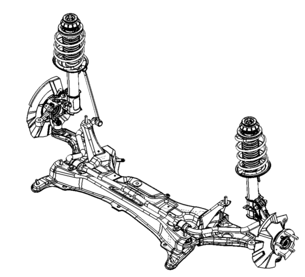
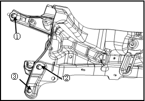
7 Remove the fixing bolt of auxiliary frame and body , remove the auxiliary frame and redirector assembly and left and right hem arm assembly fixed on the auxiliary frame.
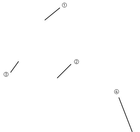
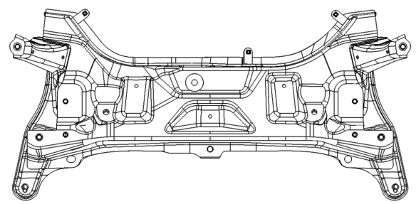
|
● Tightening torque(①):130~150N·m ● Tightening torque(②):130~150N·m ● Tightening torque(③):60~72N·m |
|
8 Remove the steering gear assembly on the auxiliary frame .Please see the "steering system -steering assembly".
9 Remove the stabilizer bar and stabilizer bar on the pull rod of auxiliary frame. Please see the "front suspension -stabilizer bar".
10 Remove left and right lower swing arm assembly. Please see the "front suspension - the lower hem arm assembly.
Check after remove
Check whether there is a crack, rust or other visible damage. If yes, please replace.
Install in the opposite order of remove.
Installation bolt screwing order of vice frame :②→①→③
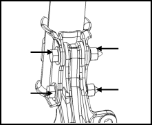
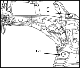
|
1 Lifting the vehicle, remove the front wheels. Please see "wheel - wheel assembly. 2 Remove the cotter pin (①)on ball pin of hem arm assembly. 3 Remove the slot type nut (②)connecting ball pin of hem arm assembly with steering knuckle. ● Tightening torque:60~72N•m |
|
|
4 Remove fixing bolt(①)for front installing bushing of hem arm assembly and the auxiliary frame . ● Tightening torque:130~150N·m 5 Remove fixing bolt(②)for rear installing bushing of hem arm assembly and the auxiliary frame. ● Tightening torque:130~150N·m |
|
6 Use hammer (or the right tool) and wood tapping hem arm assembly slightly, separate hem arm assembly and steering knuckle, remove the hem arm assembly.
Check after remove
Visual check
● Check whether the bushing is worn or damaged. If yes, please replace.
● Check whether the hem arm assembly has deformation or other damage. If yes, please replace.
● Check if there is a crack, damage, aging or other damage in the ball pin dust proof of hem arm assembly. If yes, please replace.
Swing torque check for the ball pin
1 Turn the ball pin stud at least 10 times, check whether there is the binding. If yes, please replace the hem arm assembly.
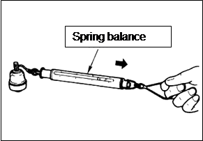
2 Lift a spring balance in the ball pin stud slit . Measuring pin ball stud started turning force, calculating oscillating torque.
|
oscillating torque:1~3N·m Spring balance showing range:16.7~50N If surpass the specified range, please replace hem arm assembly. |
|
The ball pin axial clearance check
Move the ball pin stud along the axial , measuring axial clearance.
axial clearance:≤0.2mm(adding±850N force along axial)
If surpass the specified range, please replace hem arm assembly.
Install in the opposite order of remove
Caution:
● Forbid to use the damaged parts.
● Tightening tighten parts when vehicle unloading.
● Check wheel positioning, please see “front suspension-wheel positioning”
|
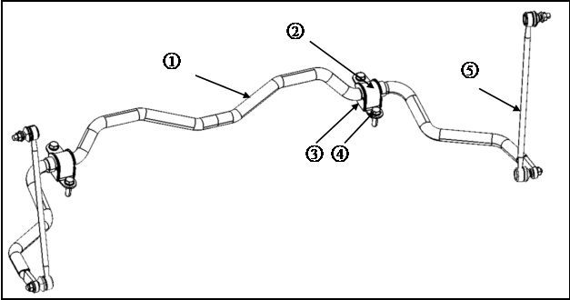
1 Stabilizer bar |
2 Fixing bracket of stabilizer bar |
3 Bushing of stabilizer bar |
|
4.Bolt |
5 Rod of stabilizer bar |
|
|
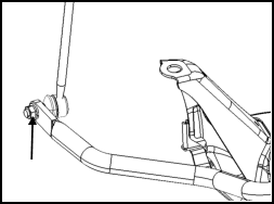
1 Remove the front auxiliary frame and redirector assembly fixed on the auxiliary frame, left and right hem arm assembly parts. Please see the "front suspension - front auxiliary frame". 2 Remove the steering gear assembly on auxiliary frame. Please see the " steering system -steering assembly". 3 Remove the fixing nut of stabilizer bar rod and stablizer Rod,remove the stabilizer bar rod. ● Tightening torque: 55N·m~65N·m |
|
|
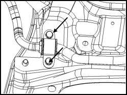
4 Remove the bolts for stabilizer bar fixing Bracket and take off stabilizer bar and bushing. ● Tightening torque: 60N·m~72N·m |
|
Check after remove
Check whether there is deformation,wearing or other damages in stabilizer bar,stabilizer bar rod and stabilizer bar fixing bracket, if yes, please replace.
Check whether there is crack, aging, wear and tear or other damage on stabilizer bar bushing, stabilizer bar rod liner . If yes, please replace.
Install in the opposite order of remove
Caution:
● Forbid to use unrepeatable used parts.
● Diagonal tighten stabilizer bar fixing bracket bolts.
1 Remove front wheel, please see “wheel-wheel assembly”.
2 Remove wheel speed sensor, please see “ braking control system-wheel speed sensor”
Caution:
● Pull wheel speed sensor wiring harness is prohibited.
3 Remove the brake hose fixed bolt and remove brake hose. Please see the "brake system - brake pipe".
4 Remove the brake caliper assembly and suspension fixed. Please see the "brake system - brake pliers.
Caution:
● Forbidden to pedal on the brake pedal after removing the brake caliper assembly .
|
5 Remove the limit screw of brake disc , remove the brake disc. 6 Remove the retaining bolt of front pillar assembly and front wheel assembly. ● Tightening torque: 100N·m~120N·m |
|
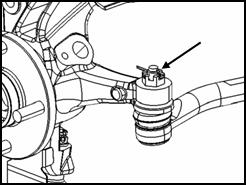
7 Remove the locking nut of drive shaft
● Tightening torque: 240N·m~260N·m
8 Tapping the drive shaft with a hammer (or the right tool) and wood to separate from front wheel assembly.
Caution:
● Please use puller (or fittable tool) if couldn’t seperate according to above procedure.
● After the separation, must support fixed end gimbal spherical shell and the shaft.
● Angle of universal joint drive shaft at fixed end shall not too big, and do not pull move section.
|
9 Remove ball head of steering pulling bar .please see “steering system- mechanical steering of steering assembly Caution: ● Please use special tool or proper tool to avoid Damaging dust-proof of ball head |
|
10 Remove the ball pin of downside hem arm. Please see the "front suspension - the downside hem arm assembly.
Caution:
● Please use special tool to avoid to damage the dust proof of ball pin.
11 Remove front hub assembly
Check after removing
● Check if parts deformation, cracks or other damage. If yes, please change.
Install in the opposite order of remove
● Forbidden to repeated to use the installing nut of front mast assembly.
● Tightening parts shall be tightened under unloading condition.
● Check wheel positioning . Please see “front suspension-wheel positioning”
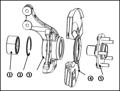
|
1 Bearing |
2 Circlip |
3 Front steering knuckle |
|
4 Fender |
5 flange |
|
1 Remove the flange with proper tool( such as copper hammer)
2 Remove circlip with circle ring clipper.
3 Remove the bearing with proper tool( such as copper hammer)
4 Remove the fender with proper tool.
Caution:
● To avoid slip bearing, resulting in personal injury.
● If try many times still not make knuckle and bearing separation, please replace the front wheel hub assembly.
Check after remove
1 Steering knuckle
Check whether there is the scratch, crack, or other damage in steering knuckle and bearing contact surface. If yes, please change.
2 Circlip
Check the circlip for cracks or other damage. If yes, please change.
3 Flange
● Check whether hub bolt is pulled long.
● Check whether there is the scratch, crack, or other damage in flange and bearing contact surface. If yes, please change.
1 Equipping fenders on the steering knuckle.
2 Daub appropriate amount of grease in the steering knuckle and bearing contact .
3 Press the new bearing into the steering knuckle, installing spring.
Caution:
● No press on bearing inner ring to avoid damage to the bearings.
● the bearing type of left and right front wheel hub assembly must be the same..
● Forbidden to use the damaged parts.
4 Press the flange into the bearing inner ring.
Caution:
● When pressing, use equipment to support bearing inner ring to avoid damage to the bearings.
Check after assembly
● Check whether flange, bearing, steering knuckle assembly are in place.
● Measuring axial clearance of bearing.
Standard:0.05mm~0.07mm
Caution:
● If axial clearance beyond the standard, please assembly again.
● Measure the moving of wheel hub assembly at flange end .
Standard:0~0.08mm
Caution:
● If beyond the standard, please assembly again.
Maintenance data and specification
Wheel positioning( unloading*)
|
Camber angle |
Minimum |
-6′ |
|
standard |
24′ |
|
|
maximum |
54′ |
|
|
Left and right difference |
≤30′ |
|
|
Kingpin caster angle |
Minimum |
3.15° |
|
standard |
3.65° |
|
|
maximum |
4.15° |
|
|
Left and right difference |
≤0.75° |
|
|
Kingpin inclination |
Minimum |
+9.5° |
|
standard |
+10.5° |
|
|
maximum |
+11.5° |
|
|
Total front beam |
Minimum |
-6′ |
|
standard |
7.5′ |
|
|
maximum |
21′ |
|
Ball pin of hem arm assembly |
Swing torque |
1N·m~3N·m |
|
Axial clearance |
≤0.2mm |
|
Item |
Standard value |
|
shaft end clearance |
0.05~0.07mm |
Fender flares height (unloading condition *)
|
Item |
Standard value |
|
Front(Hf) |
706 |
|
Rear(Hr) |
715 |
|
|
|
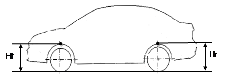
*:Coolant, engine oil, washing liquid is full. The spare tire, jack, hand tools and floor mats are all in the specified location.