Cautions for electrical technicians using medical electrics
Warning:
● There is strong magnetic components on this vehicle
● If technician use medical electrics,e.g electronic pacemakers, which couldn’t be operated in the vehicle ,otherwise,the function of electrics may be effected by strong magnetic components.
Cautions for normal charge
Warning:
● If technician use the medical electrics like pacemakers, cardiovascular, in addition to the top, the machine only could be used after the function of machine checked and confirmed before normally operation.
● In the normal charging operation, Medical electrics may be affected by electromagnetic wave. When Technicians use the medical electrics like pacemakers, cardiovascular, in addition to the top etc, it is not allowed to enter into crew capsule (including luggage).
Cautions for communication equipment
● If technicians use the medical electrics like pacemakers, cardiovascular, in addition to the top etc, please keep enough distance with the communication equipment.
● Remote intelligent terminal of electromagnetic waves may affect the function of the medical electrics like pacemakers, cardiovascular, in addition to the top etc.
● If technicians use the medical electrics like pacemakers, cardiovascular, in addition to the top etc, remote intelligent terminal of electromagnetic waves may affect the function of the medical electrics. It is needed to let the manufacturer of the medial electrics confirm that the possible affection to medical electric equipment when using remote intelligent terminal .
Keypoint checking before maintenance
High pressure system can be run automatically, it is need to confirm that remote air conditioning and recharged regularly are not set before maintenance.
Cautions:
● If set remote air-conditioner or charged regularly, even though the switch is closed, high pressure system can be run automatically.
Cautions for "safety airbag"and"safety belt preloaded"of auxiliary constraint system
The combination use of "safety airbag"and"safety belt preloaded"of auxiliary constraint system and front seat belt could decrease the damage to driver and passengers when collision. The auxiliary constraint system include seat belt, airbag for driver, airbag for co-driver. The detailed information for auxiliary constraint system could refers to the sections of “airbag system” and “seat belt”
Warning:
To avoid unexpected accident, we need to obey the following:
● To avoid the auxiliary constraint system invalid, all the maintenance only could be operated by JAC authorized distributors because the risk of injury to people will be increased after invalid.
● Non-standard auxiliary constraint system of maintenance including non-standard disassembly and installation, may result in auxiliary constraint system accident triggered, causing personal injury accidents. About remove the airbag module method, please see "airbag system" section.
● In addition to the maintenance instructions in the manual operation, do not use electrical test equipment to test any circuit of auxiliary constraint system. Auxiliary constraint system of connectors and wiring harness use yellow or orange color.
Cautions when use electrical tools (pneumatic or electric)and hammer
● when electric switch in the "ON" block, near the airbag diagnostic sensors or other sensor, do not use power tools or hammer to operate sensor parts area. Severe vibration may activate the sensor, some airbags, causing serious damage.
● When using power tools or hammer, put the keys in the "LOCK" block, unplug the 12 v lead-acid battery cathode, waiting at least 1 minute, then for checking and maintenance.
Cautions for removing 12V battery
Turn the key to “on”,then to “lock” before remove 12v battery
Tip:
● Even if the key in the "LOCK" and the 12 v battery charging function may start automatically.
● After turn the key to "ON" --> "LOCK", 12 v battery automatic charging will not start.
Cautions for rear suspension maintenance
● When installing the rubber bushing, Bolts shall be screwed under the condition of unloading and tire hit the road.
● After suspension parts maintenance, please check wheel positioning.
● There shall not be oil and grease in the installing tightening surface .
● Bumps up the vehicle with jack , don't hang the torsion bar on the jack.
Special tools
The factual tool shape may be different with the diagram showing.
|
Tool |
Diagram |
Instruction |
|
Steering transmission rod die |
|
Remove the connecting ball head |
|
Tool |
Diagram |
Instruction |
|
Power tool |
|
Install and remove bolts and nuts |
Troubleshooting for noise,vibration and unsmooth(NVH)
NVH troubleshooting diagram NVH
Using the table below helps to find the causes of symptoms. If necessary, repair or replace these parts.
|
Referring content |
Rear suspension-remove and install |
Rear suspension-shocker absober check |
-- |
-- |
-- |
Rear suspension-remove and install |
Rear suspension-wheel positioning |
Rear axle and front suspension NVH |
Wheel NVH |
Wheel NVH |
Braking system NVH |
||
|
Possible reason and parts |
Improper install, loose |
shock absorber deformed, damaged or bending |
Bushing aging |
Parts interference |
Spring fatigue |
Suspension loosing |
Not accurate for wheel positioning |
Stabilizer bar fatigue |
Rear axle and rear suspension |
Tyre |
brake |
||
|
symptom |
Rear suspention |
Noise |
√ |
√ |
√ |
√ |
√ |
√ |
|
√ |
√ |
√ |
√ |
|
|
|
Vibration |
√ |
√ |
√ |
√ |
|
√ |
|
√ |
√ |
√ |
√ |
|
|
|
Shaking |
√ |
√ |
√ |
√ |
√ |
|
|
√ |
√ |
|
|
|
|
|
fibrillation |
√ |
√ |
√ |
√ |
|
|
√ |
√ |
√ |
√ |
√ |
|
|
|
Uncomfortable or difficult to operate |
√ |
√ |
√ |
√ |
√ |
|
√ |
√ |
√ |
√ |
|
Caution:
● Check wheel positioning under unloading position.
● Front beam and camber angle can only be tested, cannot be adjusted
● If front beam and camber angle are not in the standard range, please check whether there is wearing, deformation or other damages in rear beam assembly, rear sliding column assembly and helical spring, if yes, please replace.
Basic checking
● Check whether tire pressure is normal, whether the tire has abnormal wear. Please see the "wheel - wheel assembly.
● The rear wheel hub assembly axial clearance. Please see the "rear axle - rear wheel hub assembly.
● whether each tightening parts of rear axle and suspension is loosing.
● Check whether there is crack,deformation or other damages in rear wheel hub assembly , rear sliding column and rear beam assembly.
If you find the above situation, please check after maintenance wheel alignment.
Front beam, extraversion
Place the vehicle on the four-wheel locator, see the wheel positioning data. If it is not in line with the specified value, please check after maintenance.
|
1 Rear beam assembly |
2 Rear sliding column assembly |
|
3 Rear spiral spring |
4 Rear hub assembly |
Remove
|
1 Remove the protection face of trunk 2 Remove decorative roof of rear sliding column assembly
|
|
|
3 remove two nuts of connecting rear sliding column assembly and body ● Tightening torque:30~45N·m
|
|
|
4 Remove the installing bolts of rear sliding column assembly and rear beam assembly. ● Tightening torque:60~72N·m
|
|


Warning:
● In order to ensure the maintenance staff personal safety, convenient to remove and installation, please use the geosyncline.
Caution:
● when disassembly, should avoid sliding column assembly, coil spring suddenly dropping, even cause personal injury.
Check after remove
● Check whether there is deformation, oil spills, cracks or other damage. If yes, please replace.
Install
Install in the opposite order of remove.
Caution:
● Forbid to use damaged parts.
● When install rear sliding column assembly and car body, put the two nut screw into the piston rod thread section, visual thread with 2 ~ 3 teeth (if thread to reveal too much, need to reassemble), tighten the upper nut with the torque wrench.
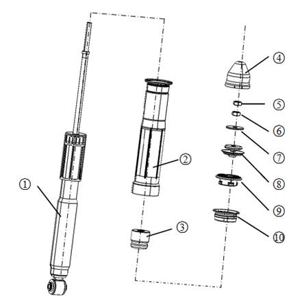
Explosion diagram
|
1 Rear shock absorber assembly |
2 Dust proof |
3 Buffer block |
4 Nut |
|
5 Nut |
6 Nut |
7.Gasket |
8 Upper rubber mat B |
|
9 Upper rubber mat A |
10 Buffer block bearing |
|
|
Caution:
● Forbid to damage rear shock absorber assembly piston rod when dissembling.
1 Remove decorative proof with flat screwdriver.
2 Remove two nuts
3 Remove the washer, rubber mat, Upper rubber mat B, Upper rubber mat A, buffer block bearing, dust cover and buffer block in order.
Check after disassembly
Rear shock absorber assembly
● Check whether there is oil leakage, deformation or other damage. If yes, please replace.
● Check if there is a scratch, deformation or other damage to the piston rod. If yes, please remove.
Buffer block, dust proof and upper rubber mat A, Upper rubber mat B
Check whether there is aging, flaw, wear or other damage. If yes, please remove.
Buffer block bearing
Check whether there is cracks, wear, deformation or other damage. If yes, please replace.
Assemble in the opposite order of disassembly
Caution:
● Forbid to use damaged parts.
● Avoid to damage piston rod when assembling.
Rear crossbeam assembly
Remove
1 Remove rear wheel hub assembly. Please see “ rear axle- rear wheel hub assembly
2 Remove braking pipe. Please see “braking system-braking pipe”
3 Remove the fixing nut for parking drawing and rear crossbeam assembly.
4 Remove the fixing bolts for rear sliding column assembly and rear crossbeam assembly.
5 Take off rear spiral spring.
Caution:
● Avoid the rear spiral spring suddenly dropping and cause personal injury when removing.
|
6 Remove the connecting bolt for rear crossbeam assembly and body. ● Tightening torque:130N·m~150N·m
|
|

● Check whether there is obvious deformation,crack, rust, liner damage or other damages for rear crossbeam. If yes, please replace.
Install
Install in the opposite order of remove.
Caution:
● Tightening tighten parts when vehicle unloaded.
● Check wheel positioning after installation.
Remove
1 Lifting the vehicle to support the rear wheel.
2 Remove the fixing bolts for rear sliding column assembly and rear crossbeam assembly.
3 Take off wheel supporting slowly and rear spiral spring,upper and down rubber mat of rear spring.
Check after remove
● Check whether there is deformation,crack, rust or other damages in rear spiral spring. If yes, please replace.
● Check whether there is cracks、aging/wearing or other damages in upper and down rubber mat of rear spring. If yes, please replace.
Install
Install in the opposite order of remove.
Caution:
● Tightening tighten parts when vehicle unloaded.
Remove
1 Lift the vehicle and remove front wheel, please see “wheel-wheel assembly”.
2 Remove rear brake clipper
3 Remove rear brake disc
4 Remove the connectting bolts of rear wheel speed sensor and rear hub assembly, remove rear wheel speed sensor.
|
5 Remove four retaining bolt of rear hub assembly and rear frame assembly, remove rear wheel hub. ● Tightening torque:60N·m~72N·m |
|
Check after remove
● Check whether there is deformation,crack or other damages in parts.
● Check whether the bub bolts is pulled long.
If there is above phenomenon, please replace.
Install
Install in the opposite order of remove
Maintenance data and specification
Wheel positioning( unloading*)
|
Camber angle |
Minimum |
-26′ |
|
standard |
-56′ |
|
|
maximum |
-1°26′ |
|
|
Left and right difference |
≤30′ |
|
|
Minimum |
0′ |
|
|
standard |
12′ |
|
|
maximum |
24′ |
Fender flares height (unloading condition *)
|
Item |
Standard value |
|
Front(Hf) |
706 |
|
Rear(Hr) |
715 |
|
|
|
*:Coolant, engine oil, washing liquid is full. The spare tire, jack, hand tools and floor mats are all in the specified location.