Cautions for electrical technicians using medical electrics
Forbidden operation
Warning:
● There is strong magnetic components on this vehicle
● If technician use medical electrics,e.g electronic pacemakers, which couldn’t be operated in the vehicle ,otherwise,the function of electrics may be effected by strong magnetic components.
Cautions for normal charge
Warning:
● If technician use the medical electrics like pacemakers, cardiovascular, in addition to the top, the machine only could be used after the function of machine checked and confirmed before normally operation.
● In the normal charging operation, Medical electrics may be affected by electromagnetic wave. When Technicians use the medical electrics like pacemakers, cardiovascular, in addition to the top etc, it is not allowed to enter into crew capsule (including luggage).
Cautions for communication equipment
● If technicians use the medical electrics like pacemakers, cardiovascular, in addition to the top etc, please keep enough distance with the communication equipment.
● Remote intelligent terminal of electromagnetic waves may affect the function of the medical electrics like pacemakers, cardiovascular, in addition to the top etc.
● If technicians use the medical electrics like pacemakers, cardiovascular, in addition to the top etc, remote intelligent terminal of electromagnetic waves may affect the function of the medical electrics. It is needed to let the manufacturer of the medial electrics confirm that the possible affection to medical electric equipment when using remote intelligent terminal .
Keypoint checking before maintenance
High pressure system can be run automatically, it is need to confirm that remote air conditioning and recharged regularly are not set before maintenance.
Cautions:
● If set remote air-conditioner or charged regularly, even though the switch is closed, high pressure system can be run automatically.
Cautions for "safety airbag"and"safety belt preloaded"of auxiliary constraint system
The combination use of "safety airbag"and"safety belt preloaded"of auxiliary constraint system and front seat belt could decrease the damage to driver and passengers when collision. The auxiliary constraint system include seat belt, airbag for driver, airbag for co-driver. The detailed information for auxiliary constraint system could refers to the sections of “airbag system” and “seat belt”
Warning:
To avoid unexpected accident, we need to obey the following:
● To avoid the auxiliary constraint system invalid, all the maintenance only could be operated by JAC authorized distributors because the risk of injury to people will be increased after invalid.
● Non-standard auxiliary constraint system of maintenance including non-standard disassembly and installation, may result in auxiliary constraint system accident triggered, causing personal injury accidents. About remove the airbag module method, please see "airbag system" section.
● In addition to the maintenance instructions in the manual operation, do not use electrical test equipment to test any circuit of auxiliary constraint system. Auxiliary constraint system of connectors and wiring harness use yellow or orange color.
Cautions when use electrical tools (pneumatic or electric)and hammer
● when electric switch in the "ON" block, near the airbag diagnostic sensors or other sensor, do not use power tools or hammer to operate sensor parts area. Severe vibration may activate the sensor, some airbags, causing serious damage.
● When using power tools or hammer, put the keys in the "LOCK" block, unplug the 12 v lead-acid battery cathode, waiting at least 1 minute, then for checking and maintenance.
Cautions for removing 12V battery
Turn the key to “on”,then to “lock” before remove 12v battery
Tip:
● Even if the key in the "LOCK" and the 12 v battery charging function may start automatically.
● After turn the key to "ON" --> "LOCK", 12 v battery automatic charging will not start.
Cautions for steering control system
● When turn steering wheel quickly,could hear the noise around steering wheel, which is the voice of the steering control system to work normally. If turn the steering wheel slowly , appear harsh noise, which is regarded as the abnormal phenomena. If yes, please repair.
Special tools
The actual tool shape may be different from illustration shown.
|
Tool |
Diagram |
Instruction |
|
Diagnostic instrument X-431 |
|
ABS system fault diagnosis |
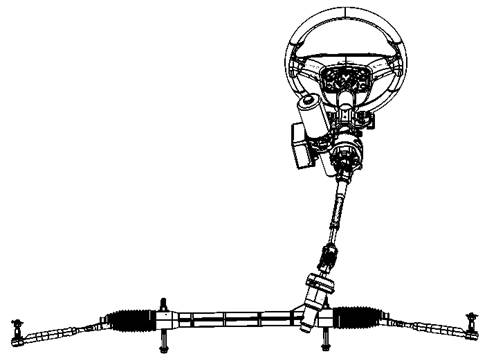
Component layout

![]()
![]()
![]()
![]()
![]()
|
1 Steering wheel assembly |
2 Steering column |
3 EPS motor |
|
4 EPS controller |
5 steering shaft with universal joint assembly |
6 Steering assembly |
System principal diagram
Description
EPS controller receives the speed signal, the electrical signal, steering torque signal, control EPS motor and provide the best power steering torque .
Electric booster steering system fault warning light
Turn the key to "START"
from the "LOCK", ,the vehicle at “READY” status, steering control
system self-check. If it is normal, the system enter the working state; If not,
electric booster steering system fault warning lights![]() lit, the system has
no power.
lit, the system has
no power.
When steering control system is
failure, electrical booster steering system fault warning light![]() lit, start
safety-invalid mode.
lit, start
safety-invalid mode.
|
Condition |
electrical
booster steering system fault warning light |
|
After “READY” |
Light off |
|
Start vehicle |
Light off |
|
Steering control system fault |
Light on |
System fault, electric booster steering system fault warning
lights![]() lit, entering into no power
or small power steering mode (steering wheel steering force will be heavier).
lit, entering into no power
or small power steering mode (steering wheel steering force will be heavier).
There is only speed signal fault, entering into small power mode, the steering force becomes obviously heavy.
Protective function
Overload using steering function (such as continuous turning in the same place), temperature of EPS controller and EPS motor rise fast, when the temperature reached set value, EPS controller control of EPS motor, reduce the working current, (overload protection).At this time, the steering force becomes obviously heavy,which is normal. Once temperature is reduced to set data, power function will recover.

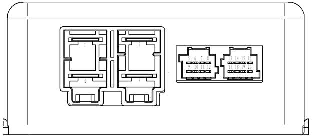
Stitch definition


|
Stitch no |
Definition |
Measuring status |
Reference |
Remark |
|
1 |
Power signal(-),ground |
|
0V |
|
|
2 |
Power signal(+) |
|
9-16V |
|
|
3 |
Motor output(-) |
No moving for steering wheel |
5-7V |
|
|
4 |
Motor output(+) |
No moving for steering wheel |
5-7V |
|
|
5 |
Sensor main angle signal(PWM-P) |
Key is in “ON”,steering wheel is in the middle |
2.5±0.05V |
|
|
6 |
Sensor vice angle signal(PWM-S) |
Key is in “ON”,steering wheel is in the middle |
2.5±0.05V |
|
|
7 |
Sensor torque pulse width signal1(PWM-T1) |
Key is in “ON”,steering wheel is in the middle |
2.5±0.05V |
|
|
8 |
Sensor torque pulse width signal 2(PWM-T2) |
Key is in “ON”,steering wheel is in the middle |
2.5±0.05V |
|
|
9 |
Power 1 (VCC1) |
Key is in “ON” |
5V |
|
|
10 |
Grounding 1(GND1) |
Key is in “ON” |
0V |
|
|
11 |
Power 2(VCC2) |
Key is in “ON” |
5V |
|
|
12 |
Grounding 2(GND2) |
Key is in “ON” |
0V |
|
|
17 |
Electrical signal |
Key is in “ON” |
12V |
|
|
19 |
CAN-L |
|
|
|
|
20 |
CAN-H |
|
|
|
Steering control system fault, fault is stored within the EPS controller, which could read through diagnosis instrument or "flash code" .
|
Serial No |
Fault code |
Description |
|
1 |
C1611 |
Main signal of torque sensor is out of range |
|
2 |
C1612 |
Vice signal of torque sensor is out of range |
|
3 |
C1613 |
Main signal and vice signal of torque sensor is out of range |
|
4 |
C1614 |
Torque sample with too long time. |
|
5 |
C1615 |
Angle abnormal fault |
|
6 |
C1317 |
Angle zero unlearning |
|
7 |
C1621 |
Battery voltage too high |
|
8 |
C1622 |
Battery voltage too low |
|
9 |
C1632 |
EEPROM data consistency fault |
|
10 |
C1641 |
Speed invalid fault |
|
11 |
C1643 |
Electrical signal loss |
|
12 |
C1651 |
Motor short circuit fault |
|
13 |
C1661 |
Relay open |
|
14 |
C1662 |
Current sensor-calibration fault of current middle |
|
15 |
C1663 |
Current sensor-over current |
|
16 |
C1664 |
+5VA voltage fault |
|
17 |
C1665 |
EPS controller- inner fault |
|
18 |
C1667 |
Temperature sensor-MOSFET overheat |
|
19 |
U1000 |
CAN-BUSOFF fault or report sending overtime |
|
20 |
U1001 |
Vehicle READY signal report overtime |
|
21 |
U1002 |
Speed signal report accepting overtime |
Diagnostic and maintenance process
Fault diagnostic process details
1 Collect customer information
Before check, carefully ask customer concerns or driving vehicles together with the customer which is very important for solving the problem.
2 Check symptom
According to the information collected through interviewing with the customer ,reappear information of customer specified symptoms. Check whether the symptoms caused by the failure mode.
Caution:
When symptoms are caused by normal operation, please fully inspect each related parts and let customers understand the symptoms are normal.
3 Check electrical booster steering system fault warning light. Please see “electrical booster steering system fault warning light check”
4 EPS fault diagnosis and maintenance
Diagnose whether there is fault code with diagnostic instrument ;
Yes>>record and delete fault code, turn to “fault code, electrical line fault diagnosis”
No>> turn to “Normal symptom and analysis”
In general, customers have their own judgment standard to a problem. Therefore, careful enough to ask to understand customer's concern is very important. Preparing interview list make diagnostic information systematic. Some times, many conditions occur at the same time resulting in failure.
Interview list sample
|
Interview list |
|||||
|
Customer name |
Gender |
Plate No |
|
Original registered date |
|
|
|
|
Model |
|
VIN |
|
|
Production date |
|
Motor power |
|
Mileage |
km |
|
Symptom |
□Steering wheel is not in the middle |
||||
|
□Electrical booster steering system fault warning light on |
|||||
|
□noise □vibration |
|||||
|
□others( ) |
|||||
|
Firstly appear |
□recently □other( ) |
||||
|
Appearing frequency |
□always □regular □sometimes( times/day) |
||||
|
Climate condition |
|
□no relation |
|||
|
|
weather |
□sunny □cloudy □rainy □snow □others( ) |
|||
|
|
temperature |
□hot □warm □Cool □Cold □temperature (about ℃) |
|||
|
|
comparative humid |
□high高 □normal □low |
|||
|
Road conditions |
□city road □suburb □highway □Mountain road □non-paving road |
||||
|
Operation conditions etc |
□no relation □Drive motor startup □Unload □Driving □Speedup □ drive with same speed □decrease speed □turning □steering wheel turning |
||||
|
Other conditions |
|
||||
|
Remark |
|
||||
Fault code、circuit fault diagnosis
Torque sensor of C1611 、C1612、C1613、C1614、C1317
|
Fault |
Item |
Instruction |
Possible reason |
|
C1611 |
Torque sensor |
Main signal of torque sensor is out of range |
Harness or connectors Torque sensor EPS controller |
|
C1612 |
Torque sensor |
Vice signal of torque sensor is out of range |
|
|
C1613 |
Torque sensor |
Main signal and vice signal of torque sensor is out of range |
|
|
C1614 |
Torque sensor |
Torque sample with too long time. |
|
|
C1615 |
Torque sensor |
Angle abnormal fault |
|
|
C1664 |
Torque sensor |
+5V power fault |
1 Preparation work
If carried out the other fault diagnosis before, please put the key in the "LOCK" block, check again after waiting for at least 10 s.
2 Check whether EPS controller pins and wiring harness connector damage or loose.
Yes>> repair or replace. Next step.
No>> Next step
3 Perform self-diagnosis
① Delete fault code
② Put the key on "LOCK" block, waiting for more than 10 s.
③ Put the key on "ON" block,
④ Check whether fault code exists.
Yes>> next step
No >> finish diagnosis
4 Replace EPS controller, check whether fault code exists.
Yes>> torque sensor fault. Please replace steering column.
No >> finish diagnosis
|
Fault |
Item |
Instruction |
Possible reason |
|
C1641 |
Speed signa |
Speed signl invalid fault |
Harness or connectors ABS EPS controller |
|
U1002 |
Speed signa |
Speed signal accepting overtime |
1 Preparation work
If carried out the other fault diagnosis before, please put the key in the "LOCK" block, check again after waiting for at least 10 s.
2 Check whether EPS controller pins and wiring harness connector damage or loose.
Yes>> repair or replace. Next step.
No>> Next step
3 Perform self-diagnosis
① Delete fault code
② Put the key on "LOCK" block, waiting for more than 10 s.
③ Put the key on "ON" block,
④ Check whether fault code exists.
Yes>> next step
No >> finish diagnosis
4 Check ABS and ground eletrical line of electric control unit
Carry out ABS diagnosis. Please see “Brake control system-fault diagnosis”to check whether there is fault.
Yes>> repair or replace.
No >> next step, finish diagnosis
5 Replace EPS controller, check whether fault code exists.
Yes>> repair or replace.
|
Fault |
Item |
Instruction |
Possible reason |
|
C1141 |
EPS motor |
Motor short circuit |
Harness or connectors EPS motor EPS controller |
1 Preparation work
If carried out the other fault diagnosis before, please put the key in the "LOCK" block, check again after waiting for at least 10 s.
2 Check whether EPS controller pins and wiring harness connector damage or loose.
Yes>> repair or replace. Next step.
No>> Next step
3 Perform self-diagnosis
① Delete fault code
② Put the key on "LOCK" block, waiting for more than 10 s.
③ Put the key on "ON" block,
④ Check whether fault code exists.
Yes>> next step
No >> finish diagnosis
4 Replace EPS controller, check whether fault code exists.
Yes>> EPS motor fault, replace steering column.
No >> finish diagnosis
EPS controller C1632、C1661、C1662、C1665、C1667
|
Fault |
Item |
Instruction |
Possible reason |
|
C1632 |
EPS controller |
EEPROM data consistency of failure |
EPS controller |
|
C1661 |
EPS controller |
Relay open |
|
|
C1662 |
EPS controller |
calibration error Of current middle point |
|
|
C1663 |
EPS controller |
Current sensor overflow |
|
|
C1665 |
EPS controller |
The control unit internal fault |
|
|
C1667 |
EPS controller |
MOSFET overheating fault |
1 Preparation work
If carried out the other fault diagnosis before, please put the key in the "LOCK" block, check again after waiting for at least 10 s.
2 Check whether EPS controller pins and wiring harness connector damage or loose.
Yes>> repair or replace. Next step.
No>> Next step
3 Perform self-diagnosis
① Delete fault code
② Put the key on "LOCK" block, waiting for more than 10 s.
③ Put the key on "ON" block,
④ Check whether fault code exists.
Yes>> next step
No >> finish diagnosis
4 Replace EPS controller
Battery voltage fault C1621、C1622
|
Fault |
Item |
Instruction |
Possible reason |
|
C1621 |
Battery voltage |
Battery voltage too high >17.5V |
Harness or connectors EPS controller fuse Power supply circuit 12V battery |
|
C1622 |
Battery voltage |
Battery voltage fault |
1 Preparation work
If carried out the other fault diagnosis before, please put the key in the "LOCK" block, check again after waiting for at least 10 s.
2 Check whether EPS controller pins and wiring harness connector damage or loose.
Yes>> repair or replace. Next step.
No>> Next step
3 Perform self-diagnosis
① Delete fault code
② Put the key on "LOCK" block, waiting for more than 10 s.
③ Put the key on "ON" block,
④ Check whether fault code exists.
Yes>> next step
No >> finish diagnosis
4 Check EPS controller grounding circuit.
① Put the key on “LOCK”block.
② Remove the EPS controller power port connector, check whether the wire end pin correspondence with the power port 1 is through with ground.
Yes >> Next step
No > > grounding circuit open circuit or short circuit. Repair or replacement, the implementation of the self-diagnosis
5 Check EPS controller power supply circuit
① Connect connectors of EPS controller at power terminal, put the key on "ON" block.
② Respectively check whether voltage between wiring harness and ground of corresponding EPS controller power port 2 and vehicle signal port 17 is normal.
Yes >> Next step
No > > harness open circuit or short circuit. Repair or replacement, the implementation of the self-diagnosis
6 Replace EPS controller.
CAN communication U1000
|
Fault |
Item |
Instruction |
Possible reason |
|
U1000 |
CAN communication |
BUS-OFF fault or CAN report sending overtime |
CAN communication EPS controller |
1 Preparation work
If carried out the other fault diagnosis before, please put the key in the "LOCK" block, check again after waiting for at least 10 s.
2 Check whether EPS controller pins and wiring harness connector damage or loose.
Yes>> repair or replace. Next step.
No>> Next step
3 Perform self-diagnosis
① Delete fault code
② Put the key on "LOCK" block, waiting for more than 10 s.
③ Put the key on "ON" block,
④ Check whether fault code exists.
Yes>> next step
No >> finish diagnosis
4 Check CAN communication system, please see “Electric tumble sub-manual - CAN communication system ", detect if there is a fault .
Yes>> repair or replace.
No>> Next step
5 Replace EPS controller,check whether fault code exists.
Yes>> repair or replace.
No>> Finish diagnosis
Steering heavily or too light
1 Carry out self-diagnosis, check whether self-diagnosis result has fault code.
Yes >>EPS fault diagnosis and maintenance.Next step.
No>> Turn to 3
2 Check symptom
Check whether there is abnormal symptom such as “heavier”or “too light”
Yes>> Next step
No >> diagnosis finish
3 Check torque sensor
Check whether the voltage between terminal 7 and 10 of torque sensor is normal.
Yes>> check and adjust steering wheel steering force. Please see”steering system- basic check”.
No>> Replace steering column.
Different steering force for left and right
1 Carry out self-diagnosis, check whether self-diagnosis result has fault code.
Yes >>EPS fault diagnosis and maintenance.Next step.
No>> Turn to 3
2 Check symptom
Check whether it is different for the steering force for left and right.
Yes>> Next step
No >> diagnosis finish
3 Front wheel alignment check
Check whether it is normal for wheel alignment. Please see “ front suspension-wheel alignment”.
Yes>> check and adjust steering wheel steering force. Please see “ check steering wheel steering force”.
No>> wheel alignment. Turn to 2.
1 Carry out self-diagnosis, check whether self-diagnosis result has fault code.
Yes >>EPS fault diagnosis and maintenance.Next step.
No>> Turn to 3
2 Check symptom
Check whether steering force vibrate.
Yes>> Next step
No >> diagnosis finish
3 Check the connection of steering shaft with universal joint is normal.
Yes>> check and adjust steering wheel steering force. Please see “ check steering wheel steering force”.
No>> Maintenance or replace. Turn to 2.