Preventive measures for electrical technicians using medical electrics
Forbidden operation
Warning:
● There is strong magnetic components on this vehicle
● If technician use medical electrics,e.g electronic pacemakers, which couldn’t be operated in the vehicle ,otherwise,the function of electrics may be effected by strong magnetic components.
Cautions for normal charge
Warning:
● If technician use the medical electrics like pacemakers, cardiovascular, in addition to the top, the machine only could be used after the function of machine checked and confirmed before normally operation.
● In the normal charging operation, Medical electrics may be affected by electromagnetic wave. When Technicians use the medical electrics like pacemakers, cardiovascular, in addition to the top etc, it is not allowed to enter into crew capsule (including luggage).
Cautions for communication equipment
● If technicians use the medical electrics like pacemakers, cardiovascular, in addition to the top etc, please keep enough distance with the communication equipment.
● Remote intelligent terminal of electromagnetic waves may affect the function of the medical electrics like pacemakers, cardiovascular, in addition to the top etc.
● If technicians use the medical electrics like pacemakers, cardiovascular, in addition to the top etc, remote intelligent terminal of electromagnetic waves may affect the function of the medical electrics. It is needed to let the manufacturer of the medial electrics confirm that the possible affection to medical electric equipment when using remote intelligent terminal .
Key points checking before maintenanc
High pressure system can be run automatically, it is need to confirm that remote air conditioning and recharged regularly are not set before maintenance.
Cautions:
● If set remote air-conditioner or charged regularly, even though the switch is closed, high pressure system can be run automatically.
Cautions for "safety airbag"and"safety belt preloaded"of auxiliary constraint system
The combination use of "safety airbag"and"safety belt preloaded"of auxiliary constraint system and front seat belt could decrease the damage to driver and passengers when collision. The auxiliary constraint system include seat belt, airbag for driver, airbag for co-driver. The detailed information for auxiliary constraint system could refers to the sections of “airbag system” and “seat belt”
Warning:
To avoid unexpected accident, we need to obey the following:
● To avoid the auxiliary constraint system invalid, all the maintenance only could be operated by JAC authorized distributors because the risk of injury to people will be increased after invalid.
● Non-standard auxiliary constraint system of maintenance including non-standard disassembly and installation, may result in auxiliary constraint system accident triggered, causing personal injury accidents. About remove the airbag module method, please see "airbag system" section.
● In addition to the maintenance instructions in the manual operation, do not use electrical test equipment to test any circuit of auxiliary constraint system. Auxiliary constraint system of connectors and wiring harness use yellow or orange color.
Cautions when use electrical tools (pneumatic or electric)and hammer
● when electric switch in the "ON" block, near the airbag diagnostic sensors or other sensor, do not use power tools or hammer to operate sensor parts area. Severe vibration may activate the sensor, some airbags, causing serious damage.
● When using power tools or hammer, put the keys in the "LOCK" block, unplug the 12 v lead-acid battery cathode, waiting at least 1 minute, then for checking and maintenance.
Turn the key to “on”,then to “lock” before remove 12v battery
Tip:
● Even if the key in the "LOCK" and the 12 v battery charging function may start automatically.
● After turn the key to "ON" --> "LOCK", 12 v battery automatic charging will not start.
Cautions for steering system maintenance
● When tightening the fixing bolt, vehicle shall be unloading and on the road, then check wheel alignment.
● Cautions for removing steering assembly
1 Please clean completely outside of steering assembly before disassembly.
2 Please dismantle in a clean working space to avoid the internal components from dust or other foreign body contamination.
3 Please put the parts on the parts rack in order after dismantling.
4 Clean components with nylon fabric or paper cloth . ordinary cloth will have residual chip cloth affecting parts operation.
5 Forbidden to reuse the components which couldn’t be used again.
6 Please grease the designated parts before assembly.
● When quick play steering wheel, could hear the noise around steering wheel, which is the voice of the steering control system to work normally. If in the process of slowly turning the steering wheel, appear harsh noise, which is the abnormal phenomena. If necessary, please repair.
● Forbid to continuous steering in the same place.
● when disassembling parts of steering system (steering column 、 EPS controller, steering shaft, steering gear), must let the steering angle of steering system be zero, otherwise, the vehicle will appear badly turn back and active partial problem.
Special tools
The actual tool shape may be different from illustration shown.
|
Tool |
Diagram |
Instruction |
|
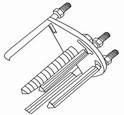
Steering wheel puller |
|
Remove steering wheel |
|
Pre-tighten measuring instrument |
|
Check the torque of the steering column assembly and the pinion assembly rotating torque |
|
Clamp pliers |
|
Remove and install dust proof clip |
|
Tool |
Diagram |
Instruction |
|
Power tool |
|
Install and remove bolts and nuts |
|
Ball joint puller |
|
Remove the outer ball head |
![]()

![]()
![]()
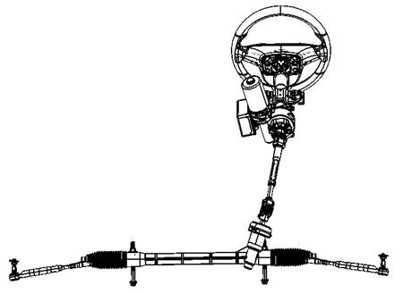
|
1 steering wheel assembly |
2 steering column assembly |
|
3 steering shaft with universal joint assembly |
4 steering assembly |
Check middle position of steering wheel
1 Confirm the correct installation position of the steering assembly, steering column assembly and the steering wheel.
2 After wheel alignment, execute the middle inspection.Please see “the front suspension - wheel position ".
3 Parking vehicles, wheels go straight on, and make sure the steering wheel in the middle position.
4 If the steering wheel is not in the middle, please loosen the tie rod rod fine-tuning lock nut and turn right or left.
Check steering force of steering wheel
1 Vehicles parked in a horizontal dry ground, the wheels straight forward and pull the parking handle.
2 Confirm the pressure of the tire value should be within the scope of the standard value. Please see the "wheel - wheel assembly"
3 Place the vehicle on “READY” status.
4 Rotate steering wheel for 360 ° from the middle position, check the steering wheel steering force, and whether steering force has obvious fluctuation.
Steering force of steering wheel:<25N allowed fluctuation:<5N
Caution:
If the steering wheel steering force is more than specified value, please check or adjust the following items:
● Whether steering rod ball head is damaged.
● Preloading of steering assembly gear and rotational torque of steering rod ball head , Please see the " steering system-steering assembly”
Check steering angle of front wheel
|
1 Check front wheel hub and detect steering angle of front wheel. 2 Place the front wheel on the steering angle measuring device (front wheel positioning steering wheel ), The vehicle is in the "READY" status, turn the steering wheel left and right to the limit position,measure the largest wheel inner and outer steering angle. |
|
|
Steering angle of inner wheel(angle A):35.1°±1.5° Steering angle of outer wheel(angle B):30.6°±1.5° |
|
|
3 If the measured value is not in the standard range, please check the following item. |
|
Steering gear stroke
Gear stroke standard value:67±0.5mm
If gear stroke surpass standard value, please replace steering assembly.
Caution:
Inner and outer wheel steering angle couldn’t be adjusted. If steering angle is different with the specified value, please check the steering gear assembly, steering column assembly and front suspension parts for wear or damage. If yes, please replace.
Learning process for steering angle of steering system to be zero
1 Put vehicles in the four-wheel positioning device to ensure qualified parameter adjustment of vehicle four-wheel positioning .
2 Adjust wheels to be straight forward and assure the steering wheel is in the middle( angle with the horizontal within0.5°)
3 Let the diagnostic instrument connect with OBD interface, the key is in the "ON" state, choose EPS calibration data in the diagnostic instrument , set the vehicle steering angle as zero, calibrate the middle position of steering wheel as zero position of steering system of EPS controller.
4 After set the steering angle as zero, please test drive and confirm, when turning back at low speed (≥10 km/h), the steering wheel can back near the middle. At the same time to ensure that the car travels in a straight line, there is no active partial problem, otherwise it is needed to check vehicle steering system again.
Troubleshooting for noise,vibration and unsmooth(NVH)
NVH troubleshooting diagramNVH
Using the table below helps to find the causes of symptoms. If necessary, repair or replace these parts.
|
Referring content |
Steering system-steering assembly check |
Steering system-steering assembly check |
Steering system-steering assembly check |
Steering system-steering wheel check |
Steering system-steering wheel check |
Steering system-steering wheel check |
Steering system-steering column assembly check |
Steering system-steering column assembly |
Steering system-steering column assembly |
Steering system-steering column assembly |
Steering system-steering shaft with universal joint assembly |
Front axle,rear axle, front suspension, rear suspension |
Wheel NVH |
Wheel NVH |
Front axle NVH |
Brake system NVH |
||
|
Possible reason and parts |
Swing torque of outer ball joint |
Swing torque of outer ball joint |
outer ball joint clearance |
steering wheel free stroke |
steering wheel steering forc |
wrong installation for steering wheel |
Tilt adjust locking lever installed incorrectly or flabby |
Fixed rubber aging |
Steering column deformation or damage |
wrong installation for Steering column or loose |
steering shaft with universal joint loose |
Front axle and suspension |
Tyre |
wheel |
Driving shaft |
Brake |
||
|
symptom |
steering |
Noise |
√ |
√ |
√ |
√ |
√ |
√ |
|
|
|
|
|
|
|
|
|
|
|
Vibration |
|
|
|
|
|
√ |
√ |
√ |
|
|
|
√ |
√ |
√ |
√ |
√ |
||
|
Shaking |
|
|
|
|
|
√ |
√ |
√ |
√ |
√ |
|
√ |
√ |
|
√ |
|
||
|
fibrillation |
|
|
|
|
|
√ |
|
√ |
|
|
√ |
√ |
√ |
√ |
|
√ |
||
|
swing |
|
|
|
|
|
|
√ |
√ |
|
|
√ |
√ |
√ |
√ |
|
√ |
||
Check
Check installing status of steering wheel
1 Confirm the installing status of steering assembly、front suspension、front axle steering column.
2 Check whether there is a gap in the steering wheel up and down, left and right sides and axial.
Steering wheel shaft end gap:0mm
3 If the shaft end clearance beyond the specified value, please check the following items:
① Check the steering column assembly condition. Please see the "steering system-steering column assembly”.
② Check if fixing bolt and nut of steering assembly loose. Please see the "steering system - steering assembly".
Check free stroke of steering wheel
1 Rotate the steering wheel to make the front wheel in the straight position.
2 Put the vehicle on “READY” status, turn slightly the steering wheel left and right to make the front wheel moving.
3 Measure the steering wheel rotating on outer circle.
Free stroke standard value of steering wheel:0~5°
4 When the measured value surpass the standard value, please check the following items:
① Check whether there is loosing in every connection point of steering column assembly.
② Check installing condition of steering assembly.
Explosion diagram

![]()
1 steering wheel
:Replace after remove ![]()
Remove
Tip:
● When connected spiral cable, cable with adhesive plaster to make the fixed part and rotational part alignment
1 Park vehicle, make the wheel straight forward.
2 Open front cover.
3 Disconnect battery cathode,and wait for more than 1 minutes.
|
4 Remove the driver airbag modules from the steering wheel. Please see the "electrical sub-manual- safety airbag system". 5 Turning the steering wheel ensures that the front wheel drive in a straight line direction. Lock steering wheel , remove the nut and ball pad of steering wheel .
|
|
Tips:
● Pull out the steering wheel and mark it to assure the reinstall position is as the same as before.
6 Pull out the steering wheel with steering wheel puller from steering axle.
Caution:
● when pulling out the steering wheel, please pre-tightening the fixing nut of the steering wheel on steering wheel to avoid hurt the maintenance people when pull out the steering wheel .
Install
Install in the opposite order of remove.
Caution:
● please don't repeat use steering wheel nut and ball pad.
● After each change or rotating spiral cable, it is necessary to check the spiral cable in the middle position, please see the "electronic systems sub-manual - combination switch".
● When installation, must make the wheels in a straight line state, at the same time, steering wheel is in the middle position. Or marking on the steering wheel and nut n advance before disassembly when installation to ensure that tag is the same.
● when the steering wheel is installed, steering column must rotate smoothly without a "click" sound.
● After the installation of steering wheel and the driver's airbag modules , loosen regulating handle of the steering column assembly and adjust the steering wheel up and down 5 ~ 6 times to check whether the steering wheel is installed well.
Check after install
● Set steering angle of steering wheel as zero, the removement of the parts of steering system will affect the steering angle , so when disassembling parts of steering system (steering column 、 EPS controller, steering shaft, steering gear), must let the steering angle of steering system be zero, otherwise, the vehicle will appear badly turn back and active partial problem.please see “ steering system-basic check”
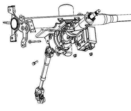
Explosion diagram
![]()

|
1Meter frame assembly |
2 Steering column assembly |
3 Steering shaft with universal joint assembly |
Remove
Caution:
● Be sure to lock the regulating handle of steering column assembly before remove the steering column assembly in order to ensure the security of personnel, convenient disassembly.
● Imposing excessive axial force on the steering column assembly is not permitted when remove.
● Mark installing tag on steering column assembly and steering shaft universal joint assembly before remove the steering shaft universal joint assembly.
● Due to the steering column assembly is heavy ,please be careful when removed from the vehicle,
● It is forbidden to close to the let steering column assembly near strong magnets.
● Steering column assembly (reduction gear, the torque sensor) cannot be disassembled
● Forbidden to rotate steering assembly and steering shaft with universal joint assembly when remove the steering column assembly.
1 Park vehicle, make the wheel straight forward.
2 Disconnect battery cathode,and wait for more than 1 minutes.
3 Adjust the steering column assembly to lowest limit location.
Caution:
● Lock adjusting handle
4 Remove downside plate assembly of driver seat,please see “ body sub-manual-dashboard”..
5 Remove the driver airbag modules,please see “electrical system sub-manual-airbag system”
6 Remove the steering wheel assembly,please see“steering system- steering wheel”
7 Remove the steering column cover (up and down), please see “body manual-dashboard”
8 Remove the spiral cable and combination switch,please see “electrical system sub-manual-combination switch”
9 Remove the ignition lock
|
10 Pull out the connectors connected with EPS controller on steering column assembly (including EPS controller power connectors and EPS controller for vehicle signal connector).
|
|
11 Remove connection bolt of the steering shaft universal joint assembly and the steering column assembly , and then remove the steering shaft with universal joint assembly from the steering column assembly.
Tightening torque:30~35N·m
Tip:
● Mark installing tag on steering shaft universal joint assembly when remove the steering shaft universal joint assembly.
Caution:
● Please do not insert the tools (such as a screwdriver) to thread groove of steering shaft universal joint assembly when remove the steering shaft universal joint assembly .Otherwise, it can damage the thread slot. If yes, please replace the steering shaft universal joint assembly.
|
12 Remove fixed nuts and bolts of steering column assembly , take off the steering column assembly.
|
|
● Tightening torque:20~30N·m
Caution:
● Avoid steering column assembly falling when remove the steering column assembly.
Check after remove
● Check the steering column assembly for cracks, deformation or other damage. If yes, please replace.
● Check the input shaft and output shaft of the steering column assembly spline for wear, broken teeth. If yes, please replace.
● Preloaded measuring instrument is used to measure the rotation torque of steering column assembly.
Standard value of rotating torque: 0~2.0N·m
If exceed standard value, please replace the steering column assembly (including motor, worm wheel mechanism, torque sensor).
|
● If vehicle has slightly hit, please measure the length of “L” L standard value:463.5±1.5mm If exceed standard value, please replace the steering column assembly (including motor, worm wheel mechanism, torque sensor). |
|
Install in the opposite order of remove.
Caution:
● Forbid to impose excessive axial force on the steering column assembly.
● Forbid to repeating use the parts which couldn’t be used again.
● Steering wheel should be in the middle when install the steering column assembly.
● When installation, check the steering column assembly and wire harness no winding, stuck
● Please pay attention to installation location when install the steering shaft universal joint assembly to the steering column assembly.
|
● Make sure connecting bolt is correctly installed in the groove(A) when connect the steering shaft universal joint assembly (1),the steering column assembly and steering gear assembly. |
|

● Please put the keys in "READY" to check whether the steering system is working properly after the installation of the steering column assembly.
Check after installation
● Check the steering wheel free stroke, middle position of steering wheel, steering wheel steering force,front wheel steering angle .
Steering wheel free stroke, please see”steering system-steering wheel”
Middle position of steering wheel, steering wheel steering force,front wheel steering angle , please see” steering system-basic check”.
● Loose the regulating handle of steering column assembly to check whether adjusting steering column assembly up and down is smoothly.
● Set steering angle of steering wheel as zero, the removement of the parts of steering system will affect the steering angle , so when disassembling parts of steering system (steering column 、 EPS controller, steering shaft, steering gear), must let the steering angle of steering system be zero, otherwise, the vehicle will appear badly turn back and active partial problem.please see “ steering system-basic check”
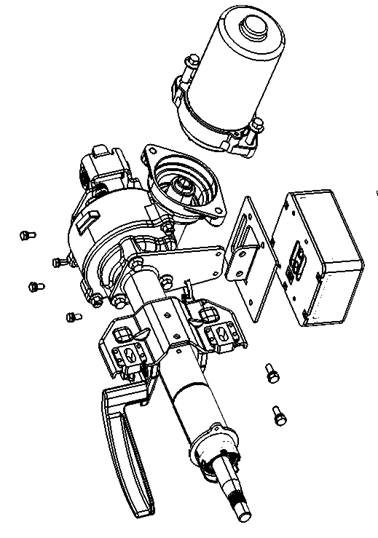
Explosion diagram
|
1 EPS motor EPS |
2 EPS controller |
3 Controller fixing bracket |
4 Steering column |
1 Plug out EPS controller connectors
|
2 Remove the fixing bolt of controller fixing bracket and steering column,take off controller fixing bracket. |
|
Caution:
Fix steering column with the hands or tools when loose the nut.
3 Remove the EPS controller fixing bolt, take off the EPS controller.
Tightening torque: 10~15N•m
4 Remove the fixing bolt of EPS motor and steering column, take off EPS motor.
Caution:
● Forbid to result in knock and other damage to EPS motor when removing motor, Removing EPS motor. If yes, please replace.
Check after disassembly
EPS controller
Check whether there is any crack, loose ,curved needle or other malfunctionon EPS controller connectors . If yes, please replace.
EPS motor
Check whether there is any knock against, grinding marks or other malfunction on surface of EPS motor. If yes, please replace.
Steering column
Check whether there is any crack, deformation, corrosion, or other failure on the surface of the steering column. If yes, please replace.
Install
Install in the opposite order of remove
Caution:
● Forbid to apply too much axial force to the steering column.
● Forbid to repeating use the parts which couldn’t be used again.
Steering shaft with universal joint assembly
Explosion diagram

Remove
Caution:
● Turning the steering wheel is prohibited to avoid spiral cable twist off when separating steering column assembly and steering shaft with universal joint assembly.
1 Parking vehicles with wheels going straight forward.
2 Adjust the regulating handle of the steering column assembly to the lowest limit position.
Caution:
● Lock adjusting handle
3 Remove downside guard plate assembly of the driver seat.
4 Remove the fixing bolt of steering shaft with universal joint and steering assembly, separating steering shaft with universal joint assembly and steering assembly.
● Tightening torque:30~35N·m
Tips:
● Mark installing tag on steering assembly and steering shaft with universal joint assembly when remove the steering shaft universal joint assembly.
Caution:
● Please do not insert the tools (such as a screwdriver) to thread groove of steering shaft universal joint assembly when remove the steering shaft universal joint assembly .Otherwise, it can damage the thread slot. If yes, please replace the steering shaft universal joint assembly.
|
5 Remove the fixing bolt of steering shaft with universal joint and steering assembly, take off steering shaft with universal joint assembly |
|
● Tightening torque:30~35N·m
Tips:
● Mark installing tag on steering column assembly and steering shaft with universal joint assembly when remove the steering shaft universal joint assembly.
Check after remove
Check the steering shaft universal joint assembly of components for crack, rust or other damage. If yes, please replace.
Install
Install in the opposite order of remove, pre-tightening by hand ,then tightening with tools when tightening bolts.
|
Tips: ● Make sure connecting bolt is correctly installed in the groove(A) when connect the steering shaft universal joint assembly (1),the steering column assembly and steering gear assembly. |
|
Check after installation
1 Put the vehicle on “READY”status and turn the steering wheel to check whether there is abnormal noise , shaking or steering force vibration. If yes, please replace steering shaft with universal joint assembly.
● Check the steering wheel free stroke, middle position of steering wheel, steering wheel steering force,front wheel steering angle .
Steering wheel free stroke, please see”steering system-steering wheel”
Middle position of steering wheel, steering wheel steering force,front wheel steering angle , please see” steering system-basic check”.
● Set steering angle of steering wheel as zero, the removement of the parts of steering system will affect the steering angle , so when disassembling parts of steering system (steering column 、 EPS controller, steering shaft, steering gear), must let the steering angle of steering system be zero, otherwise, the vehicle will appear badly turn back and active partial problem.please see “ steering system-basic check”
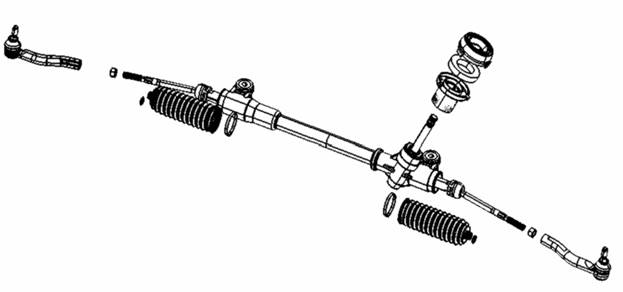
Explosion diagram

|
1 Split pin |
2 Nut |
3 Steering assembly |
4 Front vice frame |
:Replace
after remove ![]()
Remove
1 Parking vehicles with wheels going straight forward.
|
2 Remove the fixing bolt of steering shaft with universal joint and steering assembly,separating steering shaft with universal joint assembly. |
|
Tips:
● Mark installing tag on steering assembly and steering shaft with universal joint assembly when remove the steering shaft universal joint assembly.
Caution:
● Please do not insert the tools (such as a screwdriver) to thread groove of steering shaft universal joint assembly when remove the steering shaft universal joint assembly .Otherwise, it can damage the thread slot. If yes, please replace the steering shaft universal joint assembly.
● Forbid to turning steering wheel to avoid cut the spiral cable when separating steering shaft with universal joint and steering assembly.
3 Lifting vehicle
4 Remove front wheel
|
5 Remove steering tie rod ① Remove split pin of steering tie rod. ② Loose the fixing nut on the tie rod ● Tightening torque:40~50N·m
|
|
|
③ Remove the steering tie rod with ball joint puller (or appropriate tools) from the steering knuckle so as not to damage the ball head dust cover.
|
|
Caution:
● Temporarily tighten nut can prevent damage to thread section and suddenly dropping of ball puller.
6 Remove vice frame. Please see “front suspension-front vice frame”
|
7 Remove fixing bolt and nut of steering assembly on front vice frame, take off steering assembly. Tightening torque:95~105N·m Caution: Damage the steering rack dustproof cover is prohibited. |
|
Install in the opposite order of remove.
|
Caution: ● Clean steering proof① and front board② sealing surface when installing steering assembly.
|
|

● Make steering gear cover and body closely when installing steering assembly .
● Forbid to turning steering wheel to avoid cut the spiral cable when steering shaft with universal joint connecting with steering assembly.
● Tighten the ball head nut of tie rod when vehicle unloading and tire on the road.
Check after install
1 Turn the steering wheel to the limit position for several times, Whether steering wheel operation is smooth and flexible during the whole process of steering.
2 Check the steering wheel free stroke, middle position of steering wheel, steering wheel steering force,front wheel steering angle .
Steering wheel free stroke, please see”steering system-steering wheel”
Middle position of steering wheel, steering wheel steering force,front wheel steering angle , please see” steering system-basic check”.
● Set steering angle of steering wheel as zero, the removement of the parts of steering system will affect the steering angle , so when disassembling parts of steering system (steering column 、 EPS controller, steering shaft, steering gear), must let the steering angle of steering system be zero, otherwise, the vehicle will appear badly turn back and active partial problem.please see “ steering system-basic check”
Caution:
● Turn the steering wheel to check whether there is abnormal noise and steering force is too large
● After the installation is complete, please adjust the tie rod length from left to right according to former set bunch of value , after the completion of the adjustment, tightening with the lock nut and check wheel alignment. Please see “front suspension-wheel alignment”
● After wheel positioning, the steering angle of steering wheel could be set as zero.
Explosion diagram
|
1 Steering tie rod |
2 Nut |
3 Inner tie |
4 Rack sleeve |
5 Steering cover |
|
6 Shield damping ring |
7 Shield seat |
8 Steel band elastic hoop |
9 Rack dust proof |
10 Rack dust cover band |
1 Remove the steering gear cover, shield damping ring and shield seat.
2 Loosen the tie rod nut, rotate steering tie rod, till the inner tie out and take off the nut.
● Tightening torque:45~55N•m
Caution:
When Loosing the nut, fixing steering tie rod with wrench or other tools.
3 Remove steel band elastic clamp on gear dust proof and gear dust cover clip, take off the rack dust cover.
Caution:
● Forbid to damage inner tie rod and the rack casing when take off the rack dust cover. If damaged, please replace.
Check after dissasembly
Rack dust cover
Check whether there is any crack, breakage on rack dust cover. If yes, please replace.
Rack casing
Check whether there is crack, wear, corrosion, or other malfunction in the rack casing. If yes, please replace.
|
Steering tie rod and inner tie Swing torque of ball joint: hook the parts as shown in the diagram and pull the spring balance. When the ball stud and inner ball joint start moving, reading the spring balance values. If beyond the standard, please replace. |
|
|
Item |
Outer ball joint |
Inner ball joint |
|
Measuring point of spring balance |
Upper of ball stud |
Remark ☆in the measuring diagram |
|
Swing torque |
0.5~3.0N•m |
0.5~3.0N•m |
|
Spring balance measure |
3.3~20N |
9.3~55.5N |
Axial clearance of ball joint
|
Pressure the ball screw with 490 N axial force. Measure stud moving value, and then confirm the value in the range of the following provisions. If the tested value exceeds the standard, please replace the tie rod ① and inner tie rod ②. Inner ball joint:≤0.15mm Outer ball joint:≤0.15mm |
|
1 Install cover seat, shield damping ring and the steering cover on steering.
2 Grease on the inner tie rod.
Grease type:SHELL NERITA
Greasing quantity:3~5g
3 Grease installation location of inner tie rod steel band elastic hoop along with the groove direction, install rack dust cover.
Grease type: GREAT WALL 7501 High vacuum silicon grease
Greasing quantity: 2g
Caution:
● Forbid to repeat to use the rack dust cover.
|
4 Install rack dust cover clip①on rack dust cover Tighten with Clamp pliers.
|
|
Caution:
● Forbid to repeat to use rack dust cover clip.
● As shown in the diagram, please install rack dust cover clamp in the groove of dust cover clamp, tighten clamp till the gap less than 3 mm.
|
5 Install steel band spring clip(small)on rack dust cover.
|
|
Caution:
● Forbid to reuse steel band elastic hoop.
6 Install nut① and steering tie rod.
|
7 Adjust standard length “L”of inner tie, then tighten nut① to specified torque.After tightening, check the inner tie length “L”again.Standard value of L:80±1mm.
|
|
Caution:
● Need wrench to fix steering tie rod② when tightening nut①.
Maintenance data and specification
Steering wheel clearance and stroke
|
Item |
Standard |
|
Steering wheel clearance |
0 |
|
Steering wheel free stroke |
5 |
|
Item |
Standard |
|
Steering wheel steering force |
≤25 |
|
Item |
Standard |
|
Max inner wheel angle |
35.1±1.5 |
|
Max outer wheel angle |
30.6±1.5 |
|
Item |
Standard |
|
Angle adjusting range |
3.3±1 |
|
Rotating torque |
0~2.0 |
|
Steering column length |
463.5±1.5 |
|
Item |
Standard |
|
Rack middle place |
67±0.5 |
|
Item |
Standard |
|
Outer ball joint |
0.5~3.0 |
|
Inner ball joint |
0.5~3.0 |
|
Item |
Standard |
|
Outer ball joint |
≤0.15 |
|
Inner ball joint |
≤0.15 |
|
Item |
Standard |
|
Rack middle place |
80±1 |